2005 MERCEDES-BENZ SPRINTER oil reset
[x] Cancel search: oil resetPage 18 of 1232
MAINTENANCE - WITH ASSYST MAINTENANCE
COMPUTER
ASSYST provides information on the best possible
timing for maintenance work.
NOTE: The engine manufacturer strongly recom-
mends the use of synthetic engine oils, such as
TMobil 1 SAE 0W-40.
When the next maintenance service is due, this
will be indicated in the multi-function display with
the wrench icon symbol displayed in km/miles or
days.
²One wrench icon showing indicates Oil Service
is necessary.
²Two wrench icons showing indicates Mainte-
nance Service is necessary ± displayed in km/miles or
days.
If the display shows the number of days, a clock
symbol will also appear in the multi-function display.
You should have the maintenance performed
within the stated period/distance.
The service indicator should be reset after an oil
service and/or maintenance service has been per-
formed.
REGULAR CHECK-UPS
To maintain the safe operation of the vehicle, it is
recommended that the following tasks be performed
on a regular basis (i.e. weekly or whenever the vehi-
cle is refueled). Check:
²Engine oil level
²Brake system, clutch mechanism ± fluid level
²Battery ± acid level
²Windshield washer system and headlamp clean-
ing system ± fluid level
²Mechanical assemblies (e. g. engine, transmis-
sion, etc.) ± check for leaks
²Condition of tires and tires pressures
²All exterior lights
SPECIAL MAINTENANCE REQUIREMENTS
If bodies built by manufacturers other than
DaimlerChrysler Corporation are fitted to the vehi-
cle, the maintenance requirements and lubrication
intervals specified by the body manufacturer must be
adhered to, in addition to all standard maintenance
requirements.
Brake Fluid
Only use brake fluids approved by the manufac-
turer (DOT 4 plus).
Coolant
Corrosion inhibitor/antifreeze concentration in the
coolant should be checked before the onset of winter
(once year in countries with high prevailing temper-
atures).Replace the coolant every five years or 100,000
miles.
Dust Filter for Heating/Ventilation Replace-
ment
The dust filter and the tailgate interior filter are to
be renewed during routine maintenance service. If
operating conditions are dusty, these filters should be
renewed more frequently.
ENGINE OIL CHANGE AND FILTER REPLACEMENT
At the minimum, change the engine oil and oil fil-
ter once a year ± even if the vehicle mileage per year
is extremely low. For standard oil service schedules
refer to the chapter oil service and maintenance ser-
vice.
Once a Year
Select the viscosity of the engine oil (SAE classes)
according to the outside air temperature.
Only use engine oil approved by DaimlerChrysler
Corporation if following the ASSYST system guide-
lines.
If the fuel used has a sulphur content exceeding
0.05% by weight, the service intervals should be split
in half.
SCOPE OF WORK FOR MAINTENANCE SERVICE
Oil Service
²Engine:
Oil change and filter replacement
Check fluid levels of the following system,
refill as necessary.
²If fluid is lost, trace and eliminate cause ± as a
separate order.
²Power-assisted steering
Lubrication work:
²Trailer tow hitch (original equipment)
Maintenance
²ASSYST maintenance computer reset
Function check
²Signalling system, warning and indicator lamps
²Headlamps, exterior lighting
²Windshield wipers, windshield washer system
Check for leaks and damage.
²Check for abrasion points and ensure that lines
are correctly routed!
²All lines and hoses, sensor cables
²Rubber boots on front axle drive shafts, rubber
boots on front axle suspension ball joints, shock
absorbers
Check fluid levels for the following systems,
correct as necessary.
NOTE: Should there be a loss of fluid which cannot
be explained by regular use, trace and eliminate the
cause.
0 - 8 LUBRICATION & MAINTENANCEVA
MAINTENANCE SCHEDULES (Continued)
Page 189 of 1232
ule (ECM) over the Controller Area Network (CAN)
data bus. The low oil level indicator Light Emitting
Diode (LED) is completely controlled by the instru-
ment cluster logic circuit, and that logic will only
allow this indicator to operate when the instrument
cluster detects that the ignition switch is in the On
position. Therefore, the LED will always be off when
the ignition switch is in any position except On. The
LED only illuminates when it is provided a path to
ground by the instrument cluster transistor. The
instrument cluster will turn on the low oil level indi-
cator for the following reasons:
²Bulb Test- Each time the ignition switch is
turned to the On position the low oil level indicator
is illuminated for about two seconds as a bulb test.
²Engine Oil Level Low Message- Once the
engine has been started, each time the cluster
receives a message from the ECM indicating that the
engine oil level is at or near the ªMinimumº mark on
the dipstick, the low oil level indicator is illuminated.
The indicator remains illuminated briefly at first, but
will remain illuminated for longer periods as subse-
quent messages indicate that the oil level has
dropped further. Eventually, the indicator will
remain illuminated solid until the engine oil level is
corrected, or until the ignition switch is turned to the
Off position, whichever occurs first.
The instrument cluster also supplements the oil level
indicator by displaying an engine oil icon along with
alpha-numeric messages in the multi-function indicator
Liquid Crystal Display (LCD) advising the vehicle oper-
ator how much oil is required to correct the engine oil
level, and when the ªMaximumº engine oil level has
been exceeded. See the owner's manual in the vehicle
glove box for more information on this feature.
The ECM continually monitors the engine oil level
and temperature sensor to determine the engine oil
level. The ECM then sends the proper engine oil
level messages to the instrument cluster. If the
instrument cluster turns on the indicator after the
bulb test, even after the engine oil level is sufficient,
it may indicate that the engine or the engine oiling
system requires service. For proper diagnosis of the
engine oil level and temperature sensor, the ECM,
the CAN data bus, or the electronic message inputs
to the instrument cluster that control the low oil
level indicator, a DRBIIItscan tool is required. Refer
to the appropriate diagnostic information.
MAINTENANCE INDICATOR
DESCRIPTION
An Active Service SYSTem (ASSYST) engine oil main-
tenance indicator is optional equipment on all instru-
ment clusters. In vehicles so equipped, a second,dedicated ASSYST microprocessor is integral to the
cluster electronic circuit board. The ASSYST indications
are displayed and can be toggled with the clock indica-
tion on the right side of the multi-function indicator
Liquid Crystal Display (LCD) located near the lower
edge of the instrument cluster, directly below the speed-
ometer. The ASSYST displays include numeric values
combined with several icons to indicate actual engine oil
level, and reminders in time (days) or distance (miles or
kilometers) until the next required engine oil mainte-
nance is anticipated. ASSYST also provides several
audible indications using the electronic tone generator
on the instrument cluster circuit board to supplement
these visual displays.
The indications of the ASSYST engine oil mainte-
nance indicator are not visible when the LCD is not illu-
minated. When illuminated, the ASSYST indications
appear as dark characters and icons silhouetted against
an amber field. When the exterior lighting is turned Off,
the display is illuminated at maximum brightness.
When the exterior lighting is turned On, the display
illumination level can be adjusted in concert with the
cluster general illumination lighting using the ª+º (plus)
and ª2º (minus) multi-function indicator push buttons.
The ASSYST engine oil maintenance indicator is ser-
viced as a unit with the instrument cluster.
OPERATION
The ASSYST engine oil maintenance indicator micro-
processor uses numerous criteria besides time and mile-
age to evaluate vehicle maintenance requirements. Time
data is taken from the electronic digital clock integral to
the instrument cluster. Vehicle distance data is obtained
from the Controller Antilock Brake (CAB) over the Con-
troller Area Network (CAN) data bus. Coolant tempera-
ture, engine oil temperature, engine oil level, engine oil
quality, engine speed, and engine load data are obtained
from the Engine Control Module (ECM) over the CAN
data bus. Using all of the available data and internal
programming, the ASSYST microprocessor then calcu-
lates the estimated time and distance to the next
required engine oil maintenance interval. The ASSYST
uses the multi-function indicator LCD to display that
data and, when necessary, issues audible alerts to the
vehicle operator through the electronic tone generator
on the cluster circuit board.
See the owner's manual in the vehicle glove box for
more information on the features, use, operation and
resetting procedures for the ASSYST maintenance
computer. Proper diagnosis and testing of the
ASSYST engine oil maintenance computer, the CAN
data bus and the electronic data bus message inputs
to the EMIC that are used by the ASSYST computer
for its calculations requires the use of a DRBIIIt
scan tool. Refer to the appropriate diagnostic infor-
mation.
VAINSTRUMENT CLUSTER 8J - 19
LOW OIL LEVEL INDICATOR (Continued)
Page 734 of 1232
OPERATION
The cigar lighter consists of two major components:
a knob and heating element unit, and the cigar
lighter base or receptacle shell. The receptacle shell
is connected to ground, and an insulated contact in
the bottom of the shell is connected to battery cur-
rent. The cigar lighter receives battery voltage from a
fuse in the fuseblock only when the ignition switch is
in the Accessory or On positions.
The knob and heating element are encased within
a spring-loaded housing, which also features a sliding
protective heat shield. When the heating element is
inserted in the receptacle shell, the heating element
resistor coil is grounded through its housing to the
receptacle shell. If the cigar lighter knob is pushed
inward, the heat shield slides up toward the knob
exposing the heating element.
Two small spring-clip retainers are located on
either side of the insulated contact inside the bottom
of the receptacle shell. These clips engage and hold
the heating element against the insulated contact
long enough for the resistor coil to heat up and glow.
When the resistor coil becomes sufficiently heated,
excess heat radiates from the heating element caus-
ing the spring-clips to expand. Once the spring-clips
expand far enough to release the heating element,
the spring-loaded housing forces the knob and heat-
ing element to pop back outward to their relaxed
position. When the cigar lighter knob and element
are pulled out of the receptacle shell, the protective
heat shield slides downward on the housing so that
the heating element is recessed and shielded around
its circumference for safety.
DIAGNOSIS AND TESTING - CIGAR LIGHTER
OUTLET
For cigar lighter outlet diagnosis and testing pro-
cedures (Refer to 8 - ELECTRICAL/POWER DISTRI-
BUTION/POWER OUTLET - DIAGNOSIS AND
TESTING)
REMOVAL
For cigar lighter outlet removal procedure (Refer to
8 - ELECTRICAL/POWER DISTRIBUTION/POWER
OUTLET - REMOVAL).
CIRCUIT BREAKER
DESCRIPTION
Automatic resetting circuit breakers are used to
protect the power window voltage supply circuits.
These circuit breakers can protect the systems from a
short circuit, or from an overload condition caused by
an obstructed or stuck power window regulator or
switch.The circuit breaker cannot be repaired and, if
faulty or damaged, it must be replaced.
OPERATION
The circuit breaker contains a bi-metal strip sand-
wiched between two contacts forming the connection
in the circuit. An overload condition causes the
bi-metal strip to heat and bend to the open position,
disconnecting current flow to the circuit. Then as the
system overload or short circuit is removed, the
bi-metal strip cools, re-establishing contact to allow
current flow to the circuit.
DIAGNOSIS AND TESTING - CIRCUIT BREAKER
For complete circuit descriptions and diagrams,
refer toWiring.
(1) Locate the correct circuit breaker in the fuse-
block. Pull out the circuit breaker slightly, but be cer-
tain that the circuit breaker terminals still contact
the terminals in the fuseblock cavities.
(2) Connect the negative lead of a 12-volt DC volt-
meter to a good ground.
(3) With the voltmeter positive lead, check both
terminals of the circuit breaker for battery voltage.
If only one terminal has battery voltage, the circuit
breaker is faulty and must be replaced. If neither ter-
minal has battery voltage, repair the open circuit
from the Power Distribution Center as required.
FUSE BLOCK #1
DESCRIPTION
An electrical fuse block is concealed under the
driver side steering column. The fuse block serves to
distribute electrical current to many of the electrical
systems in the vehicle. The fuse block contains blade-
type mini fuses, relays and micro processors that
enable automatic control of some of the power distri-
bution circuits throughout the vehicle.
The molded plastic fuse block housing has an inte-
gral mounting bracket that is secured with screws to
the steering column. A finger recess is molded into
the cover for easy removal. A fuse layout map is
molded onto the back side of the cover to ensure
proper fuse identification.
The fuse block cannot be repaired, if the fuse block
is faulty or damaged or if any internal circuit is
faulty or damaged, the entire fuse block must be
replaced.
OPERATION
All of the circuits entering and leaving the fuse
block do so through the instrument panel wire har-
ness. Internal connection of all of the fuse block cir-
cuits is accomplished by an intricate combination of
8W - 97 - 2 8W-97 POWER DISTRIBUTIONVA
CIGAR LIGHTER OUTLET (Continued)
Page 792 of 1232
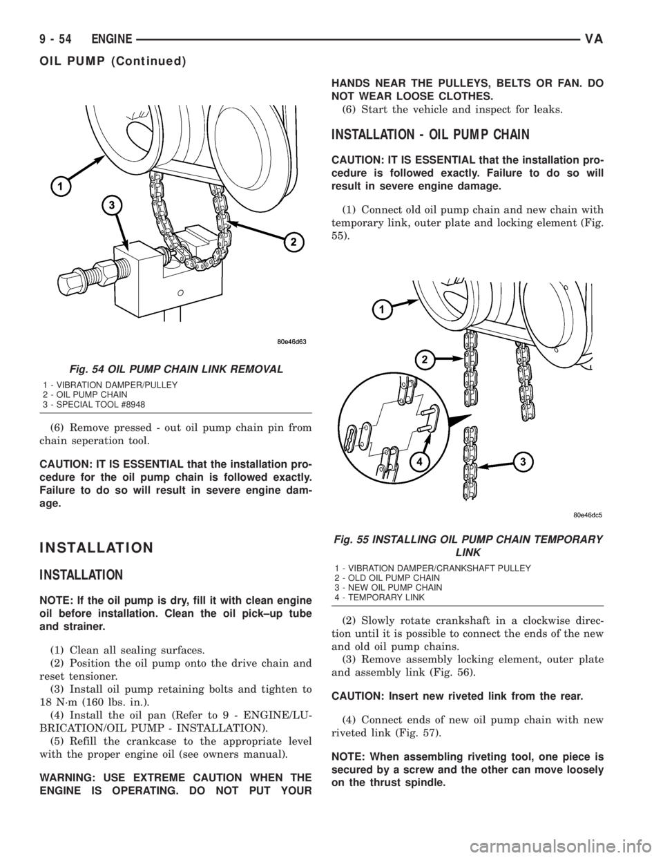
(6) Remove pressed - out oil pump chain pin from
chain seperation tool.
CAUTION: IT IS ESSENTIAL that the installation pro-
cedure for the oil pump chain is followed exactly.
Failure to do so will result in severe engine dam-
age.
INSTALLATION
INSTALLATION
NOTE: If the oil pump is dry, fill it with clean engine
oil before installation. Clean the oil pick±up tube
and strainer.
(1) Clean all sealing surfaces.
(2) Position the oil pump onto the drive chain and
reset tensioner.
(3) Install oil pump retaining bolts and tighten to
18 N´m (160 lbs. in.).
(4) Install the oil pan (Refer to 9 - ENGINE/LU-
BRICATION/OIL PUMP - INSTALLATION).
(5) Refill the crankcase to the appropriate level
with the proper engine oil (see owners manual).
WARNING: USE EXTREME CAUTION WHEN THE
ENGINE IS OPERATING. DO NOT PUT YOURHANDS NEAR THE PULLEYS, BELTS OR FAN. DO
NOT WEAR LOOSE CLOTHES.
(6) Start the vehicle and inspect for leaks.
INSTALLATION - OIL PUMP CHAIN
CAUTION: IT IS ESSENTIAL that the installation pro-
cedure is followed exactly. Failure to do so will
result in severe engine damage.
(1) Connect old oil pump chain and new chain with
temporary link, outer plate and locking element (Fig.
55).
(2) Slowly rotate crankshaft in a clockwise direc-
tion until it is possible to connect the ends of the new
and old oil pump chains.
(3) Remove assembly locking element, outer plate
and assembly link (Fig. 56).
CAUTION: Insert new riveted link from the rear.
(4) Connect ends of new oil pump chain with new
riveted link (Fig. 57).
NOTE: When assembling riveting tool, one piece is
secured by a screw and the other can move loosely
on the thrust spindle.
Fig. 54 OIL PUMP CHAIN LINK REMOVAL
1 - VIBRATION DAMPER/PULLEY
2 - OIL PUMP CHAIN
3 - SPECIAL TOOL #8948
Fig. 55 INSTALLING OIL PUMP CHAIN TEMPORARY
LINK
1 - VIBRATION DAMPER/CRANKSHAFT PULLEY
2 - OLD OIL PUMP CHAIN
3 - NEW OIL PUMP CHAIN
4 - TEMPORARY LINK
9 - 54 ENGINEVA
OIL PUMP (Continued)
Page 804 of 1232
CAUTION: IT IS ESSENTIAL that the installation pro-
cedure for the timing chain is followed exactly. Fail-
ure to do so will result in severe engine damage.
INSTALLATION
INSTALLATION - TENSIONING AND SLIDE RAIL
NOTE: Carefully clean all mating surfaces with
appropriate solvents to assure that no grease or oil
is present during reassembly.
CAUTION: ENSURE THAT THE SPRING IS COR-
RECTLY INSTALLED ON THE TENSIONING CLAMP
AND SLIDE RAIL.
(1) Install rail on bearing pin (Fig. 67).
(2) Install timing cover (Refer to 9 - ENGINE/
VALVE TIMING/TIMING BELT / CHAIN COVER(S)
- INSTALLATION).
(3) Install oil pan bolts. Tighten M6 bolts to 9N´m
(80 lbs.in.) and M8 bolts to 20N´m (15 lbs. ft.).
(4) Install cylinder head (Refer to 9 - ENGINE/
CYLINDER HEAD - INSTALLATION).
(5) Install the engine.
(6) Reconnect negative battery cable.
WARNING: USE EXTREME CAUTION WHEN THE
ENGINE IS OPERATING. DO NOT STAND IN A
DIRECT LINE WITH THE FAN. DO NOT PUT YOUR
HANDS NEAR THE PULLEYS, BELTS OR FAN. DO
NOT WEAR LOOSE CLOTHES.
(7) Start the engine and inspect for leaks. care
must be take to observe the fuel system warning
(Refer to 14 - FUEL SYSTEM - WARNING).
INSTALLATION - INTERMEDIATE GEAR
NOTE: Refer to appropriate injector servicing proce-
dures for cleaning of injectors and recesses.
(1) Install intermediate gear and bushing. Tighten
bolt to 40N´m (30 lbs.ft.)
(2) Install camshaft sprocket, noting dowel pin
alignment. Tighten bolt to 18 N´m (159 lbs. in.).
(3) Remove tie strap retaining timing chain to
sprocket.
WARNING: NO FIRE, FLAMES OR SMOKING. SER-
VICE VEHICLE IN WELL VENTILATED AREA. RISK
OF INJURY FROM INHALING OR SWALLOWING
FUEL. RISK OF INJURY TO EYES AND SKIN FROM
CONTACT WITH FUEL. WEAR PROTECTIVE CLOTH-
ING.(4) Install high pressure pump (Refer to 14 -
FUEL SYSTEM/FUEL DELIVERY/FUEL INJEC-
TION PUMP - INSTALLATION).
(5) Install top slide rail (Refer to 9 - ENGINE/
VALVE TIMING/TIMING BELT/CHAIN AND
SPROCKETS - INSTALLATION).
(6) Install cylinder head front cover (Refer to 9 -
ENGINE/CYLINDER HEAD - INSTALLATION).
(7) Install timing chain tensioner with new gasket
(Refer to 9 - ENGINE/VALVE TIMING/TIMING
BELT/CHAIN AND SPROCKETS - INSTALLA-
TION).
NOTE: Inspect basic position of camshaft and reset
if necessary.
(8) Remove camshaft locking pin.
(9) Install cylinder head cover (Refer to 9 -
ENGINE/CYLINDER HEAD/CYLINDER HEAD
COVER(S) - INSTALLATION).
WARNING: NO FIRE, FLAMES OR SMOKING. SER-
VICE VEHICLE IN WELL VENTILATED AREA. RISK
OF INJURY FROM INHALING OR SWALLOWING
FUEL. RISK OF INJURY TO EYES AND SKIN FROM
CONTACT WITH FUEL. WEAR PROTECTIVE CLOTH-
ING.
(10) Install fuel high pressure lines and injectors
(Refer to 14 - FUEL SYSTEM/FUEL INJECTION/
FUEL INJECTOR - INSTALLATION).
(11) Install engine cover (Refer to 9 - ENGINE -
INSTALLATION).
(12) Connect negative battery cable.
WARNING: USE EXTREME CAUTION WHEN THE
ENGINE IS OPERATING. DO NOT STAND IN A
DIRECT LINE WITH FAN. DO NOT PUT YOUR
HANDS NEAR THE PULLEYS, BELTS OR FAN. DO
NOT WEAR LOOSE CLOTHING.
(13) Start engine and inspect for leaks. Care must
be taken to observe the fuel system warning (Refer to
14 - FUEL SYSTEM - WARNING).
INSTALLATION - TIMING CHAIN TENSIONING
RAIL
NOTE: Carefully clean all mating surfaces with
appropriate solvents to assure that no grease or oil
is present during reassembly.
(1) Install tensioning rail on bearing pin
(2) Install timing cover (Refer to 9 - ENGINE/
VALVE TIMING/TIMING BELT / CHAIN COVER(S)
- INSTALLATION).
9 - 66 ENGINEVA
TIMING BELT/CHAIN AND SPROCKETS (Continued)
Page 867 of 1232
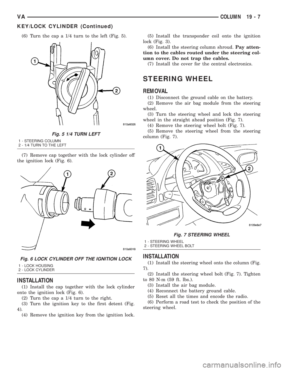
(6) Turn the cap a 1/4 turn to the left (Fig. 5).
(7) Remove cap together with the lock cylinder off
the ignition lock (Fig. 6).
INSTALLATION
(1) Install the cap together with the lock cylinder
onto the ignition lock (Fig. 6).
(2) Turn the cap a 1/4 turn to the right.
(3) Turn the ignition key to the first detent (Fig.
4).
(4) Remove the ignition key from the ignition lock.(5) Install the transponder coil onto the ignition
lock (Fig. 3).
(6) Install the steering column shroud.Pay atten-
tion to the cables routed under the steering col-
umn cover. Do not trap the cables.
(7) Install the cover for the central electronics.
STEERING WHEEL
REMOVAL
(1) Disconnect the ground cable on the battery.
(2) Remove the air bag module from the steering
wheel.
(3) Turn the steering wheel and lock the steering
wheel in the straight ahead position (Fig. 7).
(4) Remove the steering wheel bolt (Fig. 7).
(5) Remove the steering wheel from the steering
column (Fig. 7).
INSTALLATION
(1) Install the steering wheel onto the column (Fig.
7).
(2) Install the steering wheel bolt (Fig. 7). Tighten
to 80 N´m (59 ft. lbs.).
(3) Install the air bag module.
(4) Reconnect the battery ground cable.
(5) Reset all the times and encode the radio.
(6) Perform a road test to check the position of the
steering wheel.
Fig. 5 1/4 TURN LEFT
1 - STEERING COLUMN
2 - 1/4 TURN TO THE LEFT
Fig. 6 LOCK CYLINDER OFF THE IGNITION LOCK
1 - LOCK HOUSING
2 - LOCK CYLINDER
Fig. 7 STEERING WHEEL
1 - STEERING WHEEL
2 - STEERING WHEEL BOLT
VACOLUMN 19 - 7
KEY/LOCK CYLINDER (Continued)
Page 880 of 1232
SHIFT GROUPS
The hydraulic control components (including actua-
tors) which are responsible for the pressure distribu-
tion before, during, and after a gear change are
described as a shift group. Each shift group contains
a command valve, a holding pressure shift valve, a
shift pressure shift valve, overlap regulating valve,
and a solenoid.
The hydraulic system contains three shift groups:
1-2/4-5, 2-3, and 3-4. Each shift group can also be
described as being in one of two possible states. The
active shift group is described as being in the shift
phase when it is actively engaging/disengaging a
clutch combination. The 1-2/4-5 shift group control
the B1 and K1 clutches. The 2-3 shift group controls
the K2 and K3 clutches. The 3-4 shift group controls
the K3 and B2 clutches.
OPERATION
The transmission control is divided into the elec-
tronic and hydraulic transmission control functions.
While the electronic transmission control is responsi-
ble for gear selection and for matching the pressures
to the torque to be transmitted, the transmission's
power supply control occurs via hydraulic elements
in the electrohydraulic control module. The oil supply
to the hydraulic elements, such as the hydrodynamic
torque converter, the shift elements and the hydrau-
lic transmission control, is provided by way of an oil
pump connected with the torque converter.
The Transmission Control Module (TCM) allows for
the precise adaptation of pressures to the correspond-
ing operating conditions and to the engine output
during the gearshift phase, resulting in a noticeable
improvement in shift quality. The engine speed limit
can be reached in the individual gears at full throttle
and kickdown. The shift range can be changed in the
forward gears while driving, but the TCM employs adownshift safeguard to prevent over-revving the
engine. The system offers the additional advantage of
flexible adaptation to different vehicle and engine
variants.
EMERGENCY RUNNING FUNCTION
In order to ensure a safe driving state and to pre-
vent damage to the automatic transmission, the TCM
control module switches to limp-home mode in the
event of critical faults. A DTC assigned to the fault is
stored in memory. All solenoid and regulating valves
are thus de-energized.
The net effect is:
²The last engaged gear remains engaged.
²The modulating pressure and shift pressures
rise to the maximum levels.
²The torque converter lockup clutch is deacti-
vated.
In order to preserve the operability of the vehicle
to some extent, the hydraulic control can be used to
engage 2nd gear or reverse using the following pro-
cedure:
²Stop the vehicle.
²Switch off engine.
²Move selector lever to9P9.
²Wait at least 10 seconds.
²Start engine.
²Move selector lever to D: 2nd gear.
²Move selector lever to R: Reverse gear.
The limp-home function remains active until the
DTC is rectified or the stored DTC is erased with the
DRBttool. Sporadic faults can be reset via ignition
OFF/ON.
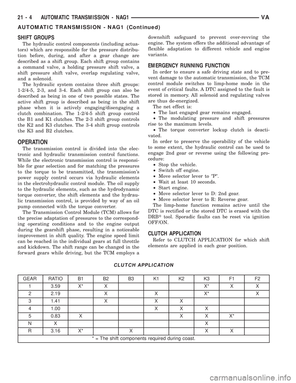
CLUTCH APPLICATION
Refer to CLUTCH APPLICATION for which shift
elements are applied in each gear position.
CLUTCH APPLICATION
GEAR RATIO B1 B2 B3 K1 K2 K3 F1 F2
1 3.59 X* X X* X X
2 2.19 X X X* X
3 1.41 X X X
4 1.00 X X X
5 0.83 X X X X*
NX X
R 3.16 X* X X X
* = The shift components required during coast.
21 - 4 AUTOMATIC TRANSMISSION - NAG1VA
AUTOMATIC TRANSMISSION - NAG1 (Continued)
Page 1133 of 1232
SPECIFICATIONS
A/C SYSTEM
The R-134a refrigerant system charge capacity for
this vehicle can be found on the underhood specifica-
tion label for the A/C unit.
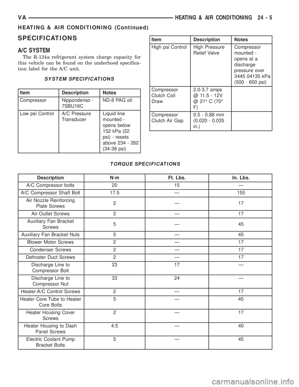
SYSTEM SPECIFICATIONS
Item Description Notes
Compressor Nippondenso -
7SBU16CND-8 PAG oil
Low psi Control A/C Pressure
TransducerLiquid line
mounted -
opens below
152 kPa (22
psi) - resets
above 234 - 262
(34-38 psi)
Item Description Notes
High psi Control High Pressure
Relief ValveCompressor
mounted -
opens at a
discharge
pressure over
3445 04135 kPa
(500 - 600 psi)
Compressor
Clutch Coil
Draw2.0-3.7 amps
@ 11.5 - 12V
@ 21É C (70É
F)
Compressor
Clutch Air Gap0.5 - 0.88 mm
(0.020 - 0.035
in.)
TORQUE SPECIFICATIONS
Description N´m Ft. Lbs. In. Lbs.
A/C Compressor bolts 20 15 Ð
A/C Compressor Shaft Bolt 17.5 Ð 155
Air Nozzle Reinforcing
Plate Screws2Ð 17
Air Outlet Screws 2 Ð 17
Auxiliary Fan Bracket
Screws5Ð 45
Auxiliary Fan Bracket Nuts 5 Ð 45
Blower Motor Screws 2 Ð 17
Condenser Screws 2 Ð 17
Defroster Duct Screws 2 Ð 17
Discharge Line to
Compressor Bolt23 17 Ð
Discharge Line to
Compressor Nut33 24 Ð
Heater-A/C Control Screws 2 Ð 17
Heater Core Tube to Heater
Core Bolts5Ð 45
Heater Housing Cover
Screws2Ð 17
Heater Housing to Dash
Panel Screws4.5 Ð 40
Electric Coolant Pump
Bracket Bolts5Ð 45
VAHEATING & AIR CONDITIONING 24 - 5
HEATING & AIR CONDITIONING (Continued)