2005 MERCEDES-BENZ SPRINTER stop start
[x] Cancel search: stop startPage 16 of 1232
JUMP STARTING
STANDARD PROCEDURE - JUMP STARTING
WARNING: REVIEW ALL SAFETY PRECAUTIONS
AND WARNINGS IN THE BATTERY SYSTEM SEC-
TION OF THE SERVICE MANUAL. (Refer to 8 -
ELECTRICAL/BATTERY SYSTEM/BATTERY - STAN-
DARD PROCEDURE)
²DO NOT JUMP START A FROZEN BATTERY,
PERSONAL INJURY CAN RESULT.
²IF EQUIPPED, DO NOT JUMP START WHEN
MAINTENANCE FREE BATTERY INDICATOR DOT IS
YELLOW OR BRIGHT COLOR.
²DO NOT JUMP START A VEHICLE WHEN THE
BATTERY FLUID IS BELOW THE TOP OF LEAD
PLATES.
²DO NOT ALLOW JUMPER CABLE CLAMPS TO
TOUCH EACH OTHER WHEN CONNECTED TO A
BOOSTER SOURCE.
²DO NOT USE OPEN FLAME NEAR BATTERY.
²REMOVE METALLIC JEWELRY WORN ON
HANDS OR WRISTS TO AVOID INJURY BY ACCI-
DENTAL ARCING OF BATTERY CURRENT.
²WHEN USING A HIGH OUTPUT BOOSTING
DEVICE, DO NOT ALLOW BATTERY VOLTAGE TO
EXCEED 16 VOLTS. REFER TO INSTRUCTIONS
PROVIDED WITH DEVICE BEING USED.
FAILURE TO FOLLOW THESE INSTRUCTIONS MAY
RESULT IN PERSONAL INJURY.
CAUTION: When using another vehicle as a
booster, do not allow vehicles to touch. Electrical
systems can be damaged on either vehicle.
TO JUMP START A DISABLED VEHICLE:
(1) Raise hood on disabled vehicle and visually
inspect engine compartment for:
²Battery cable clamp condition, clean if necessary.
²Frozen battery.
²Yellow or bright color test indicator, if equipped.
²Low battery fluid level.
²Generator drive belt condition and tension.
²Fuel fumes or leakage, correct if necessary.
CAUTION: If the cause of starting problem on dis-
abled vehicle is severe, damage to booster vehicle
charging system can result.
(2) When using another vehicle as a booster
source, park the booster vehicle within cable reach.
Turn off all accessories, set the parking brake, place
the automatic transmission in PARK or the manual
transmission in NEUTRAL and turn the ignition
OFF.(3) On disabled vehicle, place gear selector in park
or neutral and set park brake. Turn off all accesso-
ries.
(4) Connect jumper cables to booster battery. RED
clamp to positive terminal (+). BLACK clamp to neg-
ative terminal (-). DO NOT allow clamps at opposite
end of cables to touch, electrical arc will result.
Review all warnings in this procedure.
(5) On disabled vehicle, connect RED jumper cable
clamp to positive (+) terminal. Connect BLACK
jumper cable clamp to engine ground as close to the
ground cable attaching point as possible.
(6) Start the engine in the vehicle which has the
booster battery, let the engine idle a few minutes,
then start the engine in the vehicle with the dis-
charged battery.
CAUTION: Do not crank starter motor on disabled
vehicle for more than 15 seconds, starter will over-
heat and could fail.
(7) Allow battery in disabled vehicle to charge to
at least 12.4 volts (75% charge) before attempting to
start engine. If engine does not start within 15 sec-
onds, stop cranking engine and allow starter to cool
(15 min.), before cranking again.
DISCONNECT CABLE CLAMPS AS FOLLOWS:
²Disconnect BLACK cable clamp from engine
ground on disabled vehicle.
²When using a Booster vehicle, disconnect
BLACK cable clamp from battery negative terminal.
Disconnect RED cable clamp from battery positive
terminal.
²Disconnect RED cable clamp from battery posi-
tive terminal on disabled vehicle.
TOWING
STANDARD PROCEDURE - TOWING
WARNING: Do not tow the vehicle if the key cannot
be turned in the ignition lock. If the key cannot be
turned, the ignition lock remains locked and the
vehicle cannot be steered. With the engine not run-
ning there is no power assistance for the braking
and steering systems. In this case, it is important to
keep in mind that a considerably higher degree of
effort is necessary to brake and steer the vehicle.
The vehicle must not be towed with the front axle
raised and the key in position 2 in the ignition lock
as the drive wheels could then lock due to the
acceleration skid control (ASR)
0 - 6 LUBRICATION & MAINTENANCEVA
Page 42 of 1232
DRIVELINE VIBRATION
Drive Condition Possible Cause Correction
Propeller Shaft Noise 1) Undercoating or other foreign
material on shaft.1) Clean exterior of shaft and wash
with solvent.
2) Loose U-joint clamp screws. 2) Install new clamps and screws
and tighten to proper torque.
3) Loose or bent U-joint yoke or
excessive runout.3) Install new yoke.
4) Incorrect driveline angularity. 4) Measure and correct driveline
angles.
5) Rear spring center bolt not in
seat.5) Loosen spring u-bolts and seat
center bolt.
6) Worn U-joint bearings. 6) Install new U-joint.
7) Propeller shaft damaged or out
of balance.7) Installl new propeller shaft.
8) Broken rear spring. 8) Install new rear spring.
9) Excessive runout or unbalanced
condition.9) Re-index propeller shaft, test,
and evaluate.
10) Excessive drive pinion gear
shaft runout.10) Re-index propeller shaft and
evaluate.
11) Excessive axle yoke deflection. 11) Inspect and replace yoke if
necessary.
12) Excessive transfer case runout. 12) Inspect and repair as necessary.
Universal Joint Noise 1) Loose U-joint clamp screws. 1) Install new clamps and screws
and tighten to proper torque.
2) Lack of lubrication. 2) Replace as U-joints as
necessary.
PROPELLER SHAFT BALANCE
NOTE: Removing and indexing the propeller shaft
180É relative to the yoke may eliminate some vibra-
tions.
If propeller shaft is suspected of being out of bal-
ance, verify with the following procedure:
(1) Place vehicle in netrual.
(2) Raise and support the vehicle by the axles as
level as possible.
(3) Clean all foreign material from propeller shaft
and universal joints.
(4) Inspect propeller shaft for missing balance
weights, broken welds, and bent areas.
NOTE: If propeller shaft is bent, it must be replaced.
(5) Inspect universal joints for wear, properly
installed and correct alignment with the shaft.
(6) Check universal joint clamp screws torque.
(7) Remove wheels and tires. Install wheel lug
nuts to retain the brake drums/rotors.(8) Mark and number propeller shaft six inches
from the pinion yoke end at four positions 90É apart.
(9) Run and accelerate the vehicle until vibration
occurs. Note intensity and speed the vibration
occurred. Stop the engine.
(10) Install a screw clamp at position 1 (Fig. 1).
(11) Start engine and re-check for vibration. If lit-
tle or no change in vibration is evident, move clamp
to the next positions and repeat vibration test.
NOTE: If there is no difference in vibration at the
other positions, the vibration may not be propeller
shaft.
(12) If vibration decreased, install a second clamp
(Fig. 2) and repeat vibration test.
(13) If additional clamp causes additional vibra-
tion, separate clamps 1/2 inch above and below the
mark. Repeat the vibration test (Fig. 3).
(14) Increase distance between clamps and repeat
test until vibration is at the lowest level. Bend the
slack end of the clamps so the screws will not loosen.
3 - 2 PROPELLER SHAFTVA
PROPELLER SHAFT (Continued)
Page 68 of 1232
A worn, damaged wheel bearing or suspension
component are further causes of pull. A damaged
front tire (bruised, ply separation) can also cause
pull.
A common and frequently misdiagnosed pull condi-
tion is where direction of pull changes after a few
stops. The cause is a combination of brake drag fol-
lowed by fade at one of the brake units.
As the dragging brake overheats, efficiency is so
reduced that fade occurs. Since the opposite brake
unit is still functioning normally, its braking effect is
magnified. This causes pull to switch direction in
favor of the normally functioning brake unit.
An additional point when diagnosing a change in
pull condition concerns brake cool down. Remember
that pull will return to the original direction, if the
dragging brake unit is allowed to cool down (and is
not seriously damaged).
REAR BRAKE GRAB OR PULL
Rear grab or pull is usually caused by improperly
adjusted or seized parking brake cables, contami-
nated lining, bent or binding shoes and support
plates, or improperly assembled components. This is
particularly true when only one rear wheel is
involved. However, when both rear wheels are
affected, the master cylinder or proportioning valve
could be at fault.
BRAKES DO NOT HOLD AFTER DRIVING THROUGH DEEP
WATER PUDDLES
This condition is generally caused by water soaked
lining. If the lining is only wet, it can be dried by
driving with the brakes very lightly applied for a
mile or two. However, if the lining is both soaked and
dirt contaminated, cleaning and/or replacement will
be necessary.
BRAKE LINING CONTAMINATION
Brake lining contamination is mostly a product of
leaking calipers or worn seals, driving through deep
water puddles, or lining that has become covered
with grease and grit during repair. Contaminated lin-
ing should be replaced to avoid further brake prob-
lems.
WHEEL AND TIRE PROBLEMS
Some conditions attributed to brake components
may actually be caused by a wheel or tire problem.
A damaged wheel can cause shudder, vibration and
pull. A worn or damaged tire can also cause pull.
Severely worn tires with very little tread left can
produce a grab-like condition as the tire loses and
recovers traction. Flat-spotted tires can cause vibra-
tion and generate shudder during brake operation. A
tire with internal damage such as a severe bruise,
cut, or ply separation can cause pull and vibration.BRAKE NOISES
Some brake noise is common with rear drum
brakes and on some disc brakes during the first few
stops after a vehicle has been parked overnight or
stored. This is primarily due to the formation of trace
corrosion (light rust) on metal surfaces. This light
corrosion is typically cleared from the metal surfaces
after a few brake applications causing the noise to
subside.
BRAKE SQUEAK/SQUEAL
Brake squeak or squeal may be due to linings that
are wet or contaminated with brake fluid, grease, or
oil. Glazed linings and rotors with hard spots can
also contribute to squeak. Dirt and foreign material
embedded in the brake lining will also cause squeak/
squeal.
A very loud squeak or squeal is frequently a sign of
severely worn brake lining. If the lining has worn
through to the brake pads in spots, metal-to-metal
contact occurs. If the condition is allowed to continue,
rotors can become so scored that replacement is nec-
essary.
BRAKE CHATTER
Brake chatter is usually caused by loose or worn
components, or glazed/burnt lining. Rotors with hard
spots can also contribute to chatter. Additional causes
of chatter are out-of-tolerance rotors, brake lining not
securely attached to the shoes, loose wheel bearings
and contaminated brake lining.
THUMP/CLUNK NOISE
Thumping or clunk noises during braking are fre-
quentlynotcaused by brake components. In many
cases, such noises are caused by loose or damaged
steering, suspension, or engine components. However,
calipers that bind on the slide surfaces can generate
a thump or clunk noise.
STANDARD PROCEDURE
STANDARD PROCEDURE - MANUAL BLEEDING
Use Mopar brake fluid, or an equivalent quality
fluid meeting SAE and DOT 4 standards only. Use
fresh, clean fluid from a sealed container at all times.
(1) Remove reservoir filler caps and fill reservoir.
(2) If calipers, or wheel cylinders were overhauled,
open all caliper and wheel cylinder bleed screws.
Then close each bleed screw as fluid starts to drip
from it. Top off master cylinder reservoir once more
before proceeding.
(3) Attach one end of bleed hose to bleed screw
and insert opposite end in glass container partially
filled with brake fluid (Fig. 1). Be sure end of bleed
hose is immersed in fluid.
5 - 4 BRAKES - BASEVA
BRAKES - BASE (Continued)
Page 80 of 1232
(8) Raise the vehicle and adjust the ALB controller
(Refer to 5 - BRAKES/HYDRAULIC/MECHANICAL/
ALB CONTROLLER - ADJUSTMENTS).
(9) Lower the vehicle and test drive.
ADJUSTMENTS
ADJUSTMENT
(1) Clean any debris away from the test ports caps
at the ALB controller.
(2) Connect brake adapters special tool 9297 to the
test ports at the ALB controller.
(3) Install a Pressure Gauge, Special Tool
C-4007-A, to the adapters.
(4) Tighten all tube nut fittings to 17 N´m (145 in.
lbs.) torque.
(5) Bleed any air out of the system. This includes
bleeding the air from the hose between the pressure
test fitting and pressure gauge, which is done at the
pressure gauge.
NOTE: Adjustment is determined for the automatic
load-dependent brake power control system accord-
ing to the ALB plate. This is housed in the stowage
compartment under the front passenger's door
panel. The part number of the rear spring is
stamped into the spring eye. This must correspond
to the part number of the rear spring on the ALB
plate.
(6) To accurately adjust the rear axle load you
must first determine the rear axle load by weighing
the vehicle at a local scale.
(7) Install the brake pedal winch Special tool 9296
between the brake pedal and the driver seat and
slowly turn the dial until the specified inlet brake
pressure is indicated at the gauge.
NOTE: The pressure gauge, connected at the ALB
controller must indicate the outlet pressure which
is assigned on the ALB plate to the rear axle load
determined.
NOTE: If the rear axle load determined is between
two figures indicated on the ALB plate, the outlet
pressure should be determined accordingly.
(8) If the pressure measured differs from the spec-
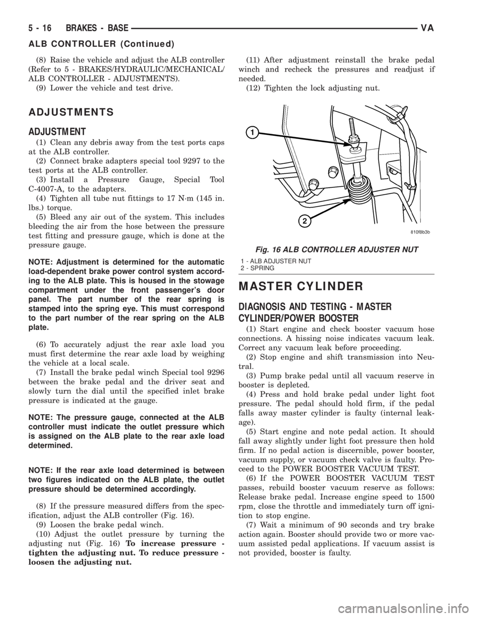
ification, adjust the ALB controller (Fig. 16).
(9) Loosen the brake pedal winch.
(10) Adjust the outlet pressure by turning the
adjusting nut (Fig. 16)To increase pressure -
tighten the adjusting nut. To reduce pressure -
loosen the adjusting nut.(11) After adjustment reinstall the brake pedal
winch and recheck the pressures and readjust if
needed.
(12) Tighten the lock adjusting nut.
MASTER CYLINDER
DIAGNOSIS AND TESTING - MASTER
CYLINDER/POWER BOOSTER
(1) Start engine and check booster vacuum hose
connections. A hissing noise indicates vacuum leak.
Correct any vacuum leak before proceeding.
(2) Stop engine and shift transmission into Neu-
tral.
(3) Pump brake pedal until all vacuum reserve in
booster is depleted.
(4) Press and hold brake pedal under light foot
pressure. The pedal should hold firm, if the pedal
falls away master cylinder is faulty (internal leak-
age).
(5) Start engine and note pedal action. It should
fall away slightly under light foot pressure then hold
firm. If no pedal action is discernible, power booster,
vacuum supply, or vacuum check valve is faulty. Pro-
ceed to the POWER BOOSTER VACUUM TEST.
(6) If the POWER BOOSTER VACUUM TEST
passes, rebuild booster vacuum reserve as follows:
Release brake pedal. Increase engine speed to 1500
rpm, close the throttle and immediately turn off igni-
tion to stop engine.
(7) Wait a minimum of 90 seconds and try brake
action again. Booster should provide two or more vac-
uum assisted pedal applications. If vacuum assist is
not provided, booster is faulty.
Fig. 16 ALB CONTROLLER ADJUSTER NUT
1 - ALB ADJUSTER NUT
2 - SPRING
5 - 16 BRAKES - BASEVA
ALB CONTROLLER (Continued)
Page 81 of 1232
POWER BOOSTER VACUUM TEST
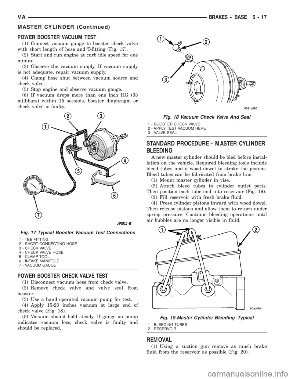
(1) Connect vacuum gauge to booster check valve
with short length of hose and T-fitting (Fig. 17).
(2) Start and run engine at curb idle speed for one
minute.
(3) Observe the vacuum supply. If vacuum supply
is not adequate, repair vacuum supply.
(4) Clamp hose shut between vacuum source and
check valve.
(5) Stop engine and observe vacuum gauge.
(6) If vacuum drops more than one inch HG (33
millibars) within 15 seconds, booster diaphragm or
check valve is faulty.
POWER BOOSTER CHECK VALVE TEST
(1) Disconnect vacuum hose from check valve.
(2) Remove check valve and valve seal from
booster.
(3) Use a hand operated vacuum pump for test.
(4) Apply 15-20 inches vacuum at large end of
check valve (Fig. 18).
(5) Vacuum should hold steady. If gauge on pump
indicates vacuum loss, check valve is faulty and
should be replaced.
STANDARD PROCEDURE - MASTER CYLINDER
BLEEDING
A new master cylinder should be bled before instal-
lation on the vehicle. Required bleeding tools include
bleed tubes and a wood dowel to stroke the pistons.
Bleed tubes can be fabricated from brake line.
(1) Mount master cylinder in vise.
(2) Attach bleed tubes to cylinder outlet ports.
Then position each tube end into reservoir (Fig. 19).
(3) Fill reservoir with fresh brake fluid.
(4) Press cylinder pistons inward with wood dowel.
Then release pistons and allow them to return under
spring pressure. Continue bleeding operations until
air bubbles are no longer visible in fluid.
REMOVAL
(1) Using a suction gun remove as much brake
fluid from the reservoir as possible (Fig. 20).
Fig. 17 Typical Booster Vacuum Test Connections
1 - TEE FITTING
2 - SHORT CONNECTING HOSE
3 - CHECK VALVE
4 - CHECK VALVE HOSE
5 - CLAMP TOOL
6 - INTAKE MANIFOLD
7 - VACUUM GAUGE
Fig. 18 Vacuum Check Valve And Seal
1 - BOOSTER CHECK VALVE
2 - APPLY TEST VACUUM HERE
3 - VALVE SEAL
Fig. 19 Master Cylinder Bleeding±Typical
1 - BLEEDING TUBES
2 - RESERVOIR
VABRAKES - BASE 5 - 17
MASTER CYLINDER (Continued)
Page 106 of 1232
acteristics than ethylene glycol. This can increase
cylinder head temperatures under certain conditions.
Propylene-glycol/Ethylene-glycol MixturesÐShould Not Be
Used in Chrysler Vehicles
Propylene-glycol/ethylene-glycol Mixtures can
cause the destabilization of various corrosion inhibi-
tors, causing damage to the various cooling system
components. Also, once ethylene-glycol and propy-
lene-glycol based coolants are mixed in the vehicle,
conventional methods of determining freeze point will
not be accurate. Both the refractive index and spe-
cific gravity differ between ethylene glycol and propy-
lene glycol.
CAUTION: Richer antifreeze mixtures cannot be
measured with normal field equipment and can
cause problems associated with 100 percent ethyl-
ene-glycol.
DIAGNOSIS AND TESTING - COOLING SYSTEM
LEAKS
ULTRAVIOLET LIGHT METHOD
A leak detection additive is available through the
parts department that can be added to cooling sys-
tem. The additive is highly visible under ultraviolet
light (black light). Pour one ounce of additive into
cooling system. Place heater control unit in HEAT
position. Start and operate engine until radiator
upper hose is warm to touch. Aim the commercially
available black light tool at components to be
checked. If leaks are present, black light will cause
additive to glow a bright green color.
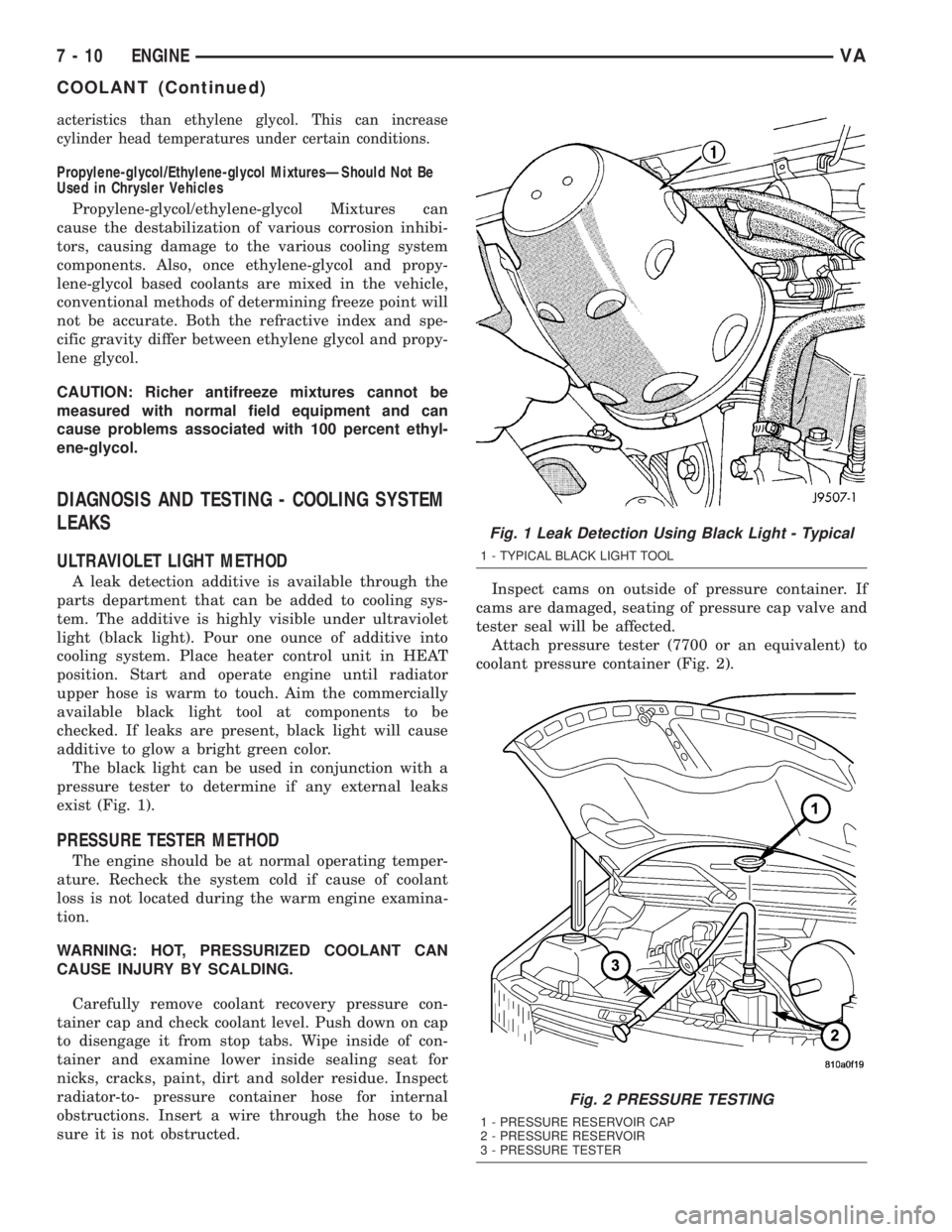
The black light can be used in conjunction with a
pressure tester to determine if any external leaks
exist (Fig. 1).
PRESSURE TESTER METHOD
The engine should be at normal operating temper-
ature. Recheck the system cold if cause of coolant
loss is not located during the warm engine examina-
tion.
WARNING: HOT, PRESSURIZED COOLANT CAN
CAUSE INJURY BY SCALDING.
Carefully remove coolant recovery pressure con-
tainer cap and check coolant level. Push down on cap
to disengage it from stop tabs. Wipe inside of con-
tainer and examine lower inside sealing seat for
nicks, cracks, paint, dirt and solder residue. Inspect
radiator-to- pressure container hose for internal
obstructions. Insert a wire through the hose to be
sure it is not obstructed.Inspect cams on outside of pressure container. If
cams are damaged, seating of pressure cap valve and
tester seal will be affected.
Attach pressure tester (7700 or an equivalent) to
coolant pressure container (Fig. 2).
Fig. 1 Leak Detection Using Black Light - Typical
1 - TYPICAL BLACK LIGHT TOOL
Fig. 2 PRESSURE TESTING
1 - PRESSURE RESERVOIR CAP
2 - PRESSURE RESERVOIR
3 - PRESSURE TESTER
7 - 10 ENGINEVA
COOLANT (Continued)
Page 201 of 1232
²Trailer Tow Connector- Vehicles equipped
with a factory-approved, field-installed trailer towing
electrical package have a heavy duty 7-way trailer
tow connector installed in a bracket on the trailer
hitch receiver. This package includes a 7-way to
4-way connector adapter unit.
²Trailer Tow Control Module- Vehicles
equipped with a factory-approved, field-installed
trailer towing electrical package have a trailer tow
brake/turn control module located within the driver
side front seat riser that controls the brake lamp and
turn signal lamp outputs to the trailer lighting cir-
cuits.
²Turn Signal Relay- A turn signal relay is
installed in the fuse block located on the underside of
the steering column behind a fuse access panel in the
steering column opening cover on the instrument
panel. The electronic circuitry of the wipers, turn sig-
nals and engine start control module within the fuse
block controls the turn signal relay.
²Wipers, Turn Signals, Engine Start Control
Module- The wipers, turn signals and engine start
control module is integral to the fuse block located on
the underside of the steering column behind a fuse
access panel in the steering column opening cover on
the instrument panel. This module includes active
electronic elements that control the operation of the
turn signal relay based upon inputs from the multi-
function switch and feedback from the turn signal
circuits. (Refer to 8 - ELECTRICAL/POWER DISTRI-
BUTION/FUSE BLOCK - DESCRIPTION).
Hard wired circuitry connects the exterior lighting
system components to the electrical system of the
vehicle. These hard wired circuits are integral to sev-
eral wire harnesses, which are routed throughout the
vehicle and retained by many different methods.
These circuits may be connected to each other, to the
vehicle electrical system and to the exterior lighting
system components through the use of a combination
of soldered splices, splice block connectors, and many
different types of wire harness terminal connectors
and insulators. Refer to the appropriate wiring infor-
mation. The wiring information includes wiring dia-
grams, proper wire and connector repair procedures,
further details on wire harness routing and reten-
tion, as well as pin-out and location views for the
various wire harness connectors, splices and grounds.
OPERATION
Following are paragraphs that briefly describe the
operation of each of the major exterior lighting sys-
tems. The hard wired circuits and components of the
exterior lighting systems may be diagnosed and
tested using conventional diagnostic tools and proce-
dures. However, conventional diagnostic methods
may not prove conclusive in the diagnosis of the wip-ers, turn signals and engine start control module
located within the fuse block underneath the steering
column, the ElectroMechanical Instrument Cluster
(EMIC), the Engine Control Module (ECM), or the
Controller Area Network (CAN) data bus network.
The most reliable, efficient, and accurate means to
diagnose the electronic module within the fuse block,
the EMIC, the ECM, and the CAN data bus network
inputs and outputs related to the various exterior
lighting systems requires the use of a DRBIIItscan
tool. Refer to the appropriate diagnostic information.
BACKUP LAMPS
The backup (or reverse) lamps have a path to
ground received at all times through the vehicle wire
harness from a ground point located on the frame
near the left end of the tailgate sill. The backup
lamps receive battery current on the backup lamp
supply circuit only when the backup lamp switch cir-
cuit of the Transmission Range Sensor (TRS) integral
to the gear shifter assembly is closed by the gear
shifter mechanism.
BRAKE LAMPS
The brake (or stop) lamps have a path to ground at
all times through the vehicle wire harness from a
ground point located on the frame near the left end
of the tailgate sill. The Center High Mounted Stop
Lamp (CHMSL) has a path to ground at all times
through the vehicle wire harness from a ground point
on the left side of the dash panel. The brake lamps
and CHMSL receive battery current on the brake
lamp switch output circuit when the brake lamp
switch is closed by the brake pedal arm.
DAYTIME RUNNING LAMPS
Vehicles manufactured for sale in Canada illumi-
nate the low beam headlamp bulb when the engine is
running and the exterior lamps are turned off. This
feature is enabled by the right and left Daytime Run-
ning Lamps (DRL) relays. When the DRL relays are
de-energized, they provide fused battery current from
the circuit K26 relay to the headlamp low beams.
When the headlamps are turned On using the left
(lighting) control stalk of the multi-function switch
the DRL relays are energized, which returns control
of the headlamps to the headlamp switch circuitry of
the multi-function switch. The circuit K26 relay is
energized by the Electro-Mechanical Instrument
Cluster (EMIC) whenever it receives an electronic
message from the Engine Control Module (ECM) over
the Controller Area Network (CAN) data bus indicat-
ing that the engine is running. The DRL and circuit
K26 relays are installed in a relay bracket located
below the forward edge of the driver side front seat
cushion within the driver side front seat riser.
VALAMPS/LIGHTING - EXTERIOR 8L - 3
LAMPS/LIGHTING - EXTERIOR (Continued)
Page 203 of 1232
system illuminates the selected right or left turn sig-
nal indicator and the turn signal lamps begin to
flash. The turn signal lamps include a bulb integral
to each front lamp unit and each tail lamp unit, as
well as a repeater lamp bulb located on each front
fender above the front wheels. When the turn signal
system is activated, the turn signal switch circuitry
within the multi-function switch and the electronic
circuitry of the wipers, turn signals and engine start
control module within the fuse block will repeatedly
energize and de-energize the turn signal relay
located in the fuse block. The turn signal relay
switches battery current from a fused ignition switch
output fuse in the fuse block to the appropriate turn
signal indicator and turn signal lamps.
The ElectroMechanical Instrument Cluster (EMIC)
contactless relay will generate repetitive, audible
turn signal ªclickº sounds to emulate the sounds of a
conventional electro-mechanical turn signal flasher
at one of two rates to coincide with the flashing of
the turn signals. The slow rate emulates normal turn
signal operation, while the fast rate emulates ªbulb
outº turn signal operation.
SPECIFICATIONS - LAMPS/LIGHTING -
EXTERIOR
BULB SPECIFICATIONS
LAMP BULB
Backup P21W - 12V 21W
Brake & Rear Park P21/5W - 12V 21/5W
Center High Mounted
StopP21W - 12V 21W
Clearance W3W - 12V 3W
Front Fog H1 - 12V 55W
Front Position W5W - 12V 5W
Front Turn, Park & Side
Marker3457 NA - 12V 28/7.5W
Amber Glass
Low Beam Headlamp H7 - 12V 55W
High Beam Headlamp H1 - 12V 55W
License Plate C5W - 12V 5W
Rear Side Marker R5W - 12V 5W
Rear Turn P21W - 12V 21W
Side Repeater W5W - 12V 3W
BACKUP LAMP BULB
REMOVAL
(1) Disconnect and isolate the battery negative
cable.(2) If the vehicle is so equipped, remove the trim
from the inside of the right or left rear corner pillar.
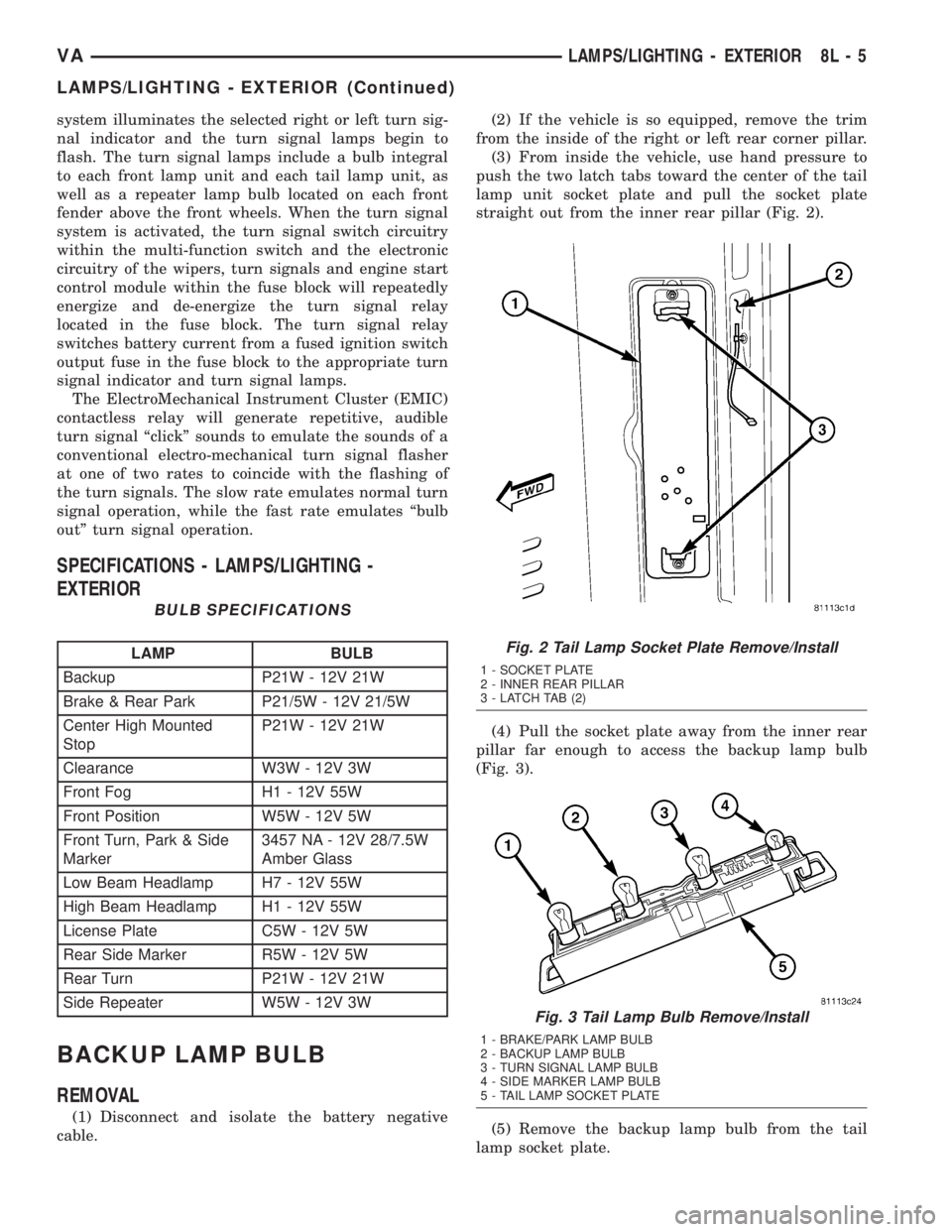
(3) From inside the vehicle, use hand pressure to
push the two latch tabs toward the center of the tail
lamp unit socket plate and pull the socket plate
straight out from the inner rear pillar (Fig. 2).
(4) Pull the socket plate away from the inner rear
pillar far enough to access the backup lamp bulb
(Fig. 3).
(5) Remove the backup lamp bulb from the tail
lamp socket plate.
Fig. 2 Tail Lamp Socket Plate Remove/Install
1 - SOCKET PLATE
2 - INNER REAR PILLAR
3 - LATCH TAB (2)
Fig. 3 Tail Lamp Bulb Remove/Install
1 - BRAKE/PARK LAMP BULB
2 - BACKUP LAMP BULB
3 - TURN SIGNAL LAMP BULB
4 - SIDE MARKER LAMP BULB
5 - TAIL LAMP SOCKET PLATE
VALAMPS/LIGHTING - EXTERIOR 8L - 5
LAMPS/LIGHTING - EXTERIOR (Continued)