2005 MERCEDES-BENZ SPRINTER stop start
[x] Cancel search: stop startPage 880 of 1232
SHIFT GROUPS
The hydraulic control components (including actua-
tors) which are responsible for the pressure distribu-
tion before, during, and after a gear change are
described as a shift group. Each shift group contains
a command valve, a holding pressure shift valve, a
shift pressure shift valve, overlap regulating valve,
and a solenoid.
The hydraulic system contains three shift groups:
1-2/4-5, 2-3, and 3-4. Each shift group can also be
described as being in one of two possible states. The
active shift group is described as being in the shift
phase when it is actively engaging/disengaging a
clutch combination. The 1-2/4-5 shift group control
the B1 and K1 clutches. The 2-3 shift group controls
the K2 and K3 clutches. The 3-4 shift group controls
the K3 and B2 clutches.
OPERATION
The transmission control is divided into the elec-
tronic and hydraulic transmission control functions.
While the electronic transmission control is responsi-
ble for gear selection and for matching the pressures
to the torque to be transmitted, the transmission's
power supply control occurs via hydraulic elements
in the electrohydraulic control module. The oil supply
to the hydraulic elements, such as the hydrodynamic
torque converter, the shift elements and the hydrau-
lic transmission control, is provided by way of an oil
pump connected with the torque converter.
The Transmission Control Module (TCM) allows for
the precise adaptation of pressures to the correspond-
ing operating conditions and to the engine output
during the gearshift phase, resulting in a noticeable
improvement in shift quality. The engine speed limit
can be reached in the individual gears at full throttle
and kickdown. The shift range can be changed in the
forward gears while driving, but the TCM employs adownshift safeguard to prevent over-revving the
engine. The system offers the additional advantage of
flexible adaptation to different vehicle and engine
variants.
EMERGENCY RUNNING FUNCTION
In order to ensure a safe driving state and to pre-
vent damage to the automatic transmission, the TCM
control module switches to limp-home mode in the
event of critical faults. A DTC assigned to the fault is
stored in memory. All solenoid and regulating valves
are thus de-energized.
The net effect is:
²The last engaged gear remains engaged.
²The modulating pressure and shift pressures
rise to the maximum levels.
²The torque converter lockup clutch is deacti-
vated.
In order to preserve the operability of the vehicle
to some extent, the hydraulic control can be used to
engage 2nd gear or reverse using the following pro-
cedure:
²Stop the vehicle.
²Switch off engine.
²Move selector lever to9P9.
²Wait at least 10 seconds.
²Start engine.
²Move selector lever to D: 2nd gear.
²Move selector lever to R: Reverse gear.
The limp-home function remains active until the
DTC is rectified or the stored DTC is erased with the
DRBttool. Sporadic faults can be reset via ignition
OFF/ON.
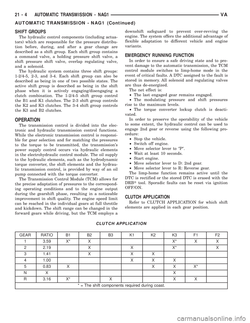
CLUTCH APPLICATION
Refer to CLUTCH APPLICATION for which shift
elements are applied in each gear position.
CLUTCH APPLICATION
GEAR RATIO B1 B2 B3 K1 K2 K3 F1 F2
1 3.59 X* X X* X X
2 2.19 X X X* X
3 1.41 X X X
4 1.00 X X X
5 0.83 X X X X*
NX X
R 3.16 X* X X X
* = The shift components required during coast.
21 - 4 AUTOMATIC TRANSMISSION - NAG1VA
AUTOMATIC TRANSMISSION - NAG1 (Continued)
Page 899 of 1232
DIAGNOSIS AND TESTING
DIAGNOSIS AND TESTING - AUTOMATIC
TRANSMISSION
CAUTION: Before attempting any repair on a NAG1
automatic transmission, check for Diagnostic Trou-
ble Codes with the DRBTscan tool.
Transmission malfunctions may be caused by these
general conditions:
²Poor engine performance.
²Improper adjustments.
²Hydraulic malfunctions.
²Mechanical malfunctions.
²Electronic malfunctions.
²Transfer case performance.
Diagnosis of these problems should always begin
by checking the easily accessible variables: fluid level
and condition, gearshift cable adjustment. Then per-
form a road test to determine if the problem has been
corrected or if more diagnosis is necessary.
DIAGNOSIS AND TESTING - PRELIMINARY
Two basic procedures are required. One procedure
for vehicles that are drivable and an alternate proce-
dure for disabled vehicles (will not back up or move
forward).
VEHICLE IS DRIVABLE
(1) Check for transmission fault codes using DRBt
scan tool.
(2) Check fluid level and condition.
(3) Adjust gearshift cable if complaint was based
on delayed, erratic, or harsh shifts.
(4) Road test and note how transmission upshifts,
downshifts, and engages.
VEHICLE IS DISABLED
(1) Check fluid level and condition.(2) Check for broken or disconnected gearshift
cable.
(3) Check for cracked, leaking cooler lines, or loose
or missing pressure-port plugs.
(4) Raise and support vehicle on safety stands,
start engine, shift transmission into gear, and note
following:
(a) If propeller shaft turns but wheels do not,
problem is with differential or axle shafts.
(b) If propeller shaft does not turn and transmis-
sion is noisy, stop engine. Remove oil pan, and
check for debris. If pan is clear, remove transmis-
sion and check for damaged driveplate, converter,
oil pump, or input shaft.
(c) If propeller shaft does not turn and transmis-
sion is not noisy, perform hydraulic-pressure test to
determine if problem is hydraulic or mechanical.
DIAGNOSIS AND TESTING - ROAD TESTING
Before road testing, be sure the fluid level and con-
trol cable adjustments have been checked and
adjusted if necessary. Verify that all diagnostic trou-
ble codes have been resolved.
Observe engine performance during the road test.
A poorly tuned engine will not allow accurate analy-
sis of transmission operation.
Operate the transmission in all gear ranges. Check
for shift variations and engine flare which indicates
slippage. Note if shifts are harsh, spongy, delayed,
early, or if part throttle downshifts are sensitive.
Slippage indicated by engine flare, usually means
clutch, overrunning clutch, or line pressure problems.
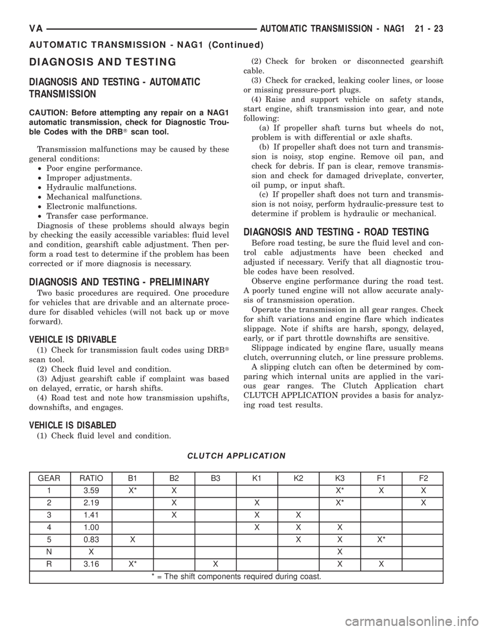
A slipping clutch can often be determined by com-
paring which internal units are applied in the vari-
ous gear ranges. The Clutch Application chart
CLUTCH APPLICATION provides a basis for analyz-
ing road test results.
CLUTCH APPLICATION
GEAR RATIO B1 B2 B3 K1 K2 K3 F1 F2
1 3.59 X* X X* X X
2 2.19 X X X* X
3 1.41 X X X
4 1.00 X X X
5 0.83 X X X X*
NX X
R 3.16 X* X X X
* = The shift components required during coast.
VAAUTOMATIC TRANSMISSION - NAG1 21 - 23
AUTOMATIC TRANSMISSION - NAG1 (Continued)
Page 900 of 1232
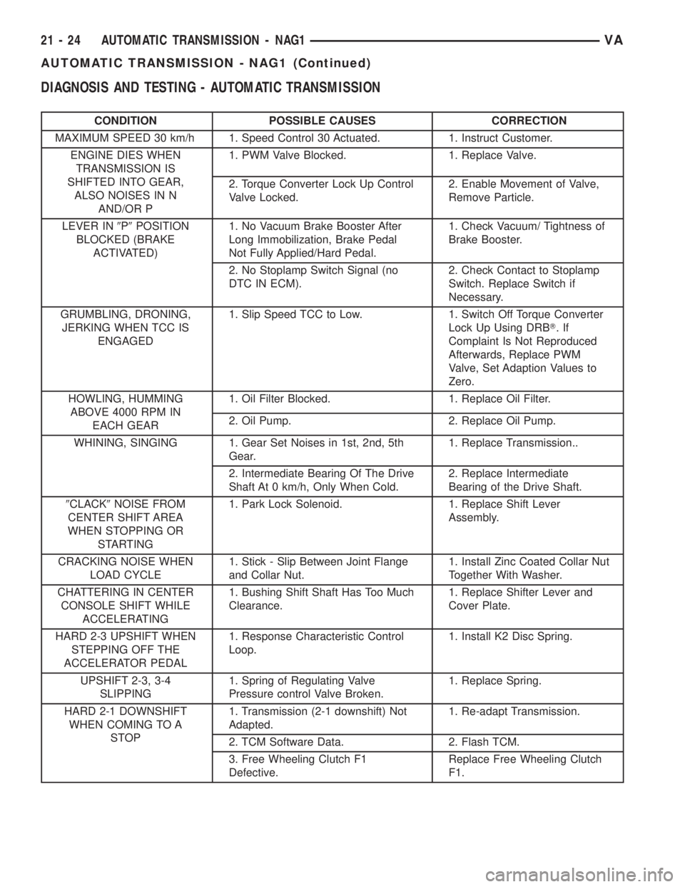
DIAGNOSIS AND TESTING - AUTOMATIC TRANSMISSION
CONDITION POSSIBLE CAUSES CORRECTION
MAXIMUM SPEED 30 km/h 1. Speed Control 30 Actuated. 1. Instruct Customer.
ENGINE DIES WHEN
TRANSMISSION IS
SHIFTED INTO GEAR,
ALSO NOISES IN N
AND/OR P1. PWM Valve Blocked. 1. Replace Valve.
2. Torque Converter Lock Up Control
Valve Locked.2. Enable Movement of Valve,
Remove Particle.
LEVER IN9P9POSITION
BLOCKED (BRAKE
ACTIVATED)1. No Vacuum Brake Booster After
Long Immobilization, Brake Pedal
Not Fully Applied/Hard Pedal.1. Check Vacuum/ Tightness of
Brake Booster.
2. No Stoplamp Switch Signal (no
DTC IN ECM).2. Check Contact to Stoplamp
Switch. Replace Switch if
Necessary.
GRUMBLING, DRONING,
JERKING WHEN TCC IS
ENGAGED1. Slip Speed TCC to Low. 1. Switch Off Torque Converter
Lock Up Using DRBT.If
Complaint Is Not Reproduced
Afterwards, Replace PWM
Valve, Set Adaption Values to
Zero.
HOWLING, HUMMING
ABOVE 4000 RPM IN
EACH GEAR1. Oil Filter Blocked. 1. Replace Oil Filter.
2. Oil Pump. 2. Replace Oil Pump.
WHINING, SINGING 1. Gear Set Noises in 1st, 2nd, 5th
Gear.1. Replace Transmission..
2. Intermediate Bearing Of The Drive
Shaft At 0 km/h, Only When Cold.2. Replace Intermediate
Bearing of the Drive Shaft.
9CLACK9NOISE FROM
CENTER SHIFT AREA
WHEN STOPPING OR
STARTING1. Park Lock Solenoid. 1. Replace Shift Lever
Assembly.
CRACKING NOISE WHEN
LOAD CYCLE1. Stick - Slip Between Joint Flange
and Collar Nut.1. Install Zinc Coated Collar Nut
Together With Washer.
CHATTERING IN CENTER
CONSOLE SHIFT WHILE
ACCELERATING1. Bushing Shift Shaft Has Too Much
Clearance.1. Replace Shifter Lever and
Cover Plate.
HARD 2-3 UPSHIFT WHEN
STEPPING OFF THE
ACCELERATOR PEDAL1. Response Characteristic Control
Loop.1. Install K2 Disc Spring.
UPSHIFT 2-3, 3-4
SLIPPING1. Spring of Regulating Valve
Pressure control Valve Broken.1. Replace Spring.
HARD 2-1 DOWNSHIFT
WHEN COMING TO A
STOP1. Transmission (2-1 downshift) Not
Adapted.1. Re-adapt Transmission.
2. TCM Software Data. 2. Flash TCM.
3. Free Wheeling Clutch F1
Defective.Replace Free Wheeling Clutch
F1.
21 - 24 AUTOMATIC TRANSMISSION - NAG1VA
AUTOMATIC TRANSMISSION - NAG1 (Continued)
Page 979 of 1232
(4) Actuate the service brake. Start engine and let
it run at idle speed in selector lever position9P9.
(5) Shift through the transmission modes several
times with the vehicle stationary and the engine
idling
(6) Warm up the transmission, wait at least 2 min-
utes and check the oil level with the engine running.
Push the Oil Dipstick 8863A in up to the stop on the
electrohydraulic unit and pull out again, read off oil
level, repeat if necessary.
NOTE: The dipstick will protrude from the fill tube
approximately 75mm (3 inches) when installed.
(7) Check transmission oil temperature.
NOTE: The true transmission oil temperature can
only be read by a scan tool in REVERSE or any for-
ward gear position. (Refer to 21 - AUTOMATIC
TRANSMISSION- NAG1/TRANSMISSION TEMPERA-
TURE SENSOR/PARK-NEUTRAL SWITCH - OPERA-
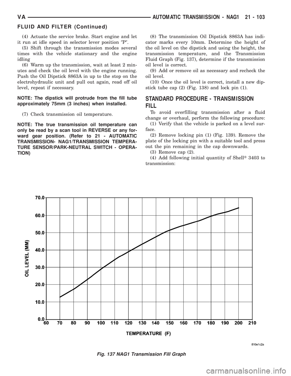
TION)(8) The transmission Oil Dipstick 8863A has indi-
cator marks every 10mm. Determine the height of
the oil level on the dipstick and using the height, the
transmission temperature, and the Transmission
Fluid Graph (Fig. 137), determine if the transmission
oil level is correct.
(9) Add or remove oil as necessary and recheck the
oil level.
(10) Once the oil level is correct, install a new dip-
stick tube cap (2) (Fig. 138) and lock pin (1).
STANDARD PROCEDURE - TRANSMISSION
FILL
To avoid overfilling transmission after a fluid
change or overhaul, perform the following procedure:
(1) Verify that the vehicle is parked on a level sur-
face.
(2) Remove locking pin (1) (Fig. 139). Remove the
plate of the locking pin with a suitable tool and press
out the pin remaining in the cap downwards.
(3) Remove cap (2).
(4) Add following initial quantity of Shellt3403 to
transmission:
Fig. 137 NAG1 Transmission Fill Graph
VAAUTOMATIC TRANSMISSION - NAG1 21 - 103
FLUID AND FILTER (Continued)
Page 1040 of 1232
VISUAL INSPECTION BEFORE WATER LEAK TESTS
Verify that floor and body plugs are in place, body
drains are clear, and body components are properly
aligned and sealed. If component alignment or seal-
ing is necessary, refer to the appropriate section of
this group for proper procedures.
WATER LEAK TESTS
WARNING: DO NOT USE ELECTRIC SHOP LIGHTS
OR TOOLS IN WATER TEST AREA. PERSONAL
INJURY CAN RESULT.
When the conditions causing a water leak have
been determined, simulate the conditions as closely
as possible.
²If a leak occurs with the vehicle parked in a
steady light rain, flood the leak area with an open-
ended garden hose.
²If a leak occurs while driving at highway speeds
in a steady rain, test the leak area with a reasonable
velocity stream or fan spray of water. Direct the
spray in a direction comparable to actual conditions.
²If a leak occurs when the vehicle is parked on an
incline, hoist the end or side of the vehicle to simu-
late this condition. This method can be used when
the leak occurs when the vehicle accelerates, stops or
turns. If the leak occurs on acceleration, hoist the
front of the vehicle. If the leak occurs when braking,
hoist the back of the vehicle. If the leak occurs on left
turns, hoist the left side of the vehicle. If the leak
occurs on right turns, hoist the right side of the vehi-
cle. For hoisting recommendations (Refer to LUBRI-
CATION & MAINTENANCE/HOISTING -
STANDARD PROCEDURE).
WATER LEAK DETECTION
To detect a water leak point-of-entry, do a water
test and watch for water tracks or droplets forming
on the inside of the vehicle. If necessary, remove inte-
rior trim covers or panels to gain visual access to the
leak area. If the hose cannot be positioned without
being held, have someone help do the water test.
Some water leaks must be tested for a considerable
length of time to become apparent. When a leak
appears, find the highest point of the water track or
drop. The highest point usually will show the point of
entry. After leak point has been found, repair the
leak and water test to verify that the leak has
stopped.
Locating the entry point of water that is leaking
into a cavity between panels can be difficult. The
trapped water may splash or run from the cavity,
often at a distance from the entry point. Most water
leaks of this type become apparent after accelerating,
stopping, turning, or when on an incline.MIRROR INSPECTION METHOD
When a leak point area is visually obstructed, use
a suitable mirror to gain visual access. A mirror can
also be used to deflect light to a limited-access area
to assist in locating a leak point.
BRIGHT LIGHT LEAK TEST METHOD
Some water leaks in the luggage compartment can
be detected without water testing. Position the vehi-
cle in a brightly lit area. From inside the darkened
luggage compartment inspect around seals and body
seams. If necessary, have a helper direct a drop light
over the suspected leak areas around the luggage
compartment. If light is visible through a normally
sealed location, water could enter through the open-
ing.
PRESSURIZED LEAK TEST METHOD
When a water leak into the passenger compart-
ment cannot be detected by water testing, pressurize
the passenger compartment and soap test exterior of
the vehicle. To pressurize the passenger compart-
ment, close all doors and windows, start engine, and
set heater control to high blower in HEAT position. If
engine can not be started, connect a charger to the
battery to ensure adequate voltage to the blower.
With interior pressurized, apply dish detergent solu-
tion to suspected leak area on the exterior of the
vehicle. Apply detergent solution with spray device or
soft bristle brush. If soap bubbles occur at a body
seam, joint, seal or gasket, the leak entry point could
be at that location.
DIAGNOSIS AND TESTING - WIND NOISE
Wind noise is the result of most air leaks. Air leaks
can be caused by poor sealing, improper body compo-
nent alignment, body seam porosity, or missing plugs
in the engine compartment or door hinge pillar areas.
All body sealing points should be airtight in normal
driving conditions. Moving sealing surfaces will not
always seal airtight under all conditions. At times,
side glass or door seals will allow wind noise to be
noticed in the passenger compartment during high
cross winds. Over compensating on door or glass
adjustments to stop wind noise that occurs under
severe conditions can cause premature seal wear and
excessive closing or latching effort. After a repair pro-
cedure has been performed, test vehicle to verify
noise has stopped before returning vehicle to use.
VISUAL INSPECTION BEFORE TESTS
Verify that floor and body plugs are in place and
body components are aligned and sealed. If compo-
nent alignment or sealing is necessary, refer to the
appropriate section of this group for proper proce-
dures.
23 - 2 BODYVA
BODY (Continued)
Page 1084 of 1232
TRIM PANEL
REMOVAL
Upper
(1) Remove rivets and remove panel.
Lower
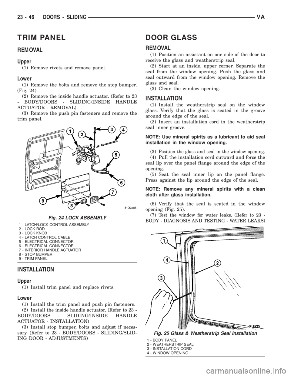
(1) Remove the bolts and remove the stop bumper.
(Fig. 24)
(2) Remove the inside handle actuator. (Refer to 23
- BODY/DOORS - SLIDING/INSIDE HANDLE
ACTUATOR - REMOVAL)
(3) Remove the push pin fasteners and remove the
trim panel.
INSTALLATION
Upper
(1) Install trim panel and replace rivets.
Lower
(1) Install the trim panel and push pin fasteners.
(2) Install the inside handle actuator. (Refer to 23 -
BODY/DOORS - SLIDING/INSIDE HANDLE
ACTUATOR - INSTALLATION)
(3) Install stop bumper, bolts and adjust if neces-
sary. (Refer to 23 - BODY/DOORS - SLIDING/SLID-
ING DOOR - ADJUSTMENTS)
DOOR GLASS
REMOVAL
(1) Position an assistant on one side of the door to
receive the glass and weatherstrip seal.
(2) Start at an inside, upper corner. Separate the
seal from the window opening. Push the glass and
seal outward from the window opening. Remove the
glass and seal.
(3) Clean the window opening.
INSTALLATION
(1) Install the weatherstrip seal on the window
glass. Verify that the glass is seated in the groove
around the edge of the seal.
(2) Insert an installation cord in the weatherstrip
seal inner groove.
NOTE: Use mineral spirits as a lubricant to aid seal
installation in the window opening.
(3)
Position the glass and seal in the window opening.
(4) Pull the installation cord outward and force the
seal lip over the panel flange around the edge of the
opening.
(5) Seat the seal inner lip on the panel flange.
Press against the lip around the edge of the seal.
NOTE: Remove any mineral spirits with a clean
cloth after glass installation.
(6) Verify that the seal is seated in the window
opening (Fig. 25).
(7)
Test the window for water leaks. (Refer to 23 -
BODY - DIAGNOSIS AND TESTING - WATER LEAKS)
Fig. 25 Glass & Weatherstrip Seal Installation
1 - BODY PANEL
2 - WEATHERSTRIP SEAL
3 - INSTALLATION CORD
4 - WINDOW OPENING
Fig. 24 LOCK ASSEMBLY
1 - LATCH/LOCK CONTROL ASSEMBLY
2 - LOCK ROD
3 - LOCK KNOB
4 - LATCH CONTROL CABLE
5 - ELECTRICAL CONNECTOR
6 - ELECTRICAL CONNECTOR
7 - INTERIOR HANDLE ACTUATOR
8 - STOP BUMPER
9 - TRIM PANEL
23 - 46 DOORS - SLIDINGVA
Page 1218 of 1232
HAT BRAKE - CLEANING, REAR DRUM
IN .................................5-27
HCU (HYDRAULIC CONTROL UNIT) -
DESCRIPTION........................5-31
HCU (HYDRAULIC CONTROL UNIT) -
INSTALLATION........................5-32
HCU (HYDRAULIC CONTROL UNIT) -
REMOVAL...........................5-31
HEAD - INSTALLATION, CYLINDER........9-25
HEAD - REMOVAL, CYLINDER...........9-22
HEAD BOLT INSPECTION - STANDARD
PROCEDURE, CYLINDER................9-21
HEAD COVER(S) - INSTALLATION,
CYLINDER...........................9-30
HEAD COVER(S) - REMOVAL, CYLINDER . . . 9-30
HEAD FRONT COVER - INSTALLATION,
CYLINDER...........................9-26
HEAD FRONT COVER - REMOVAL,
CYLINDER...........................9-23
HEAD GUIDE RAIL - INSTALLATION,
CYLINDER...........................9-26
HEAD GUIDE RAIL - REMOVAL,
CYLINDER...........................9-24
HEAD SURFACE - STANDARD
PROCEDURE, MEASURE CYLINDER.......9-21
HEADLAMP BULB - INSTALLATION, HIGH
BEAM..............................8L-17
HEADLAMP BULB - INSTALLATION, LOW
BEAM..............................8L-19
HEADLAMP BULB - REMOVAL, HIGH
BEAM..............................8L-17
HEADLAMP BULB - REMOVAL, LOW
BEAM...............................8L-18
HEADLAMP LEVELING MOTOR -
INSTALLATION.......................8L-16
HEADLAMP LEVELING MOTOR -
REMOVAL..........................8L-15
HEADLAMP LEVELING SWITCH -
INSTALLATION.......................8L-17
HEADLAMP LEVELING SWITCH -
REMOVAL..........................8L-16
HEADLINER - INSTALLATION...........23-71
HEADLINER - REMOVAL...............23-70
HEADREST - INSTALLATION............23-76
HEADREST - REMOVAL................23-76
HEATED SEAT ELEMENT - DESCRIPTION . . . 8G-3
HEATED SEAT ELEMENT - DIAGNOSIS
AND TESTING........................8G-3
HEATED SEAT ELEMENT - OPERATION.....8G-3
HEATED SEAT RELAY - DESCRIPTION.....8G-4
HEATED SEAT RELAY - DIAGNOSIS AND
TESTING............................8G-4
HEATED SEAT RELAY - INSTALLATION.....8G-4
HEATED SEAT RELAY - OPERATION.......8G-4
HEATED SEAT RELAY - REMOVAL........8G-4
HEATED SEAT SENSOR - DESCRIPTION....8G-4
HEATED SEAT SENSOR - DIAGNOSIS
AND TESTING........................8G-4
HEATED SEAT SWITCH - DESCRIPTION,
DRIVER.............................8G-2
HEATED SEAT SWITCH - DESCRIPTION,
PASSENGER.........................8G-5
HEATED SEAT SWITCH - DIAGNOSIS
AND TESTING, DRIVER.................8G-2
HEATED SEAT SWITCH - DIAGNOSIS
AND TESTING, PASSENGER.............8G-5
HEATED SEAT SWITCH - INSTALLATION,
DRIVER.............................8G-3
HEATED SEAT SWITCH - INSTALLATION,
PASSENGER.........................8G-5
HEATED SEAT SWITCH - OPERATION,
DRIVER.............................8G-2
HEATED SEAT SWITCH - OPERATION,
PASSENGER.........................8G-5
HEATED SEAT SWITCH - REMOVAL,
DRIVER.............................8G-3
HEATED SEAT SWITCH - REMOVAL,
PASSENGER.........................8G-5
HEATED SEATS - DESCRIPTION..........8G-1
HEATED SEATS - DIAGNOSIS AND
TESTING............................8G-2
HEATED SEATS - OPERATION
............8G-2
HEATER - DCHA - DIAGNOSIS AND
TESTING, DIESEL SUPPLEMENTAL
.......24-72
HEATER - DESCRIPTION, CABIN
.........24-72
HEATER - INSTALLATION, ENGINE
BLOCK
..............................7-14
HEATER - OPERATION, CABIN
...........24-72HEATER - REMOVAL, ENGINE BLOCK......7-14
HEATER AND AIR CONDITIONER -
DESCRIPTION........................24-1
HEATER AND AIR CONDITIONER -
OPERATION..........................24-2
HEATER CONTROL - DESCRIPTION, A/C . . . 24-12
HEATER CONTROL - INSTALLATION, A/C . . 24-13
HEATER CONTROL - OPERATION, A/C....24-12
HEATER CONTROL - REMOVAL, A/C......24-12
HEATER CORE - DESCRIPTION..........24-57
HEATER CORE - INSTALLATION.........24-58
HEATER CORE - OPERATION............24-57
HEATER CORE - REMOVAL.............24-58
HEATER PERFORMANCE - DIAGNOSIS
AND TESTING........................24-4
HI PRESSURE FUEL SHUTOFF SOL -
DESCRIPTION.......................14-16
HI PRESSURE FUEL SHUTOFF SOL -
OPERATION.........................14-16
HIGH BEAM HEADLAMP BULB -
INSTALLATION.......................8L-17
HIGH BEAM HEADLAMP BULB -
REMOVAL..........................8L-17
HIGH BEAM INDICATOR - DESCRIPTION . . 8J-17
HIGH BEAM INDICATOR - OPERATION....8J-17
HIGH FUEL SYSTEM PRESSURE -
WARNING...........................14-1
HIGH MOUNTED STOP LAMP BULB -
INSTALLATION, CENTER................8L-7
HIGH MOUNTED STOP LAMP BULB -
REMOVAL, CENTER....................8L-7
HIGH MOUNTED STOP LAMP UN -
INSTALLATION, CENTER................8L-8
HIGH MOUNTED STOP LAMP UN -
REMOVAL, CENTER....................8L-8
HIGH PRESSURE FUEL LINES -
DIAGNOSIS AND TESTING..............14-1
HIGH PRESSURE LINES - INSTALLATION . . . 14-7
HIGH PRESSURE LINES - REMOVAL......14-6
HIGH PRESSURE PUMP - DESCRIPTION . . . 14-7
HIGH PRESSURE PUMP - INSTALLATION . . 14-10
HIGH PRESSURE PUMP - REMOVAL......14-8
HIGH SPEEDS - DESCRIPTION, TIRE
PRESSURE..........................22-6
HINGE - INSTALLATION......23-17,23-34,23-50
HINGE - REMOVAL.........23-17,23-34,23-50
HITCH - INSTALLATION, TRAILER........13-10
HITCH - REMOVAL, TRAILER............13-9
HOAT COOLANT - DESCRIPTION..........0-2
HOISTING - STANDARD PROCEDURE.......0-5
HOLDDOWN - DESCRIPTION, BATTERY . . . 8F-14
HOLDDOWN - INSTALLATION, BATTERY . . . 8F-14
HOLDDOWN - REMOVAL, BATTERY......8F-14
HOLDER - INSTALLATION, CUP.........23-56
HOLDER - REMOVAL, CUP.............23-55
HOLDING CLUTCH B1 - ASSEMBLY.....21-113
HOLDING CLUTCH B1 - DISASSEMBLY . . 21-112
HOLDING CLUTCH B2 - ASSEMBLY.....21-116
HOLDING CLUTCH B2 - DISASSEMBLY . . 21-115
HOLDING CLUTCHES - DESCRIPTION....21-111
HOLDING CLUTCHES - OPERATION.....21-112
HOLE REPAIR - DESCRIPTION,
THREADED........................Intro.-5
HOOD - INSTALLATION................23-50
HOOD - REMOVAL....................23-50
HOOD BATTERY INSTALLATION,
INSTALLATION - UNDER...............8F-13
HOOD BATTERY REMOVAL, REMOVAL -
UNDER.............................8F-12
HORN - INSTALLATION.................8H-1
HORN - REMOVAL....................8H-1
HORN SWITCH - INSTALLATION
..........8H-1
HORN SWITCH - REMOVAL
.............8H-1
HOSE - INSTALLATION, INLET
..........24-78
HOSE - INSTALLATION, PRESSURE
......19-15
HOSE - REMOVAL, INLET
..............24-78
HOSE - REMOVAL, PRESSURE
..........19-15
HOSE FROM GEAR TO COOLER TUBE -
INSTALLATION, RETURN
...............19-15
HOSE FROM GEAR TO COOLER TUBE -
REMOVAL, RETURN
..................19-15
HOSES/LINES/TUBES PRECAUTIONS,
CAUTION - REFRIGERANT
..............24-45
HOSES/TUBES - DESCRIPTION, WASHER
. . 8R-8
HOSES/TUBES - OPERATION, WASHER
....8R-9
HOUSING - ASSEMBLY, HVAC
...........24-36
HOUSING - DISASSEMBLY, HVAC
........24-36HOUSING - INSTALLATION, AIR
CLEANER............................9-20
HOUSING - INSTALLATION, HVAC........24-36
HOUSING - INSTALLATION, REAR A/C....24-41
HOUSING - REMOVAL, AIR CLEANER......9-20
HOUSING - REMOVAL, HVAC...........24-34
HOUSING - REMOVAL, REAR A/C........24-40
HOW TO USE WIRING DIAGRAMS -
DESCRIPTION.....................8W-01-1
HUB / BEARING - INSTALLATION..........2-5
HUB / BEARING - REMOVAL..............2-4
HUB BEARINGS/SEALS - INSTALLATION,
AXLE...............................3-20
HUB BEARINGS/SEALS - REMOVAL,
AXLE...............................3-20
HUB SEAL - INSTALLATION, TORQUE
CONVERTER.......................21-147
HUB SEAL - REMOVAL, TORQUE
CONVERTER.......................21-147
HVAC HOUSING - ASSEMBLY...........24-36
HVAC HOUSING - DISASSEMBLY........24-36
HVAC HOUSING - INSTALLATION........24-36
HVAC HOUSING - REMOVAL............24-34
IDENTIFICATION - DESCRIPTION,
FASTENER.........................Intro.-2
IDENTIFICATION AND INFORMATION -
DESCRIPTION, SECTION.............8W-01-5
IDENTIFICATION NUMBER -
DESCRIPTION, VEHICLE..............Intro.-1
IGNITION CONTROL - SPECIAL TOOLS......8I-1
IGNITION-OFF DRAW TEST - STANDARD
PROCEDURE........................8F-10
INBOARD - INSTALLATION.............8O-30
INBOARD - REMOVAL.................8O-29
IN-CAR TEMPERATURE SENSOR -
DESCRIPTION.......................24-19
IN-CAR TEMPERATURE SENSOR -
DIAGNOSIS AND TESTING.............24-19
IN-CAR TEMPERATURE SENSOR -
OPERATION.........................24-19
IN-CAR TEMPERATURE SENSOR -
REMOVAL..........................24-19
INCORRECT FLUID LEVEL - DIAGNOSIS
AND TESTING, EFFECTS OF............21-102
INDICATOR - DESCRIPTION, ABS.........8J-9
INDICATOR - DESCRIPTION, AIRBAG.....8J-10
INDICATOR - DESCRIPTION, AMBIENT
TEMPERATURE......................8J-11
INDICATOR - DESCRIPTION, BRAKE
WEAR.............................8J-12
INDICATOR - DESCRIPTION, BRAKE/
PARK BRAKE........................8J-11
INDICATOR - DESCRIPTION, CHARGING . . . 8J-13
INDICATOR - DESCRIPTION, COOLANT
LOW...............................8J-14
INDICATOR - DESCRIPTION, FUEL
FILTER CLOGGED.....................8J-15
INDICATOR - DESCRIPTION, GEAR
SELECTOR..........................8J-17
INDICATOR - DESCRIPTION, HIGH BEAM . . 8J-17
INDICATOR - DESCRIPTION, LOW FUEL . . . 8J-18
INDICATOR - DESCRIPTION, LOW OIL
LEVEL.............................8J-18
INDICATOR - DESCRIPTION,
MAINTENANCE.......................8J-19
INDICATOR - DESCRIPTION, MULTI-
FUNCTION..........................8J-20
INDICATOR - DESCRIPTION, SEATBELT . . . 8J-22
INDICATOR - DESCRIPTION, TRACTION
CONTROL...........................8J-24
INDICATOR - DESCRIPTION, TRACTION
CONTROL MALFUNCTION..............8J-25
INDICATOR - DESCRIPTION, TURN
SIGNAL............................8J-25
INDICATOR - DESCRIPTION, WAIT-TO-
START .............................8J-26
INDICATOR - DESCRIPTION, WASHER
FLUID..............................8J-27
INDICATOR - DESCRIPTION, WATER-IN-
FUEL..............................8J-27
INDICATOR - OPERATION, ABS...........8J-9
INDICATOR - OPERATION, AIRBAG
.......8J-10
INDICATOR - OPERATION, AMBIENT
TEMPERATURE
......................8J-11
INDICATOR - OPERATION, BRAKE WEAR
. . 8J-12
INDICATOR - OPERATION, BRAKE/PARK
BRAKE
.............................8J-12
INDICATOR - OPERATION, CHARGING
....8J-13
8 INDEXVA
Description Group-Page Description Group-Page Description Group-Page
Page 1219 of 1232
INDICATOR - OPERATION, COOLANT
LOW...............................8J-14
INDICATOR - OPERATION, FUEL FILTER
CLOGGED...........................8J-15
INDICATOR - OPERATION, GEAR
SELECTOR..........................8J-17
INDICATOR - OPERATION, HIGH BEAM....8J-17
INDICATOR - OPERATION, LOW FUEL.....8J-18
INDICATOR - OPERATION, LOW OIL
LEVEL.............................8J-18
INDICATOR - OPERATION,
MAINTENANCE.......................8J-19
INDICATOR - OPERATION, MULTI-
FUNCTION..........................8J-21
INDICATOR - OPERATION, SEATBELT.....8J-22
INDICATOR - OPERATION, TRACTION
CONTROL...........................8J-24
INDICATOR - OPERATION, TRACTION
CONTROL MALFUNCTION..............8J-25
INDICATOR - OPERATION, TURN SIGNAL . . 8J-25
INDICATOR - OPERATION, WAIT-TO-
START .............................8J-26
INDICATOR - OPERATION, WASHER
FLUID..............................8J-27
INDICATOR - OPERATION, WATER-IN-
FUEL..............................8J-28
INDICATOR LAMP (MIL) - DESCRIPTION,
MALFUNCTION.......................8J-20
INDICATOR LAMP (MIL) - OPERATION,
MALFUNCTION.......................8J-20
INDICATORS - DIAGNOSIS AND
TESTING, TREAD WEAR................22-8
INFLATION PRESSURES - DESCRIPTION,
TIRE................................22-7
INITIAL OPERATION - STANDARD
PROCEDURE, POWER STEERING
PUMP.............................19-12
INJECTOR CLASSIFICATION - STANDARD
PROCEDURE........................14-22
INJECTOR, DESCRIPTION - FUEL........14-20
INJECTORS - STANDARD PROCEDURE,
CLEANING FUEL.....................14-22
INLET AIR TEMPERATURE SENSOR -
DESCRIPTION.......................14-29
INLET AIR TEMPERATURE SENSOR -
INSTALLATION.......................14-30
INLET AIR TEMPERATURE SENSOR -
OPERATION.........................14-29
INLET AIR TEMPERATURE SENSOR -
REMOVAL..........................14-30
INLET HOSE - INSTALLATION...........24-78
INLET HOSE - REMOVAL...............24-78
INNER BELT WEATHERSTRIP -
INSTALLATION, FRONT DOOR...........23-87
INNER BELT WEATHERSTRIP -
REMOVAL, FRONT DOOR..............23-87
INPUT SPEED SENSORS - DESCRIPTION . 21-119
INPUT SPEED SENSORS - OPERATION . . . 21-119
INSIDE HANDLE ACTUATOR -
INSTALLATION..................23-34,23-37
INSIDE HANDLE ACTUATOR -
REMOVAL.....................23-34,23-37
INSTRUMENT CLUSTER - DESCRIPTION . . . 8J-2
INSTRUMENT CLUSTER - DIAGNOSIS
AND TESTING........................8J-7
INSTRUMENT CLUSTER - INSTALLATION . . . 8J-9
INSTRUMENT CLUSTER - OPERATION.....8J-5
INSTRUMENT CLUSTER - REMOVAL......8J-7
INSTRUMENT PANEL - INSTALLATION....8L-29
INSTRUMENT PANEL - REMOVAL........8L-28
INSTRUMENT PANEL ANTENNA CABLE -
INSTALLATION.......................8A-2
INSTRUMENT PANEL ANTENNA CABLE -
REMOVAL...........................8A-1
INSTRUMENT PANEL ASSEMBLY -
INSTALLATION.......................23-61
INSTRUMENT PANEL ASSEMBLY -
REMOVAL..........................23-57
INSTRUMENT PANEL CENTER BEZEL -
INSTALLATION.......................23-55
INSTRUMENT PANEL CENTER BEZEL -
REMOVAL..........................23-55
INSTRUMENT PANEL DUCTS -
INSTALLATION
.......................24-38
INSTRUMENT PANEL DUCTS - REMOVAL
. 24-37
INTAKE MANIFOLD - INSTALLATION
.......9-58
INTAKE MANIFOLD - REMOVAL
..........9-57
INTERIOR - CAUTION
.................23-67INTERIOR - DESCRIPTION, LAMPS/
LIGHTING..........................8L-25
INTERIOR - OPERATION, LAMPS/
LIGHTING..........................8L-26
INTERIOR LIGHTING - SPECIFICATIONS . . . 8L-26
INTERMEDIATE GEAR - INSTALLATION.....9-66
INTERMEDIATE GEAR - REMOVAL........9-61
INTERMEDIATE SHAFT - INSTALLATION....19-5
INTERMEDIATE SHAFT - REMOVAL.......19-5
INTERNATIONAL SYMBOLS -
DESCRIPTION......................Intro.-2
INTERNATIONAL SYMBOLS -
DESCRIPTION.........................0-9
INTRUSION SENSOR - INSTALLATION.....8Q-2
INTRUSION SENSOR - REMOVAL.........8Q-2
INVERTED FLARING - STANDARD
PROCEDURE, DOUBLE..................5-8
ISO FLARING - STANDARD PROCEDURE....5-8
JAMB SWITCH - INSTALLATION, DOOR . . . 8L-31
JAMB SWITCH - REMOVAL, DOOR.......8L-31
JET - DESCRIPTION, OIL................9-51
JET - INSTALLATION, OIL...............9-51
JET - REMOVAL, OIL...................9-51
JOINT - INSTALLATION, LOWER BALL......2-6
JOINT - REMOVAL, LOWER BALL..........2-6
JOURNALS - STANDARD PROCEDURE,
MEASURE CRANKSHAFT AND BLOCK......9-35
JUMP STARTING - STANDARD
PROCEDURE............................0-6
K1 - ASSEMBLY, DRIVING CLUTCH.......21-75
K1 - DISASSEMBLY, DRIVING CLUTCH....21-74
K2 - ASSEMBLY, DRIVING CLUTCH.......21-78
K2 - DISASSEMBLY, DRIVING CLUTCH....21-76
K3 - ASSEMBLY, DRIVING CLUTCH.......21-80
K3 - DISASSEMBLY, DRIVING CLUTCH....21-80
KEY - DESCRIPTION, TRANSPONDER.....8Q-5
KEY - OPERATION, TRANSPONDER.......8Q-5
KEY REMOTE ENTRY MODULE -
DESCRIPTION, SENTRY................8Q-2
KEY REMOTE ENTRY MODULE -
INSTALLATION, SENTRY................8Q-4
KEY REMOTE ENTRY MODULE -
OPERATION, SENTRY..................8Q-3
KEY REMOTE ENTRY MODULE -
REMOVAL, SENTRY...................8Q-3
KEYLESS ENTRY TRANSMITTER -
DESCRIPTION, REMOTE................8N-2
KEY/LOCK CYLINDER - INSTALLATION.....19-7
KEY/LOCK CYLINDER - REMOVAL........19-6
KNUCKLE - INSTALLATION...............2-5
KNUCKLE - REMOVAL...................2-5
LAMP BULB - INSTALLATION, BACKUP....8L-6
LAMP BULB - INSTALLATION,
BRAKE/PARK.........................8L-7
LAMP BULB - INSTALLATION,
CARGO/DOME.......................8L-27
LAMP BULB - INSTALLATION, CENTER
HIGH MOUNTED STOP.................8L-7
LAMP BULB - INSTALLATION,
CLEARANCE..........................8L-8
LAMP BULB - INSTALLATION,
DOME/READING.....................8L-29
LAMP BULB - INSTALLATION,
ENTRY/EXIT.........................8L-32
LAMP BULB - INSTALLATION, FOG.......8L-10
LAMP BULB - INSTALLATION, FRONT
POSITION..........................8L-14
LAMP BULB - INSTALLATION, FRONT
TURN/PARK/SIDE MARKER.............8L-15
LAMP BULB - INSTALLATION, LICENSE
PLATE .............................8L-18
LAMP BULB - INSTALLATION, REAR
SIDE MARKER.......................8L-21
LAMP BULB - INSTALLATION, REAR
TURN..............................8L-22
LAMP BULB - INSTALLATION, REPEATER . . 8L-22
LAMP BULB - REMOVAL, BACKUP........8L-5
LAMP BULB - REMOVAL, BRAKE/PARK....8L-7
LAMP BULB - REMOVAL, CARGO/DOME . . 8L-27
LAMP BULB - REMOVAL, CENTER HIGH
MOUNTED STOP......................8L-7
LAMP BULB - REMOVAL, CLEARANCE
.....8L-8
LAMP BULB - REMOVAL, DOME/
READING
...........................8L-29
LAMP BULB - REMOVAL, ENTRY/EXIT
....8L-31
LAMP BULB - REMOVAL, FOG
..........8L-10
LAMP BULB - REMOVAL, FRONT
POSITION
..........................8L-14LAMP BULB - REMOVAL, FRONT
TURN/PARK/SIDE MARKER.............8L-14
LAMP BULB - REMOVAL, LICENSE
PLATE .............................8L-17
LAMP BULB - REMOVAL, REAR SIDE
MARKER...........................8L-21
LAMP BULB - REMOVAL, REAR TURN....8L-21
LAMP BULB - REMOVAL, REPEATER.....8L-22
LAMP (MIL) - DESCRIPTION,
MALFUNCTION INDICATOR.............8J-20
LAMP (MIL) - OPERATION,
MALFUNCTION INDICATOR.............8J-20
LAMP RELAY - INSTALLATION, DAYTIME
RUNNING............................8L-9
LAMP RELAY - INSTALLATION, FOG......8L-11
LAMP RELAY - REMOVAL, DAYTIME
RUNNING............................8L-9
LAMP RELAY - REMOVAL, FOG.........8L-10
LAMP SWITCH - INSTALLATION, BRAKE . . . 8L-6
LAMP SWITCH - INSTALLATION, FOG....8L-12
LAMP SWITCH - REMOVAL, BRAKE.......8L-6
LAMP SWITCH - REMOVAL, FOG........8L-11
LAMP UN - INSTALLATION, CENTER
HIGH MOUNTED STOP.................8L-8
LAMP UN - REMOVAL, CENTER HIGH
MOUNTED STOP......................8L-8
LAMP UNIT - ADJUSTMENT, FRONT......8L-12
LAMP UNIT - INSTALLATION, ASH
RECEIVER/CIGAR LIGHTER.............8L-27
LAMP UNIT - INSTALLATION, CARGO/
DOME...............................8L-28
LAMP UNIT - INSTALLATION,
CLEARANCE..........................8L-9
LAMP UNIT - INSTALLATION, DOME/
READING...........................8L-30
LAMP UNIT - INSTALLATION, ENTRY/
EXIT...............................8L-32
LAMP UNIT - INSTALLATION, FRONT.....8L-12
LAMP UNIT - INSTALLATION, LICENSE
PLATE .............................8L-18
LAMP UNIT - INSTALLATION, REPEATER . . 8L-23
LAMP UNIT - INSTALLATION, TAIL.......8L-23
LAMP UNIT - REMOVAL, ASH
RECEIVER/CIGAR LIGHTER.............8L-27
LAMP UNIT - REMOVAL, CARGO/DOME . . . 8L-28
LAMP UNIT - REMOVAL, CLEARANCE.....8L-8
LAMP UNIT - REMOVAL, DOME/
READING...........................8L-30
LAMP UNIT - REMOVAL, ENTRY/EXIT....8L-32
LAMP UNIT - REMOVAL, FRONT.........8L-12
LAMP UNIT - REMOVAL, LICENSE PLATE . . 8L-18
LAMP UNIT - REMOVAL, REPEATER......8L-22
LAMP UNIT - REMOVAL, TAIL...........8L-23
LAMP/INTRUSION SENSOR -
INSTALLATION, DOME.................8L-31
LAMP/INTRUSION SENSOR - REMOVAL,
DOME.............................8L-31
LAMP/INTRUSION SENSOR BULB -
INSTALLATION, DOME.................8L-30
LAMP/INTRUSION SENSOR BULB -
REMOVAL, DOME....................8L-30
LAMPS/LIGHTING - EXTERIOR -
DESCRIPTION........................8L-2
LAMPS/LIGHTING - EXTERIOR -
OPERATION..........................8L-3
LAMPS/LIGHTING - EXTERIOR -
SPECIFICATIONS......................8L-5
LAMPS/LIGHTING - INTERIOR -
DESCRIPTION.......................8L-25
LAMPS/LIGHTING - INTERIOR -
OPERATION.........................8L-26
LATCH - INSTALLATION.....23-18,23-35,23-51
LATCH - INSTALLATION, REAR..........23-40
LATCH - INSTALLATION, SAFETY........23-52
LATCH / LOCK CONTROL -
INSTALLATION.......................23-40
LATCH / LOCK CONTROL - REMOVAL.....23-39
LATCH - REMOVAL.........23-18,23-34,23-51
LATCH - REMOVAL, REAR..............23-40
LATCH - REMOVAL, SAFETY............23-52
LATCH RELEASE CABLE - INSTALLATION . . 23-51
LATCH RELEASE CABLE - REMOVAL.....23-51
LATCH RELEASE HANDLE -
INSTALLATION
.......................23-52
LATCH RELEASE HANDLE - REMOVAL
....23-52
LATCH STRIKER - INSTALLATION
........23-18
LATCH STRIKER - INSTALLATION, REAR
. . 23-41
LATCH STRIKER - REMOVAL
...........23-18
VAINDEX 9
Description Group-Page Description Group-Page Description Group-Page