2005 MERCEDES-BENZ SPRINTER width
[x] Cancel search: widthPage 101 of 1232
ACCESSORY DRIVE
TABLE OF CONTENTS
page page
BELT TENSIONERS
DESCRIPTION..........................5
OPERATION............................5
DRIVE BELTS
DIAGNOSIS AND TESTING - ACCESSORY
DRIVE BELT..........................5REMOVAL.............................8
INSTALLATION..........................8
BELT TENSIONERS
DESCRIPTION
CAUTION: Do not attempt to check belt tension with
a belt tension gauge on vehicles equipped with an
automatic belt tensioner.
Drive belts on all engines are equipped with a
spring loaded automatic belt tensioner. This ten-
sioner maintains constant belt tension at all times
and requires no maintenance or adjustment.
OPERATION
WARNING: THE AUTOMATIC BELT TENSIONER
ASSEMBLY IS SPRING LOADED. DO NOT ATTEMPT
TO DISASSEMBLE THE TENSIONER ASSEMBLY.
The automatic belt tensioner maintains correct belt
tension using a coiled spring within the tensioner
housing. The spring applies pressure to the tensioner
arm pressing the arm into the belt, tensioning the
belt.
If a new belt is being installed, the arrow must be
within approximately 3 mm (1/8 in.) of indexing
mark. Belt is considered new if it has been used 15
minutes or less. If this specification cannot be met,
check for:
²The wrong belt being installed (incorrect length/
width)
²Worn bearings on an engine accessory (A/C com-
pressor, power steering pump, water pump, idler pul-
ley or generator)
²A pulley on an engine accessory being loose
²Misalignment of an engine accessory
²Belt incorrectly routed.
DRIVE BELTS
DIAGNOSIS AND TESTING - ACCESSORY
DRIVE BELT
VISUAL DIAGNOSIS
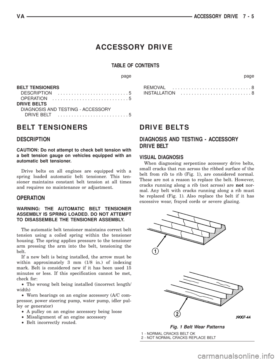
When diagnosing serpentine accessory drive belts,
small cracks that run across the ribbed surface of the
belt from rib to rib (Fig. 1), are considered normal.
These are not a reason to replace the belt. However,
cracks running along a rib (not across) arenotnor-
mal. Any belt with cracks running along a rib must
be replaced (Fig. 1). Also replace the belt if it has
excessive wear, frayed cords or severe glazing.
Fig. 1 Belt Wear Patterns
1 - NORMAL CRACKS BELT OK
2 - NOT NORMAL CRACKS REPLACE BELT
VAACCESSORY DRIVE 7 - 5
Page 173 of 1232
arate take out and connector of the vehicle wire
harness.
Located between the rear cover and the cluster
hood is the cluster housing. The molded plastic clus-
ter housing serves as the carrier for the cluster elec-
tronic circuit board and circuitry, the cluster
connector receptacles, the gauges, a Light Emitting
Diode (LED) for each cluster indicator and general
illumination lamp, the multi-function indicator LCD
unit, electronic tone generators, the cluster overlay,
the gauge pointers, the multi-function indicator
switches and the four switch push buttons.
The cluster overlay is a laminated plastic unit. The
dark, visible, outer surface of the overlay is marked
with all of the gauge dial faces and graduations, but
this layer is also translucent. The darkness of this
outer layer prevents the cluster from appearing clut-
tered or busy by concealing the cluster indicators
that are not illuminated, while the translucence of
this layer allows those indicators and icons that are
illuminated to be readily visible. The underlying
layer of the overlay is opaque and allows light from
the LED for each of the various indicators and illu-
mination lamps behind it to be visible through the
outer layer of the overlay only through predeter-
mined cutouts. A rectangular opening in the overlay
at the base of the speedometer provides a window
through which the illuminated multi-function indica-
tor LCD unit can be viewed.
Several versions of the EMIC module are offered
on this model. These versions accommodate all of the
variations of optional equipment and regulatory
requirements for the various markets in which the
vehicle will be offered. The microprocessor-based
EMIC utilizes integrated circuitry, Electrically Eras-
able Programmable Read Only Memory (EEPROM)
type memory storage, information carried on the
Controller Area Network (CAN) data bus, along with
several hard wired analog and multiplexed inputs to
monitor systems, sensors and switches throughout
the vehicle.
In response to those inputs, the hardware and soft-
ware of the EMIC allow it to control and integrate
many electronic functions and features of the vehicle
through both hard wired outputs and the transmis-
sion of electronic message outputs to other electronic
modules in the vehicle over the CAN data bus. (Refer
to 8 - ELECTRICAL/ELECTRONIC CONTROL
MODULES/COMMUNICATION - DESCRIPTION -
CAN BUS).
Besides typical instrument cluster gauge and indi-
cator support, the electronic functions and features
that the EMIC supports or controls include the fol-
lowing:
²Active Service System- In vehicles equipped
with the Active Service SYSTem (ASSYST) engine oilmaintenance indicator option, the EMIC electronic
circuit board includes a second dedicated micropro-
cessor. This second microprocessor evaluates various
data including time, mileage, and driving conditions
to calculate the required engine oil service intervals,
and provides both visual and audible alerts to the
vehicle operator when certain engine oil maintenance
services are required.
²Audible Warnings- The EMIC electronic cir-
cuit board is equipped with an audible tone generator
and programming that allows it to provide various
audible alerts to the vehicle operator, including buzz-
ing and chime tones. An audible contactless elec-
tronic relay is also soldered onto the circuit board to
produce audible clicks that is synchronized with turn
signal indicator flashing to emulate the sounds of a
conventional turn signal or hazard warning flasher.
These audible clicks can occur at one of two rates to
emulate both normal and bulb-out turn or hazard
flasher operation. (Refer to 8 - ELECTRICAL/
CHIME/BUZZER - DESCRIPTION).
²Panel Lamps Dimming Control- The EMIC
provides a hard wired 12-volt Pulse-Width Modulated
(PWM) output that synchronizes the dimming level
of all panel lamps dimmer controlled lamps with that
of the cluster general illumination lamps and multi-
function indicator.
The EMIC houses four analog gauges and has pro-
visions for up to nineteen indicators (Fig. 3). The
EMIC includes the following analog gauges:
²Coolant Temperature Gauge
²Fuel Gauge
²Speedometer
²Tachometer
The EMIC includes provisions for the following
indicators (Fig. 3):
²Airbag (SRS) Indicator
²Antilock Brake System (ABS) Indicator
²Brake Indicator
²Brake Wear Indicator
²Charging Indicator
²Clogged Fuel Filter Indicator
²Coolant Low Indicator
²High Beam Indicator
²Low Fuel Indicator
²Malfunction Indicator Lamp (MIL)
²Multi-Function Indicator (LCD)
²Seatbelt Indicator
²Traction Control (ASR) Indicator
²Traction Control (ASR) Malfunction Indica-
tor
²Turn Signal (Right and Left) Indicators
²Washer Fluid Indicator
²Wait-To-Start Indicator
²Water-In-Fuel Indicator
VAINSTRUMENT CLUSTER 8J - 3
INSTRUMENT CLUSTER (Continued)
Page 176 of 1232
INDICATORS
Indicators are located in various positions within
the EMIC and are all connected to the EMIC elec-
tronic circuit board. The ambient temperature indica-
tor (optional), brake indicator, brake wear indicator,
charging indicator, coolant low indicator, high beam
indicator, low fuel indicator, seatbelt indicator, turn
signal indicators, and washer fluid indicator operate
based upon hard wired inputs to the EMIC. The air-
bag (SRS) indicator is normally controlled by a hard
wired input from the Airbag Control Module (ACM);
however, if the EMIC sees an abnormal or no input
from the ACM, it will automatically turn the airbag
indicator On until the hard wired input from the
ACM has been restored. The Malfunction Indicator
Lamp (MIL) is normally controlled by CAN data bus
messages from the Engine Control Module (ECM);
however, if the EMIC loses CAN data bus communi-
cation, the EMIC circuitry will automatically turn
the MIL on until CAN data bus communication is
restored. The EMIC uses CAN data bus messages
from the ECM, the ACM, and the Controller Antilock
Brake to control all of the remaining indicators.
The various EMIC indicators are controlled by dif-
ferent strategies; some receive battery feed from the
EMIC circuitry and have a switched ground, while
others are grounded through the EMIC circuitry and
have a switched battery feed. However, all indicators
are completely controlled by the EMIC microproces-
sor based upon various hard wired and electronic
message inputs. Except for the indications provided
by the multi-function indicator Liquid Crystal Dis-
play (LCD) unit, all indicators are illuminated at a
fixed intensity, which is not affected by the selected
illumination intensity of the EMIC general illumina-
tion lamps.
The hard wired indicator inputs may be diagnosed
using conventional diagnostic methods. However,
proper testing of the EMIC circuitry and the CAN
bus message controlled indicators requires the use of
a DRBIIItscan tool. Refer to the appropriate diag-
nostic information. Specific details of the operation
for each indicator may be found elsewhere in this
service information.
CLUSTER ILLUMINATION
The EMIC has several general illumination lamps
that are illuminated when the exterior lighting is
turned on with the multi-function switch. The illumi-
nation intensity of these lamps is adjusted by a dim-
ming level input received from the multi-function
indicator ª+º (plus) and ª±º (minus) switch push but-
tons that extend through the lower edge of the clus-
ter lens below the right end of the multi-function
indicator. When the exterior lighting is turned Off,
the display is illuminated at maximum brightness.When the exterior lighting is turned On and the
transmission gear selector is in the Park position,
depressing the plus switch push button brightens the
display lighting, and depressing the minus switch
push button dims the display lighting. The EMIC
also provides a Pulse-Width Modulated (PWM) panel
lamps dimmer output that can be used to synchro-
nize the illumination lighting levels of external illu-
mination lamps (up to about 23 to 30 watts) with
that of the EMIC.
The hard wired multi-function switch input and
the EMIC panel lamps dimmer output may be diag-
nosed using conventional diagnostic methods. How-
ever, proper testing of the PWM control of the EMIC
and the electronic dimming level inputs from the
multi-function indicator push buttons requires the
use of a DRBIIItscan tool. Refer to the appropriate
diagnostic information.
INPUT AND OUTPUT CIRCUITS
HARD WIRED INPUTS
The hard wired inputs to the EMIC include the fol-
lowing:
NOTE: Final approved circuit names were not yet
available at the time this information was compiled.
²Airbag Indicator Driver
²Ambient Temperature Sensor Signal
(Optional)
²Brake Wear Indicator Sense
²Charging Indicator Driver
²Coolant Level Switch Sense
²Front Door Jamb Switch Sense
²Fuel Level Sensor Signal
²Fused B(+)
²Fused Ignition Switch Output
²High Beam Indicator Driver
²Key-In Ignition Switch Sense
²Left Turn Signal
²Park Brake Switch Sense
²Right Turn Signal
²Seat Belt Switch Sense
²Washer Fluid Switch Sense (Optional)
Refer to the appropriate wiring information for
additional details.
HARD WIRED OUTPUTS
The hard wired outputs of the EMIC include the
following:
NOTE: Final approved circuit names were not yet
available at the time this information was compiled.
²Engine Running Relay Control
²Panel Lamps Driver
8J - 6 INSTRUMENT CLUSTERVA
INSTRUMENT CLUSTER (Continued)
Page 780 of 1232
CONNECTING ROD SPECIFICATIONS
Distance between middle
connecting rod bore to
connecting rod bushing
bore148.970 mm to 149.030
mm
Width of connecting rod
bearing bore at
connecting rod bushing
bore21.940 mm to 22 mm
Connecting rod bearing
shell basic bore51.600 mm to 51.614
mm
Allowable out-of-
roundness and taper of
basic bore.020 mm
Allowable twist of
connecting rod bearing
bore to connecting rod
bushing bore over a
length of 100 mm.100 mm
Allowable variation of
axial parallelism of
connecting rod bearing
bore to connecting rod
bushing bore over a
length of 100 mm.045 mm
Allowable difference in
weight of complete
connecting rod of an
engine2g
Connecting rod inner
bushing30.018 to 30.024 mm
Connecting rod outer
bushing32.575 mm to 32.600
mm
Connecting rod basic
bore32.500 mm to 32.525
mm
Piston pin play in
connecting rod.018 mm to .024 mm
Peak-to-Valley height
(Rz) of connecting rod
bushing on inside5
Connecting rod bolt
threadM8x1
STANDARD PROCEDURE - MEASURING
PISTON PROTRUSION
After replacing the pistons/connecting rods or
machining the engine block contact surface, it is then
necessary to measure the piston protrusion.
Measure protrusion between piston crown and cyl-
inder head contact surface without the head gasket
installed. The measurment must be carried out inthe direction of the piston pin in order to eliminate
piston rock.
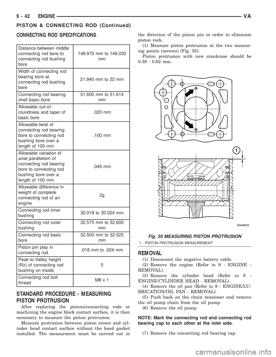
(1) Measure piston protrusion at the two measur-
ing points (arrows) (Fig. 35).
Piston protrusion with new crankcase should be
0.38 - 0.62 mm.
REMOVAL
(1) Disconnect the negative battery cable.
(2) Remove the engine (Refer to 9 - ENGINE -
REMOVAL).
(3) Remove the cylinder head (Refer to 9 -
ENGINE/CYLINDER HEAD - REMOVAL).
(4) Remove the oil pan (Refer to 9 - ENGINE/LU-
BRICATION/OIL PAN - REMOVAL).
(5) Push back on the chain tensioner and remove
the oil pump chain from the oil pump.
(6) Remove the oil pump.
NOTE: Mark the connecting rod and connecting rod
bearing cap to each other at the inlet side.
(7) Remove the connecting rod bearing cap.
Fig. 35 MEASURING PISTON PROTRUSION
1 - PISTON PROTRUSION MEASUREMENT
9 - 42 ENGINEVA
PISTON & CONNECTING ROD (Continued)
Page 1012 of 1232
SOLENOID
DESCRIPTION
The typical electrical solenoid used in automotive
applications is a linear actuator. It is a device that
produces motion in a straight line. This straight line
motion can be either forward or backward in direc-
tion, and short or long distance.
A solenoid is an electromechanical device that uses
a magnetic force to perform work. It consists of a coil
of wire, wrapped around a magnetic core made from
steel or iron, and a spring loaded, movable plunger,
which performs the work, or straight line motion.
The solenoids used in transmission applications
are attached to valves which can be classified asnor-
mally openornormally closed. Thenormally
opensolenoid valve is defined as a valve which
allows hydraulic flow when no current or voltage is
applied to the solenoid. Thenormally closedsole-
noid valve is defined as a valve which does not allow
hydraulic flow when no current or voltage is applied
to the solenoid. These valves perform hydraulic con-
trol functions for the transmission and must there-
fore be durable and tolerant of dirt particles. For
these reasons, the valves have hardened steel pop-
pets and ball valves. The solenoids operate the valves
directly, which means that the solenoids must have
very high outputs to close the valves against the siz-
able flow areas and line pressures found in current
transmissions. Fast response time is also necessary
to ensure accurate control of the transmission.
The strength of the magnetic field is the primary
force that determines the speed of operation in a par-
ticular solenoid design. A stronger magnetic field will
cause the plunger to move at a greater speed than a
weaker one. There are basically two ways to increase
the force of the magnetic field:
1. Increase the amount of current applied to the
coil or
2. Increase the number of turns of wire in the coil.
The most common practice is to increase the num-
ber of turns by using thin wire that can completely
fill the available space within the solenoid housing.
The strength of the spring and the length of the
plunger also contribute to the response speed possi-
ble by a particular solenoid design.
A solenoid can also be described by the method by
which it is controlled. Some of the possibilities
include variable force, pulse-width modulated, con-
stant ON, or duty cycle. The variable force and pulse-
width modulated versions utilize similar methods to
control the current flow through the solenoid to posi-
tion the solenoid plunger at a desired position some-
where between full ON and full OFF. The constant
ON and duty cycled versions control the voltage
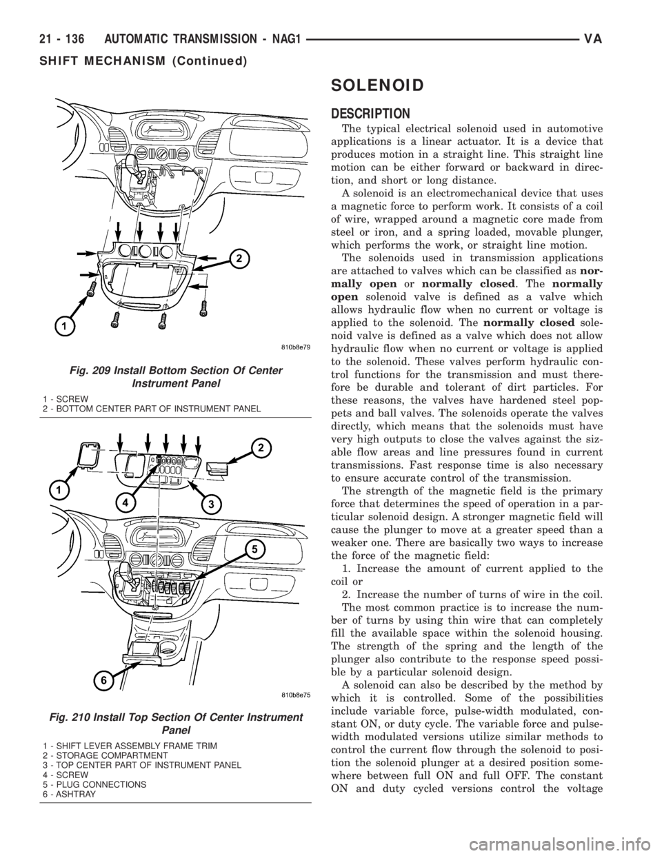
Fig. 209 Install Bottom Section Of Center
Instrument Panel
1 - SCREW
2 - BOTTOM CENTER PART OF INSTRUMENT PANEL
Fig. 210 Install Top Section Of Center Instrument
Panel
1 - SHIFT LEVER ASSEMBLY FRAME TRIM
2 - STORAGE COMPARTMENT
3 - TOP CENTER PART OF INSTRUMENT PANEL
4 - SCREW
5 - PLUG CONNECTIONS
6 - ASHTRAY
21 - 136 AUTOMATIC TRANSMISSION - NAG1VA
SHIFT MECHANISM (Continued)
Page 1035 of 1232
WHEELS
DESCRIPTION
Original equipment wheels are designed for the
specified Maximum Vehicle Capacity.
All models use steel or aluminum wheels.
Aluminum wheels require special balance weights
and alignment equipment.
(1) On vehicles equipped with dual rear wheels,
The slots in the wheel must be aligned to provide
access to the valve stem.
OPERATION
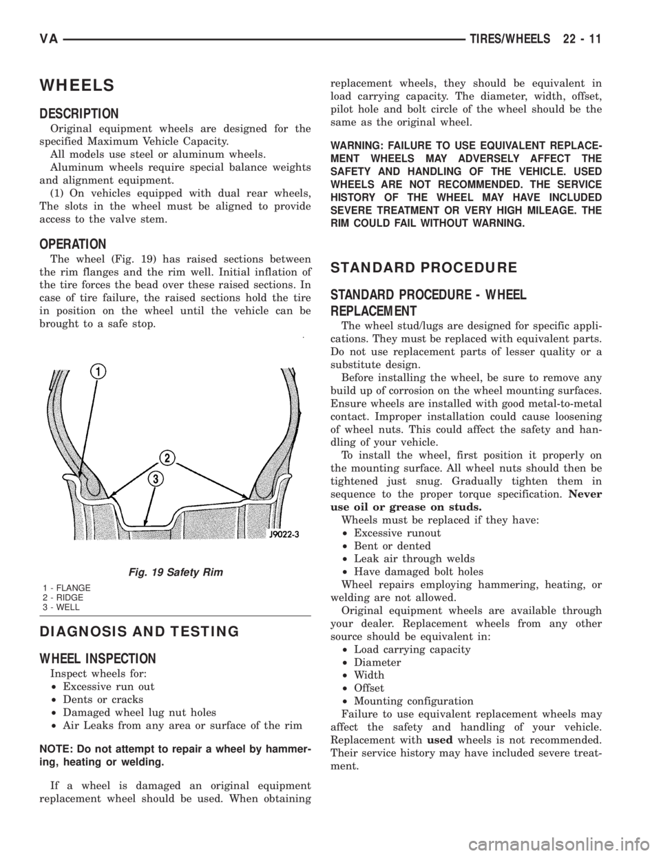
The wheel (Fig. 19) has raised sections between
the rim flanges and the rim well. Initial inflation of
the tire forces the bead over these raised sections. In
case of tire failure, the raised sections hold the tire
in position on the wheel until the vehicle can be
brought to a safe stop.
DIAGNOSIS AND TESTING
WHEEL INSPECTION
Inspect wheels for:
²Excessive run out
²Dents or cracks
²Damaged wheel lug nut holes
²Air Leaks from any area or surface of the rim
NOTE: Do not attempt to repair a wheel by hammer-
ing, heating or welding.
If a wheel is damaged an original equipment
replacement wheel should be used. When obtainingreplacement wheels, they should be equivalent in
load carrying capacity. The diameter, width, offset,
pilot hole and bolt circle of the wheel should be the
same as the original wheel.
WARNING: FAILURE TO USE EQUIVALENT REPLACE-
MENT WHEELS MAY ADVERSELY AFFECT THE
SAFETY AND HANDLING OF THE VEHICLE. USED
WHEELS ARE NOT RECOMMENDED. THE SERVICE
HISTORY OF THE WHEEL MAY HAVE INCLUDED
SEVERE TREATMENT OR VERY HIGH MILEAGE. THE
RIM COULD FAIL WITHOUT WARNING.
STANDARD PROCEDURE
STANDARD PROCEDURE - WHEEL
REPLACEMENT
The wheel stud/lugs are designed for specific appli-
cations. They must be replaced with equivalent parts.
Do not use replacement parts of lesser quality or a
substitute design.
Before installing the wheel, be sure to remove any
build up of corrosion on the wheel mounting surfaces.
Ensure wheels are installed with good metal-to-metal
contact. Improper installation could cause loosening
of wheel nuts. This could affect the safety and han-
dling of your vehicle.
To install the wheel, first position it properly on
the mounting surface. All wheel nuts should then be
tightened just snug. Gradually tighten them in
sequence to the proper torque specification.Never
use oil or grease on studs.
Wheels must be replaced if they have:
²Excessive runout
²Bent or dented
²Leak air through welds
²Have damaged bolt holes
Wheel repairs employing hammering, heating, or
welding are not allowed.
Original equipment wheels are available through
your dealer. Replacement wheels from any other
source should be equivalent in:
²Load carrying capacity
²Diameter
²Width
²Offset
²Mounting configuration
Failure to use equivalent replacement wheels may
affect the safety and handling of your vehicle.
Replacement withusedwheels is not recommended.
Their service history may have included severe treat-
ment.
Fig. 19 Safety Rim
1 - FLANGE
2 - RIDGE
3 - WELL
VATIRES/WHEELS 22 - 11
Page 1046 of 1232
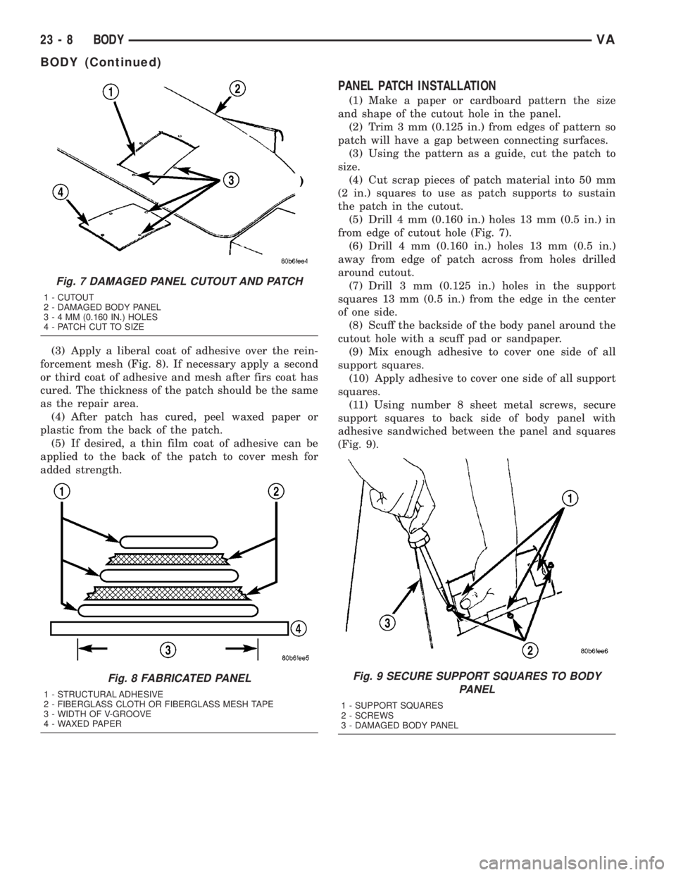
(3) Apply a liberal coat of adhesive over the rein-
forcement mesh (Fig. 8). If necessary apply a second
or third coat of adhesive and mesh after firs coat has
cured. The thickness of the patch should be the same
as the repair area.
(4) After patch has cured, peel waxed paper or
plastic from the back of the patch.
(5) If desired, a thin film coat of adhesive can be
applied to the back of the patch to cover mesh for
added strength.
PANEL PATCH INSTALLATION
(1) Make a paper or cardboard pattern the size
and shape of the cutout hole in the panel.
(2) Trim 3 mm (0.125 in.) from edges of pattern so
patch will have a gap between connecting surfaces.
(3) Using the pattern as a guide, cut the patch to
size.
(4) Cut scrap pieces of patch material into 50 mm
(2 in.) squares to use as patch supports to sustain
the patch in the cutout.
(5) Drill 4 mm (0.160 in.) holes 13 mm (0.5 in.) in
from edge of cutout hole (Fig. 7).
(6) Drill 4 mm (0.160 in.) holes 13 mm (0.5 in.)
away from edge of patch across from holes drilled
around cutout.
(7) Drill 3 mm (0.125 in.) holes in the support
squares 13 mm (0.5 in.) from the edge in the center
of one side.
(8) Scuff the backside of the body panel around the
cutout hole with a scuff pad or sandpaper.
(9) Mix enough adhesive to cover one side of all
support squares.
(10) Apply adhesive to cover one side of all support
squares.
(11) Using number 8 sheet metal screws, secure
support squares to back side of body panel with
adhesive sandwiched between the panel and squares
(Fig. 9).
Fig. 7 DAMAGED PANEL CUTOUT AND PATCH
1 - CUTOUT
2 - DAMAGED BODY PANEL
3-4MM(0.160 IN.) HOLES
4 - PATCH CUT TO SIZE
Fig. 8 FABRICATED PANEL
1 - STRUCTURAL ADHESIVE
2 - FIBERGLASS CLOTH OR FIBERGLASS MESH TAPE
3 - WIDTH OF V-GROOVE
4 - WAXED PAPER
Fig. 9 SECURE SUPPORT SQUARES TO BODY
PANEL
1 - SUPPORT SQUARES
2 - SCREWS
3 - DAMAGED BODY PANEL
23 - 8 BODYVA
BODY (Continued)