2005 MERCEDES-BENZ SPRINTER flat tire
[x] Cancel search: flat tirePage 29 of 1232
(7) Insert the shear bushing and retaining bolt
into the hole and tighten to 130 N´m (96 ft.lbs.).
(8) Remove the jack and lower the vehicle.
SPRING STOP PLATES
REMOVAL
(1) Raise and support the vehicle.
(2) Remove the tire and wheel assembly.
(3) Remove the lower end of the stabilizer link
from the stop plate.
(4) Remove the three bolts retaining the spring
stop plate from the lower control arm.
INSTALLATION
(1) Install the spring stop plate to the lower con-
trol arm. Tighten the bolts to 60 N´m (44 ft. lbs.).
(2) Install the stabilizer link to the spring stop
plate.
(3) Install the tire and wheel assembly.
(4) Lower the vehicle.
STABILIZER BAR
DESCRIPTION
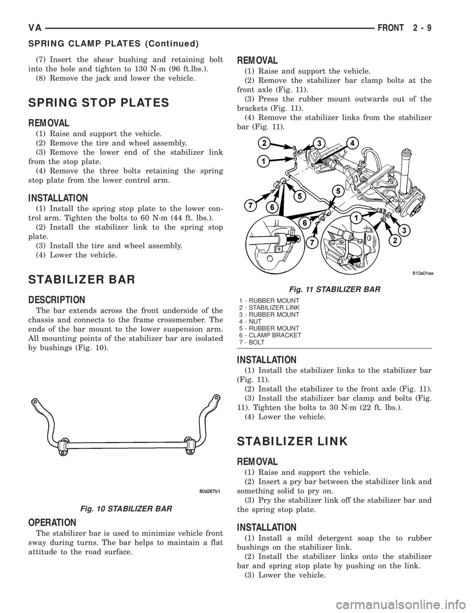
The bar extends across the front underside of the
chassis and connects to the frame crossmember. The
ends of the bar mount to the lower suspension arm.
All mounting points of the stabilizer bar are isolated
by bushings (Fig. 10).
OPERATION
The stabilizer bar is used to minimize vehicle front
sway during turns. The bar helps to maintain a flat
attitude to the road surface.
REMOVAL
(1) Raise and support the vehicle.
(2) Remove the stabilizer bar clamp bolts at the
front axle (Fig. 11).
(3) Press the rubber mount outwards out of the
brackets (Fig. 11).
(4) Remove the stabilizer links from the stabilizer
bar (Fig. 11).
INSTALLATION
(1) Install the stabilizer links to the stabilizer bar
(Fig. 11).
(2) Install the stabilizer to the front axle (Fig. 11).
(3) Install the stabilizer bar clamp and bolts (Fig.
11). Tighten the bolts to 30 N´m (22 ft. lbs.).
(4) Lower the vehicle.
STABILIZER LINK
REMOVAL
(1) Raise and support the vehicle.
(2) Insert a pry bar between the stabilizer link and
something solid to pry on.
(3) Pry the stabilizer link off the stabilizer bar and
the spring stop plate.
INSTALLATION
(1) Install a mild detergent soap the to rubber
bushings on the stabilizer link.
(2) Install the stabilizer links onto the stabilizer
bar and spring stop plate by pushing on the link.
(3) Lower the vehicle.
Fig. 10 STABILIZER BAR
Fig. 11 STABILIZER BAR
1 - RUBBER MOUNT
2 - STABILIZER LINK
3 - RUBBER MOUNT
4 - NUT
5 - RUBBER MOUNT
6 - CLAMP BRACKET
7 - BOLT
VAFRONT 2 - 9
SPRING CLAMP PLATES (Continued)
Page 43 of 1232
(15) If vibration remains unacceptable, preform
the procedure to the front end of the propeller shaft.
(16) Install the wheel and tires. Lower the vehicle.
PROPELLER SHAFT RUNOUT
(1) Clean the propeller shaft surface where the
dial indicator will contact the shaft.
(2) The dial indicator must be installed perpendic-
ular to the shaft surface.
(3) Measure runout at the center and ends of the
shaft away from weld areas, to ensure weld process
will not effect the measurements.
(4) Refer to Runout Specifications chart.
(5) If propeller shaft is out of specification, remove
propeller shaft and index the shaft 180É. Install the
propeller shaft and measure shaft runout again.
(6) If propeller shaft is now within specifications,
mark shaft and yokes for proper orientation.
(7) If propeller shaft runout is not within specifica-
tions, check runout of the transmission and axle.
Correct as necessary and repeat propeller shaft
runout measurement.
(8) Replace propeller shaft if the runout still
exceeds the limits.
RUNOUT SPECIFICATIONS
Front of Shaft 0.020 in. (0.50 mm)
Center of Shaft 0.025 in. (0.63 mm)
Rear of Shaft 0.020 in. (0.50 mm)
note:
Measure front/rear runout approximately 76 mm (3 in.)
from the weld seam at each end of the shaft tube for
tube lengths over 30 inches. For tube lengths under
30 inches, the maximum allowed runout is 0.50 mm
(0.020 in.) for the full length of the tube.
STANDARD PROCEDURE
PROPELLER SHAFT ANGLE
This procedure applies the front and rear propeller
shafts.
(1) Place vehicle in netural.
(2) Raise and support vehicle at the axles as level
as possible.
(3) Remove universal joint snap rings if equipped,
so Inclinometer 7663 base sits flat.
(4) Rotate shaft until transmission case output
yoke bearing is facing downward.
NOTE: Always make measurements from front to
rear and from the same side of the vehicle.
(5) Place Inclinometer 7663 on yoke bearing (A)
parallel to the shaft. Center bubble in sight glass and
record measurement.
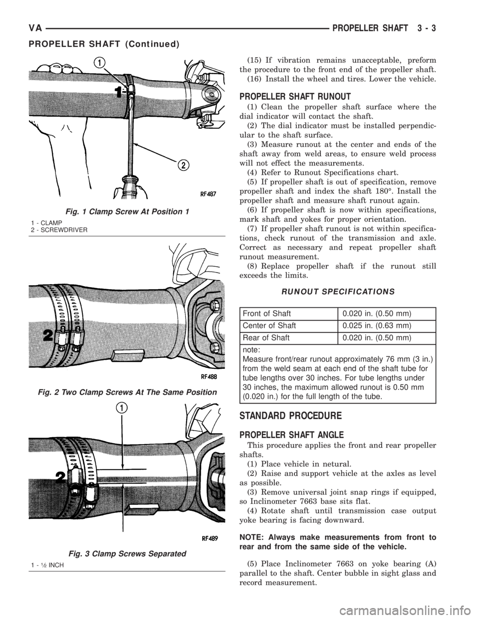
Fig. 1 Clamp Screw At Position 1
1 - CLAMP
2 - SCREWDRIVER
Fig. 2 Two Clamp Screws At The Same Position
Fig. 3 Clamp Screws Separated
1-1¤2INCH
VAPROPELLER SHAFT 3 - 3
PROPELLER SHAFT (Continued)
Page 66 of 1232
STANDARD PROCEDURE - MASTER
CYLINDER BLEEDING..................17
REMOVAL.............................17
INSTALLATION.........................18
PEDAL
REMOVAL.............................18
INSTALLATION.........................19
POWER BRAKE BOOSTER
DESCRIPTION.........................19
OPERATION...........................19
REMOVAL.............................19
INSTALLATION.........................19
ROTORS
REMOVAL
REMOVAL - FRONT (SRW)..............19
REMOVAL - REAR (SRW)...............20
REMOVAL - FRONT (DRW)..............20
REMOVAL - REAR (DRW)...............20
INSTALLATION
INSTALLATION - FRONT (SRW)..........21
INSTALLATION - REAR (SRW)...........21
INSTALLATION - FRONT (DRW)..........21
INSTALLATION - REAR (DRW)...........21
SUPPORT PLATE
REMOVAL - REAR......................22
INSTALLATION - REAR...................22
PARKING BRAKE
SPECIFICATIONS
TORQUE CHART......................22SPECIAL TOOLS
PARK BRAKE........................23
CABLE TENSIONER
REMOVAL.............................23
INSTALLATION.........................23
CABLES
REMOVAL
REMOVAL - FRONT....................24
REMOVAL - REAR.....................24
INSTALLATION
INSTALLATION - FRONT................24
INSTALLATION - REAR.................25
ADJUSTMENTS
ADJUSTMENT - PARKING BRAKE CABLES . 25
LEVER
REMOVAL.............................26
INSTALLATION.........................26
SHOES
REMOVAL
REMOVAL - (SRW)....................26
REMOVAL - (DRW)....................26
CLEANING - REAR DRUM IN HAT BRAKE....27
INSTALLATION
INSTALLATION - (SRW).................27
INSTALLATION - (DRW).................27
ADJUSTMENTS
ADJUSTMENT........................27
BRAKES - BASE
DIAGNOSIS AND TESTING - BASE BRAKE
SYSTEM
Base brake components consist of the brake pads,
calipers, brake drum in hat rotor in the rear, rotors,
brake lines, master cylinder, booster, and parking
brake components.
Brake diagnosis involves determining if the prob-
lem is related to a mechanical, hydraulic, or vacuum
operated component.
The first diagnosis step is the preliminary check.
PRELIMINARY BRAKE CHECK
(1) Check condition of tires and wheels. Damaged
wheels and worn, damaged, or underinflated tires
can cause pull, shudder, vibration, and a condition
similar to grab.
(2) If complaint was based on noise when braking,
check suspension components. Jounce front and rear
of vehicle and listen for noise that might be caused
by loose, worn or damaged suspension or steering
components.(3) Inspect brake fluid level and condition. Note
that the brake reservoir fluid level will decrease in
proportion to normal lining wear.Also note that
brake fluid tends to darken over time. This is
normal and should not be mistaken for contam-
ination.
(a) If fluid level is abnormally low, look for evi-
dence of leaks at calipers, wheel cylinders, brake
lines, and master cylinder.
(b) If fluid appears contaminated, drain out a
sample to examine. System will have to be flushed
if fluid is separated into layers, or contains a sub-
stance other than brake fluid. The system seals
and cups will also have to be replaced after flush-
ing. Use clean brake fluid to flush the system.
(4) Check parking brake operation. Verify free
movement and full release of cables and pedal. Also
note if vehicle was being operated with parking
brake partially applied.
(5) Check brake pedal operation. Verify that pedal
does not bind and has adequate free play. If pedal
lacks free play, check pedal and power booster for
being loose or for bind condition. Do not road test
until condition is corrected.
(6) Check booster vacuum check valve and hose.
(7) If components checked appear OK, road test
the vehicle.
5 - 2 BRAKES - BASEVA
Page 68 of 1232
A worn, damaged wheel bearing or suspension
component are further causes of pull. A damaged
front tire (bruised, ply separation) can also cause
pull.
A common and frequently misdiagnosed pull condi-
tion is where direction of pull changes after a few
stops. The cause is a combination of brake drag fol-
lowed by fade at one of the brake units.
As the dragging brake overheats, efficiency is so
reduced that fade occurs. Since the opposite brake
unit is still functioning normally, its braking effect is
magnified. This causes pull to switch direction in
favor of the normally functioning brake unit.
An additional point when diagnosing a change in
pull condition concerns brake cool down. Remember
that pull will return to the original direction, if the
dragging brake unit is allowed to cool down (and is
not seriously damaged).
REAR BRAKE GRAB OR PULL
Rear grab or pull is usually caused by improperly
adjusted or seized parking brake cables, contami-
nated lining, bent or binding shoes and support
plates, or improperly assembled components. This is
particularly true when only one rear wheel is
involved. However, when both rear wheels are
affected, the master cylinder or proportioning valve
could be at fault.
BRAKES DO NOT HOLD AFTER DRIVING THROUGH DEEP
WATER PUDDLES
This condition is generally caused by water soaked
lining. If the lining is only wet, it can be dried by
driving with the brakes very lightly applied for a
mile or two. However, if the lining is both soaked and
dirt contaminated, cleaning and/or replacement will
be necessary.
BRAKE LINING CONTAMINATION
Brake lining contamination is mostly a product of
leaking calipers or worn seals, driving through deep
water puddles, or lining that has become covered
with grease and grit during repair. Contaminated lin-
ing should be replaced to avoid further brake prob-
lems.
WHEEL AND TIRE PROBLEMS
Some conditions attributed to brake components
may actually be caused by a wheel or tire problem.
A damaged wheel can cause shudder, vibration and
pull. A worn or damaged tire can also cause pull.
Severely worn tires with very little tread left can
produce a grab-like condition as the tire loses and
recovers traction. Flat-spotted tires can cause vibra-
tion and generate shudder during brake operation. A
tire with internal damage such as a severe bruise,
cut, or ply separation can cause pull and vibration.BRAKE NOISES
Some brake noise is common with rear drum
brakes and on some disc brakes during the first few
stops after a vehicle has been parked overnight or
stored. This is primarily due to the formation of trace
corrosion (light rust) on metal surfaces. This light
corrosion is typically cleared from the metal surfaces
after a few brake applications causing the noise to
subside.
BRAKE SQUEAK/SQUEAL
Brake squeak or squeal may be due to linings that
are wet or contaminated with brake fluid, grease, or
oil. Glazed linings and rotors with hard spots can
also contribute to squeak. Dirt and foreign material
embedded in the brake lining will also cause squeak/
squeal.
A very loud squeak or squeal is frequently a sign of
severely worn brake lining. If the lining has worn
through to the brake pads in spots, metal-to-metal
contact occurs. If the condition is allowed to continue,
rotors can become so scored that replacement is nec-
essary.
BRAKE CHATTER
Brake chatter is usually caused by loose or worn
components, or glazed/burnt lining. Rotors with hard
spots can also contribute to chatter. Additional causes
of chatter are out-of-tolerance rotors, brake lining not
securely attached to the shoes, loose wheel bearings
and contaminated brake lining.
THUMP/CLUNK NOISE
Thumping or clunk noises during braking are fre-
quentlynotcaused by brake components. In many
cases, such noises are caused by loose or damaged
steering, suspension, or engine components. However,
calipers that bind on the slide surfaces can generate
a thump or clunk noise.
STANDARD PROCEDURE
STANDARD PROCEDURE - MANUAL BLEEDING
Use Mopar brake fluid, or an equivalent quality
fluid meeting SAE and DOT 4 standards only. Use
fresh, clean fluid from a sealed container at all times.
(1) Remove reservoir filler caps and fill reservoir.
(2) If calipers, or wheel cylinders were overhauled,
open all caliper and wheel cylinder bleed screws.
Then close each bleed screw as fluid starts to drip
from it. Top off master cylinder reservoir once more
before proceeding.
(3) Attach one end of bleed hose to bleed screw
and insert opposite end in glass container partially
filled with brake fluid (Fig. 1). Be sure end of bleed
hose is immersed in fluid.
5 - 4 BRAKES - BASEVA
BRAKES - BASE (Continued)
Page 211 of 1232
(3) Repair or replace any faulty or damaged com-
ponents that could interfere with proper lamp align-
ment.
(4) Verify proper tire inflation.
(5) Clean front lamp unit lenses.
(6) Verify that the cargo compartment is not
heavily loaded. Vehicle should be at or near curb
weight.
(7) The fuel tank should be ªFull.º Add 2.94 kilo-
grams (6.5 pounds) of weight over the fuel tank for
each estimated gallon of missing fuel.
(8) Load the driver's seat with 75 kilograms (165
pounds) of weight.
FRONT LAMP UNIT ALIGNMENT
(1) Position the vehicle on a level surface.
(2) Turn On the headlamp low beams or the fog
lamps (if equipped).
(3) Open the hood.
(4) Set up the headlamp adjuster according to the
instructions provided by the manufacturer of the
unit.
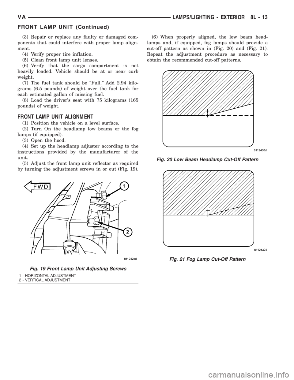
(5) Adjust the front lamp unit reflector as required
by turning the adjustment screws in or out (Fig. 19).(6) When properly aligned, the low beam head-
lamps and, if equipped, fog lamps should provide a
cut-off pattern as shown in (Fig. 20) and (Fig. 21).
Repeat the adjustment procedure as necessary to
obtain the recommended cut-off patterns.
Fig. 19 Front Lamp Unit Adjusting Screws
1 - HORIZONTAL ADJUSTMENT
2 - VERTICAL ADJUSTMENT
Fig. 20 Low Beam Headlamp Cut-Off Pattern
Fig. 21 Fog Lamp Cut-Off Pattern
VALAMPS/LIGHTING - EXTERIOR 8L - 13
FRONT LAMP UNIT (Continued)
Page 242 of 1232
splices, splice block connectors, and many different
types of wire harness terminal connectors and insu-
lators. Refer to the appropriate wiring information.
The wiring information includes wiring diagrams,
proper wire and connector repair procedures, further
details on wire harness routing and retention, as well
as pin-out and location views for the various wire
harness connectors, splices and grounds.
OPERATION
ACTIVE RESTRAINTS
The primary passenger restraints in this or any
other vehicle are the standard equipment factory-in-
stalled seat belts. Seat belts are referred to as an
active restraint because the vehicle occupants are
required to physically fasten and properly adjust
these restraints in order to benefit from them. See
the owner's manual in the vehicle glove box for more
information on the features, use and operation of all
of the factory-installed active restraints.
PASSIVE RESTRAINTS
The passive restraints are referred to as a supple-
mental restraint system because they were designed
and are intended to enhance the protection for the
occupants of the vehicleonlywhen used in conjunc-
tion with the seat belts. They are referred to as pas-
sive restraints because the vehicle occupants are not
required to do anything to make them operate; how-
ever, the vehicle occupants must be wearing their
seat belts in order to obtain the maximum safety
benefit from the factory-installed supplemental
restraint system.
The supplemental restraint system electrical cir-
cuits are continuously monitored and controlled by a
microprocessor and software contained within the
Airbag Control Module (ACM). An airbag indicator in
the ElectroMechanical Instrument Cluster (EMIC)
illuminates for about four seconds as a bulb test each
time the ignition switch is turned to the On or Start
positions. Following the bulb test, the airbag indica-
tor is turned on or off by the ACM to indicate the
status of the supplemental restraint system. If the
airbag indicator comes on either solid or flashing at
any time other than during the bulb test, it indicates
that there is a problem in the supplemental restraint
system electrical circuits. Such a problem may cause
airbags not to deploy when required, or to deploy
when not required.
Deployment of the supplemental restraints
depends upon the angle and severity of an impact.Deployment is not based upon vehicle speed; rather,
deployment is based upon the rate of deceleration as
measured by the forces of gravity (G force) upon the
impact sensor. When an impact is severe enough, the
microprocessor in the ACM signals the inflator of the
appropriate airbag units to deploy their airbag cush-
ions. The front seat belt tensioners are provided with
a deployment signal by the ACM in conjunction with
the driver and passenger airbags. During a frontal
vehicle impact, the knee blockers work in concert
with properly fastened and adjusted seat belts to
restrain both the driver and the front seat passenger
in the proper position for an airbag deployment. The
knee blockers also absorb and distribute the crash
energy from the driver and the front seat passenger
to the structure of the instrument panel. The seat
belt tensioners remove the slack from the front seat
belts to provide further assurance that the driver and
front seat passenger are properly positioned and
restrained for an airbag deployment.
Typically, the vehicle occupants recall more about
the events preceding and following a collision than
they do of an airbag deployment itself. This is
because the airbag deployment and deflation occur so
rapidly. In a typical 48 kilometer-per-hour (30 mile-
per-hour) barrier impact, from the moment of impact
until the airbags are fully inflated takes only a few
milliseconds. Within one to two seconds from the
moment of impact, the airbags are almost entirely
deflated. The times cited for these events are approx-
imations, which apply only to a barrier impact at the
given speed. Actual times will vary somewhat,
depending upon the vehicle speed, impact angle,
severity of the impact, and the type of collision.
When the ACM monitors a problem in any of the
front airbag system circuits or components, including
the seat belt tensioners, it stores a fault code or
Diagnostic Trouble Code (DTC) in its memory circuit
and sends a hard wired output to the EMIC to turn
on the airbag indicator. If the EMIC detects a prob-
lem in the airbag indicator or airbag indicator circuit,
the cluster will flash the seatbelt indicator on and
off. Proper testing of the supplemental restraint sys-
tem components as well as the retrieval or erasure of
a DTC from the ACM requires the use of a DRBIIIt
scan tool. Refer to the appropriate diagnostic infor-
mation.
See the owner's manual in the vehicle glove box for
more information on the features, use and operation
of all of the factory-installed passive restraints.
8O - 4 RESTRAINTSVA
RESTRAINTS (Continued)
Page 250 of 1232
(1) Reconnect and latch the vehicle wire harness
connector for the ACM to the ACM connector recep-
tacle located on the left facing side of the module
(Fig. 12).
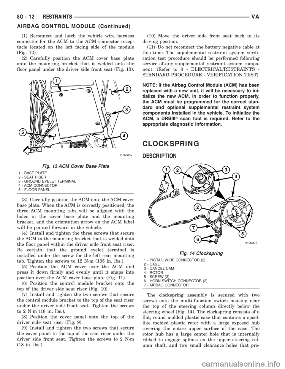
(2) Carefully position the ACM cover base plate
onto the mounting bracket that is welded onto the
floor panel under the driver side front seat (Fig. 13).
(3) Carefully position the ACM onto the ACM cover
base plate. When the ACM is correctly positioned, the
three ACM mounting tabs will be aligned with the
holes in the cover base plate and the mounting
bracket, and the orientation arrow on the ACM label
will be pointed forward in the vehicle.
(4) Install and tighten the three screws that secure
the ACM to the mounting bracket that is welded onto
the floor panel within the driver side front seat riser.
Be certain that the ground eyelet terminal is
installed under the screw for the left rear mounting
tab. Tighten the screws to 12 N´m (105 in. lbs.).
(5) Position the ACM cover over the ACM and
press it down firmly and evenly until it snaps into
position over the ACM cover base plate (Fig. 11).
(6) Position the control module bracket onto the
top of the driver side seat riser (Fig. 10).
(7) Install and tighten the two screws that secure
the control module bracket to the top of the seat riser
under the driver side front seat. Tighten the screws
to 2 N´m (18 in. lbs.).
(8) Position the cover panel onto the top of the
driver side seat riser (Fig. 9).
(9) Install and tighten the two screws that secure
the cover panel to the top of the seat riser under the
driver side front seat. Tighten the screws to 2 N´m
(18 in. lbs.).(10) Move the driver side front seat back to its
driving position.
(11) Do not reconnect the battery negative cable at
this time. The supplemental restraint system verifi-
cation test procedure should be performed following
service of any supplemental restraint system compo-
nent. (Refer to 8 - ELECTRICAL/RESTRAINTS -
STANDARD PROCEDURE - VERIFICATION TEST).
NOTE: If the Airbag Control Module (ACM) has been
replaced with a new unit, it will be necessary to ini-
tialize the new ACM. In order to function properly,
the ACM must be programmed for the correct stan-
dard and optional supplemental restraint system
components installed in the vehicle. To initialize the
ACM, a DRBIIITscan tool is required. Refer to the
appropriate diagnostic information.
CLOCKSPRING
DESCRIPTION
The clockspring assembly is secured with two
screws onto the multi-function switch housing near
the top of the steering column directly below the
steering wheel (Fig. 14). The clockspring consists of a
flat, round molded plastic case that contains a spool-
like molded plastic rotor with a large exposed hub
covering the entire upper surface of the case. The
rotor hub has a large center hole that is internally
ribbed to engage splines on the upper steering col-
umn shaft, and two small clearance holes that pro-
Fig. 13 ACM Cover Base Plate
1 - BASE PLATE
2 - SEAT RISER
3 - GROUND EYELET TERMINAL
4 - ACM CONNECTOR
5 - FLOOR PANEL
Fig. 14 Clockspring
1 - PIGTAIL WIRE CONNECTOR (2)
2 - CASE
3 - CANCEL CAM
4 - ROTOR
5 - SCREW (2)
6 - HORN SWITCH CONNECTOR (2)
7 - AIRBAG CONNECTOR
8O - 12 RESTRAINTSVA
AIRBAG CONTROL MODULE (Continued)
Page 1025 of 1232
TIRES/WHEELS
TABLE OF CONTENTS
page page
TIRES/WHEELS
DIAGNOSIS AND TESTING - TIRE AND
WHEEL RUNOUT......................1
STANDARD PROCEDURE
STANDARD PROCEDURE - MATCH
MOUNTING...........................2
STANDARD PROCEDURE - TIRE AND
WHEEL BALANCE......................3
STANDARD PROCEDURE - TIRE ROTATION . 5
SPECIFICATIONS
TORQUE CHART......................5
TIRES
DESCRIPTION
DESCRIPTION - TIRES..................6
DESCRIPTION - RADIAL ± PLY TIRES......6
DESCRIPTION - TIRE PRESSURE FOR
HIGH SPEEDS.........................6
DESCRIPTION - REPLACEMENT TIRES.....7
DESCRIPTION - TIRE INFLATION
PRESSURES..........................7
DIAGNOSIS AND TESTING
DIAGNOSIS AND TESTING - PRESSURE
GAUGES.............................8
DIAGNOSIS AND TESTING - TIRE NOISE
OR VIBRATION........................8
DIAGNOSIS AND TESTING - TREAD WEAR
INDICATORS..........................8DIAGNOSIS AND TESTING - TIRE WEAR
PATTERNS...........................8
DIAGNOSIS AND TESTING - TIRE/VEHICLE
LEAD................................8
STANDARD PROCEDURE - REPAIRING
LEAKS..............................10
CLEANING............................10
SPECIFICATIONS
TIRES..............................10
SPARE TIRE CARRIER
REMOVAL.............................10
INSTALLATION.........................10
WHEELS
DESCRIPTION.........................11
OPERATION...........................11
DIAGNOSIS AND TESTING
WHEEL INSPECTION..................11
STANDARD PROCEDURE
STANDARD PROCEDURE - WHEEL
REPLACEMENT.......................11
STANDARD PROCEDURE - DUAL REAR
WHEEL INSTALLATION.................12
REMOVAL.............................13
INSTALLATION.........................13
TIRES/WHEELS
DIAGNOSIS AND TESTING - TIRE AND WHEEL
RUNOUT
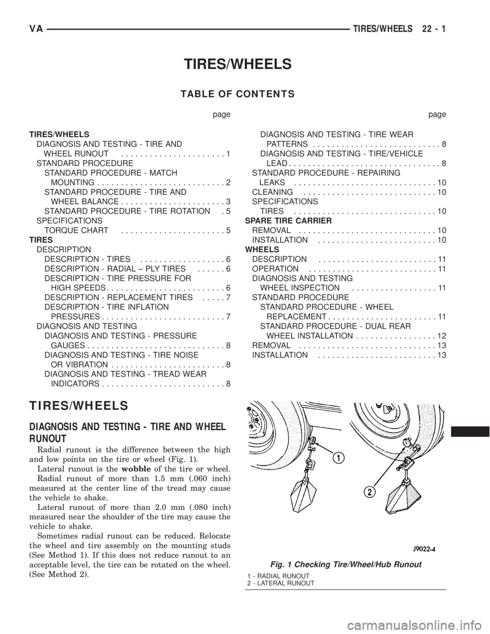
Radial runout is the difference between the high
and low points on the tire or wheel (Fig. 1).
Lateral runout is thewobbleof the tire or wheel.
Radial runout of more than 1.5 mm (.060 inch)
measured at the center line of the tread may cause
the vehicle to shake.
Lateral runout of more than 2.0 mm (.080 inch)
measured near the shoulder of the tire may cause the
vehicle to shake.
Sometimes radial runout can be reduced. Relocate
the wheel and tire assembly on the mounting studs
(See Method 1). If this does not reduce runout to an
acceptable level, the tire can be rotated on the wheel.
(See Method 2).
Fig. 1 Checking Tire/Wheel/Hub Runout
1 - RADIAL RUNOUT
2 - LATERAL RUNOUT
VATIRES/WHEELS 22 - 1