2005 MERCEDES-BENZ SPRINTER plugs
[x] Cancel search: plugsPage 73 of 1232
BRAKE PADS/SHOES
REMOVAL
REMOVAL - FRONT (SRW)
(1) Unscrew the cap from the brake fluid reservoir.
(2) Raise and support the vehicle.
(3) Remove the front wheels (Refer to 22 - TIRES/
WHEELS/WHEELS - REMOVAL).
(4) Remove the wear indicator cable and the wear
indicator (Fig. 4).
NOTE: Seal off the line ends and connection
threads in the brake calipers with plugs. Also check
brake hoses for signs of cracks.
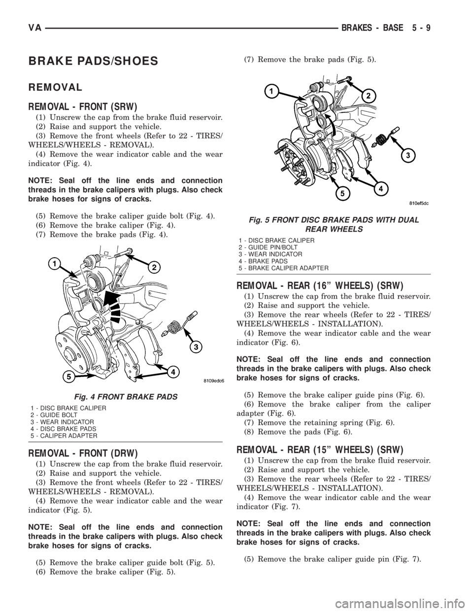
(5) Remove the brake caliper guide bolt (Fig. 4).
(6) Remove the brake caliper (Fig. 4).
(7) Remove the brake pads (Fig. 4).
REMOVAL - FRONT (DRW)
(1) Unscrew the cap from the brake fluid reservoir.
(2) Raise and support the vehicle.
(3) Remove the front wheels (Refer to 22 - TIRES/
WHEELS/WHEELS - REMOVAL).
(4) Remove the wear indicator cable and the wear
indicator (Fig. 5).
NOTE: Seal off the line ends and connection
threads in the brake calipers with plugs. Also check
brake hoses for signs of cracks.
(5) Remove the brake caliper guide bolt (Fig. 5).
(6) Remove the brake caliper (Fig. 5).(7) Remove the brake pads (Fig. 5).
REMOVAL - REAR (16º WHEELS) (SRW)
(1) Unscrew the cap from the brake fluid reservoir.
(2) Raise and support the vehicle.
(3) Remove the rear wheels (Refer to 22 - TIRES/
WHEELS/WHEELS - INSTALLATION).
(4) Remove the wear indicator cable and the wear
indicator (Fig. 6).
NOTE: Seal off the line ends and connection
threads in the brake calipers with plugs. Also check
brake hoses for signs of cracks.
(5) Remove the brake caliper guide pins (Fig. 6).
(6) Remove the brake caliper from the caliper
adapter (Fig. 6).
(7) Remove the retaining spring (Fig. 6).
(8) Remove the pads (Fig. 6).
REMOVAL - REAR (15º WHEELS) (SRW)
(1) Unscrew the cap from the brake fluid reservoir.
(2) Raise and support the vehicle.
(3) Remove the rear wheels (Refer to 22 - TIRES/
WHEELS/WHEELS - INSTALLATION).
(4) Remove the wear indicator cable and the wear
indicator (Fig. 7).
NOTE: Seal off the line ends and connection
threads in the brake calipers with plugs. Also check
brake hoses for signs of cracks.
(5) Remove the brake caliper guide pin (Fig. 7).
Fig. 4 FRONT BRAKE PADS
1 - DISC BRAKE CALIPER
2 - GUIDE BOLT
3 - WEAR INDICATOR
4 - DISC BRAKE PADS
5 - CALIPER ADAPTER
Fig. 5 FRONT DISC BRAKE PADS WITH DUAL
REAR WHEELS
1 - DISC BRAKE CALIPER
2 - GUIDE PIN/BOLT
3 - WEAR INDICATOR
4 - BRAKE PADS
5 - BRAKE CALIPER ADAPTER
VABRAKES - BASE 5 - 9
Page 74 of 1232
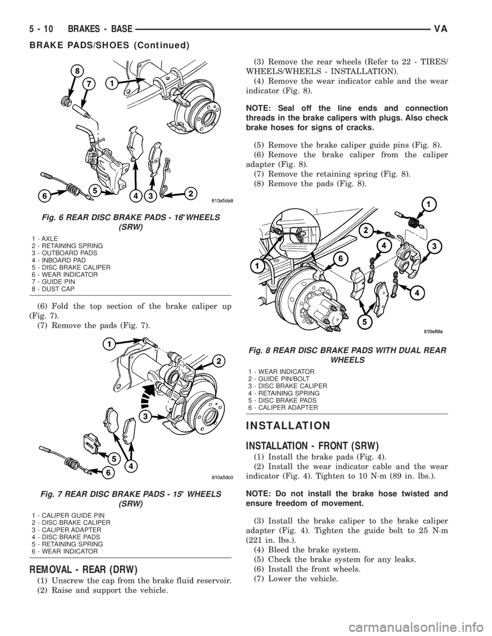
(6) Fold the top section of the brake caliper up
(Fig. 7).
(7) Remove the pads (Fig. 7).
REMOVAL - REAR (DRW)
(1) Unscrew the cap from the brake fluid reservoir.
(2) Raise and support the vehicle.(3) Remove the rear wheels (Refer to 22 - TIRES/
WHEELS/WHEELS - INSTALLATION).
(4) Remove the wear indicator cable and the wear
indicator (Fig. 8).
NOTE: Seal off the line ends and connection
threads in the brake calipers with plugs. Also check
brake hoses for signs of cracks.
(5) Remove the brake caliper guide pins (Fig. 8).
(6) Remove the brake caliper from the caliper
adapter (Fig. 8).
(7) Remove the retaining spring (Fig. 8).
(8) Remove the pads (Fig. 8).
INSTALLATION
INSTALLATION - FRONT (SRW)
(1) Install the brake pads (Fig. 4).
(2) Install the wear indicator cable and the wear
indicator (Fig. 4). Tighten to 10 N´m (89 in. lbs.).
NOTE: Do not install the brake hose twisted and
ensure freedom of movement.
(3) Install the brake caliper to the brake caliper
adapter (Fig. 4). Tighten the guide bolt to 25 N´m
(221 in. lbs.).
(4) Bleed the brake system.
(5) Check the brake system for any leaks.
(6) Install the front wheels.
(7) Lower the vehicle.
Fig. 6 REAR DISC BRAKE PADS - 16(WHEELS
(SRW)
1 - AXLE
2 - RETAINING SPRING
3 - OUTBOARD PADS
4 - INBOARD PAD
5 - DISC BRAKE CALIPER
6 - WEAR INDICATOR
7 - GUIDE PIN
8 - DUST CAP
Fig. 7 REAR DISC BRAKE PADS - 15(WHEELS
(SRW)
1 - CALIPER GUIDE PIN
2 - DISC BRAKE CALIPER
3 - CALIPER ADAPTER
4 - DISC BRAKE PADS
5 - RETAINING SPRING
6 - WEAR INDICATOR
Fig. 8 REAR DISC BRAKE PADS WITH DUAL REAR
WHEELS
1 - WEAR INDICATOR
2 - GUIDE PIN/BOLT
3 - DISC BRAKE CALIPER
4 - RETAINING SPRING
5 - DISC BRAKE PADS
6 - CALIPER ADAPTER
5 - 10 BRAKES - BASEVA
BRAKE PADS/SHOES (Continued)
Page 75 of 1232
INSTALLATION - FRONT (DRW)
(1) Install the brake pads (Fig. 5).
(2) Install the wear indicator cable and the wear
indicator (Fig. 5). Tighten to 10 N´m (89 in. lbs.).
NOTE: Do not install the brake hose twisted and
ensure freedom of movement.
(3) Install the brake caliper to the brake caliper
adapter (Fig. 5). Tighten the guide bolt to 25 N´m
(221 in. lbs.)(M8 bolt) or Tighten the guide bolt to 30
N´m (265 in. lbs.)(M10 10.9 bolt).
(4) Bleed the brake system.
(5) Check the brake system for any leaks.
(6) Install the front wheels.
(7) Lower the vehicle.
INSTALLATION - REAR (16º WHEELS) (SRW)
(1) Install the brake pads (Fig. 6).
(2) Install the wear indicator cable and the wear
indicator (Fig. 6). Tighten to 10 N´m (89 in. lbs.).
NOTE: Do not install the brake hose twisted and
ensure freedom of movement.
(3) Install the brake caliper to brake caliper
adapter (Fig. 6). Tighten the guide pins to 25 N´m
(221 in. lbs.) for M8 bolt or 30 N´m (266 in. lbs.) for
M10 bolt.
(4) Install the retaining spring (Fig. 6).
(5) Install the rear wheels (Refer to 22 - TIRES/
WHEELS/WHEELS - INSTALLATION).
(6) Lower the vehicle.
INSTALLATION - REAR (16º WHEELS) (SRW)
(1) Install the brake pads (Fig. 7).
(2) Install the wear indicator cable and the wear
indicator (Fig. 7). Tighten to 10 N´m (89 in. lbs.).
NOTE: Do not install the brake hose twisted and
ensure freedom of movement.
(3) Install the brake caliper to brake caliper
adapter (Fig. 7). Tighten the guide pin to 30 N´m
(266 in. lbs.) for M10 bolt.
(4) Install the rear wheels (Refer to 22 - TIRES/
WHEELS/WHEELS - INSTALLATION).
(5) Lower the vehicle.
INSTALLATION - REAR (DRW)
(1) Install the brake pads (Fig. 8).
(2) Install the wear indicator cable and the wear
indicator (Fig. 8). Tighten to 10 N´m (89 in. lbs.).
NOTE: Do not install the brake hose twisted and
ensure freedom of movement.(3) Install the brake caliper to brake caliper
adapter (Fig. 8). Tighten the guide pins to 25 N´m
(221 in. lbs.) for M8 bolt or 30 N´m (266 in. lbs.) for
M10 10.9 bolt.
(4) Install the retaining spring (Fig. 8).
(5) Install the rear wheels (Refer to 22 - TIRES/
WHEELS/WHEELS - INSTALLATION).
(6) Lower the vehicle.
DISC BRAKE CALIPERS
REMOVAL
REMOVAL - FRONT (SRW)
(1) Unscrew the cap from the brake fluid reservoir.
(2) Raise and support the vehicle.
(3) Remove the front wheels (Refer to 22 - TIRES/
WHEELS/WHEELS - REMOVAL).
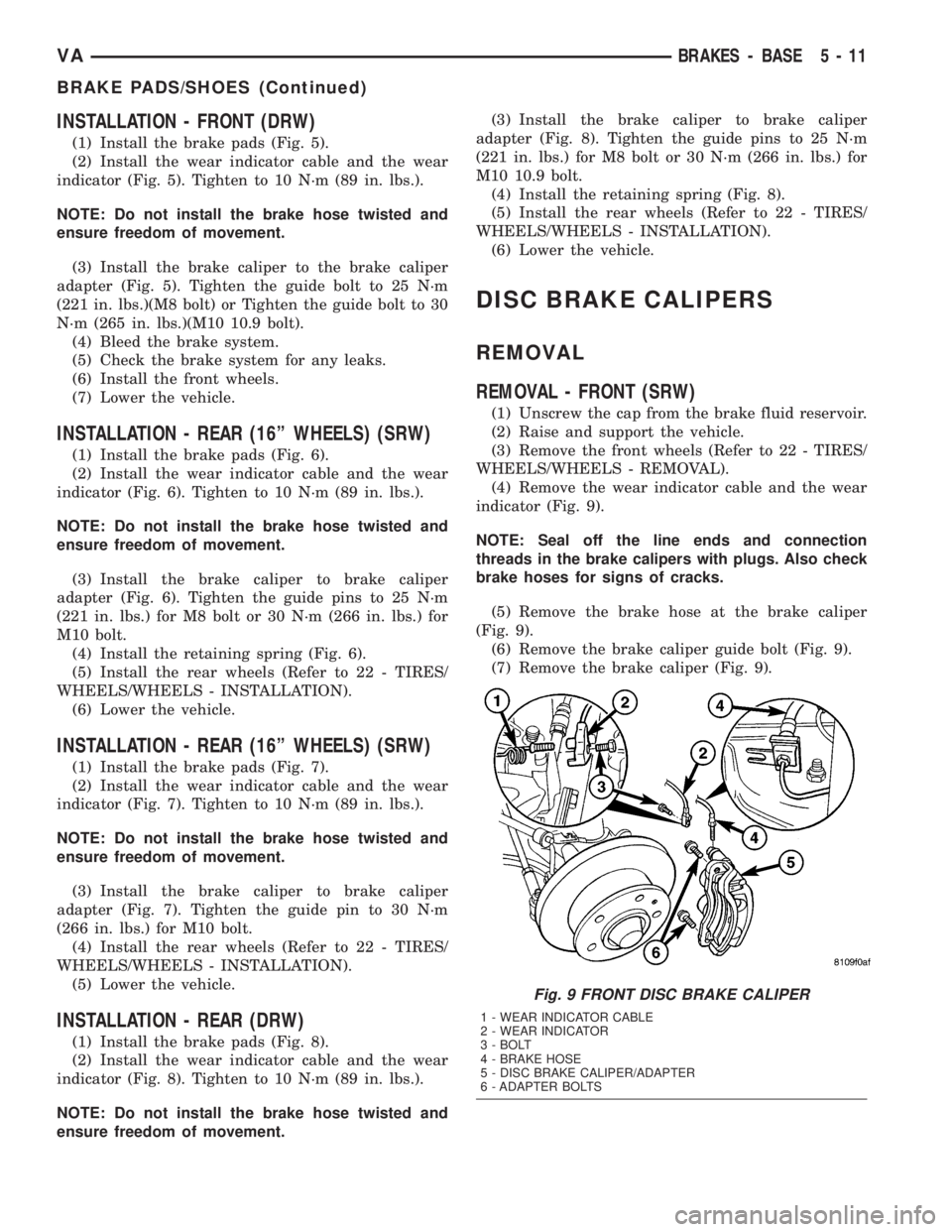
(4) Remove the wear indicator cable and the wear
indicator (Fig. 9).
NOTE: Seal off the line ends and connection
threads in the brake calipers with plugs. Also check
brake hoses for signs of cracks.
(5) Remove the brake hose at the brake caliper
(Fig. 9).
(6) Remove the brake caliper guide bolt (Fig. 9).
(7) Remove the brake caliper (Fig. 9).
Fig. 9 FRONT DISC BRAKE CALIPER
1 - WEAR INDICATOR CABLE
2 - WEAR INDICATOR
3 - BOLT
4 - BRAKE HOSE
5 - DISC BRAKE CALIPER/ADAPTER
6 - ADAPTER BOLTS
VABRAKES - BASE 5 - 11
BRAKE PADS/SHOES (Continued)
Page 76 of 1232
REMOVAL - FRONT (DRW)
(1) Unscrew the cap from the brake fluid reservoir.
(2) Raise and support the vehicle.
(3) Remove the front wheels (Refer to 22 - TIRES/
WHEELS/WHEELS - REMOVAL).
(4) Remove the wear indicator cable and the wear
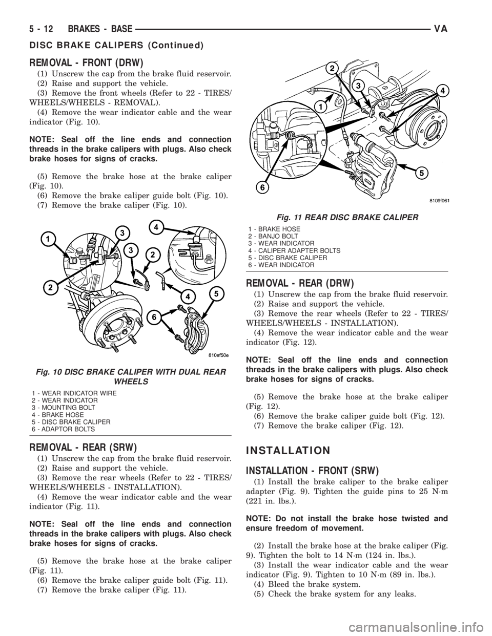
indicator (Fig. 10).
NOTE: Seal off the line ends and connection
threads in the brake calipers with plugs. Also check
brake hoses for signs of cracks.
(5) Remove the brake hose at the brake caliper
(Fig. 10).
(6) Remove the brake caliper guide bolt (Fig. 10).
(7) Remove the brake caliper (Fig. 10).
REMOVAL - REAR (SRW)
(1) Unscrew the cap from the brake fluid reservoir.
(2) Raise and support the vehicle.
(3) Remove the rear wheels (Refer to 22 - TIRES/
WHEELS/WHEELS - INSTALLATION).
(4) Remove the wear indicator cable and the wear
indicator (Fig. 11).
NOTE: Seal off the line ends and connection
threads in the brake calipers with plugs. Also check
brake hoses for signs of cracks.
(5) Remove the brake hose at the brake caliper
(Fig. 11).
(6) Remove the brake caliper guide bolt (Fig. 11).
(7) Remove the brake caliper (Fig. 11).
REMOVAL - REAR (DRW)
(1) Unscrew the cap from the brake fluid reservoir.
(2) Raise and support the vehicle.
(3) Remove the rear wheels (Refer to 22 - TIRES/
WHEELS/WHEELS - INSTALLATION).
(4) Remove the wear indicator cable and the wear
indicator (Fig. 12).
NOTE: Seal off the line ends and connection
threads in the brake calipers with plugs. Also check
brake hoses for signs of cracks.
(5) Remove the brake hose at the brake caliper
(Fig. 12).
(6) Remove the brake caliper guide bolt (Fig. 12).
(7) Remove the brake caliper (Fig. 12).
INSTALLATION
INSTALLATION - FRONT (SRW)
(1) Install the brake caliper to the brake caliper
adapter (Fig. 9). Tighten the guide pins to 25 N´m
(221 in. lbs.).
NOTE: Do not install the brake hose twisted and
ensure freedom of movement.
(2) Install the brake hose at the brake caliper (Fig.
9). Tighten the bolt to 14 N´m (124 in. lbs.).
(3) Install the wear indicator cable and the wear
indicator (Fig. 9). Tighten to 10 N´m (89 in. lbs.).
(4) Bleed the brake system.
(5) Check the brake system for any leaks.
Fig. 10 DISC BRAKE CALIPER WITH DUAL REAR
WHEELS
1 - WEAR INDICATOR WIRE
2 - WEAR INDICATOR
3 - MOUNTING BOLT
4 - BRAKE HOSE
5 - DISC BRAKE CALIPER
6 - ADAPTOR BOLTS
Fig. 11 REAR DISC BRAKE CALIPER
1 - BRAKE HOSE
2 - BANJO BOLT
3 - WEAR INDICATOR
4 - CALIPER ADAPTER BOLTS
5 - DISC BRAKE CALIPER
6 - WEAR INDICATOR
5 - 12 BRAKES - BASEVA
DISC BRAKE CALIPERS (Continued)
Page 79 of 1232
FLUID RESERVOIR
REMOVAL
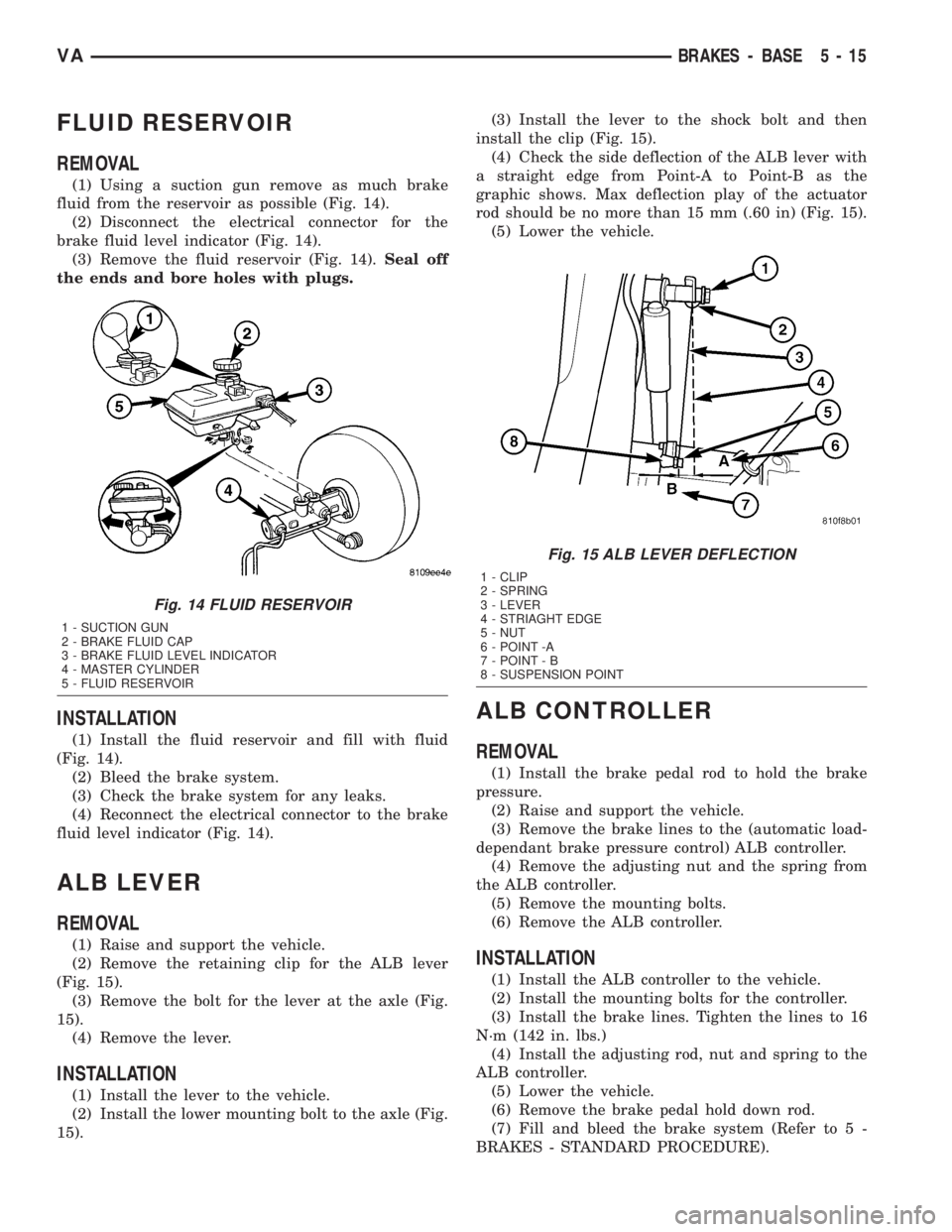
(1) Using a suction gun remove as much brake
fluid from the reservoir as possible (Fig. 14).
(2) Disconnect the electrical connector for the
brake fluid level indicator (Fig. 14).
(3) Remove the fluid reservoir (Fig. 14).Seal off
the ends and bore holes with plugs.
INSTALLATION
(1) Install the fluid reservoir and fill with fluid
(Fig. 14).
(2) Bleed the brake system.
(3) Check the brake system for any leaks.
(4) Reconnect the electrical connector to the brake
fluid level indicator (Fig. 14).
ALB LEVER
REMOVAL
(1) Raise and support the vehicle.
(2) Remove the retaining clip for the ALB lever
(Fig. 15).
(3) Remove the bolt for the lever at the axle (Fig.
15).
(4) Remove the lever.
INSTALLATION
(1) Install the lever to the vehicle.
(2) Install the lower mounting bolt to the axle (Fig.
15).(3) Install the lever to the shock bolt and then
install the clip (Fig. 15).
(4) Check the side deflection of the ALB lever with
a straight edge from Point-A to Point-B as the
graphic shows. Max deflection play of the actuator
rod should be no more than 15 mm (.60 in) (Fig. 15).
(5) Lower the vehicle.
ALB CONTROLLER
REMOVAL
(1) Install the brake pedal rod to hold the brake
pressure.
(2) Raise and support the vehicle.
(3) Remove the brake lines to the (automatic load-
dependant brake pressure control) ALB controller.
(4) Remove the adjusting nut and the spring from
the ALB controller.
(5) Remove the mounting bolts.
(6) Remove the ALB controller.
INSTALLATION
(1) Install the ALB controller to the vehicle.
(2) Install the mounting bolts for the controller.
(3) Install the brake lines. Tighten the lines to 16
N´m (142 in. lbs.)
(4) Install the adjusting rod, nut and spring to the
ALB controller.
(5) Lower the vehicle.
(6) Remove the brake pedal hold down rod.
(7) Fill and bleed the brake system (Refer to 5 -
BRAKES - STANDARD PROCEDURE).
Fig. 14 FLUID RESERVOIR
1 - SUCTION GUN
2 - BRAKE FLUID CAP
3 - BRAKE FLUID LEVEL INDICATOR
4 - MASTER CYLINDER
5 - FLUID RESERVOIR
Fig. 15 ALB LEVER DEFLECTION
1 - CLIP
2 - SPRING
3 - LEVER
4 - STRIAGHT EDGE
5 - NUT
6 - POINT -A
7 - POINT - B
8 - SUSPENSION POINT
VABRAKES - BASE 5 - 15
Page 82 of 1232
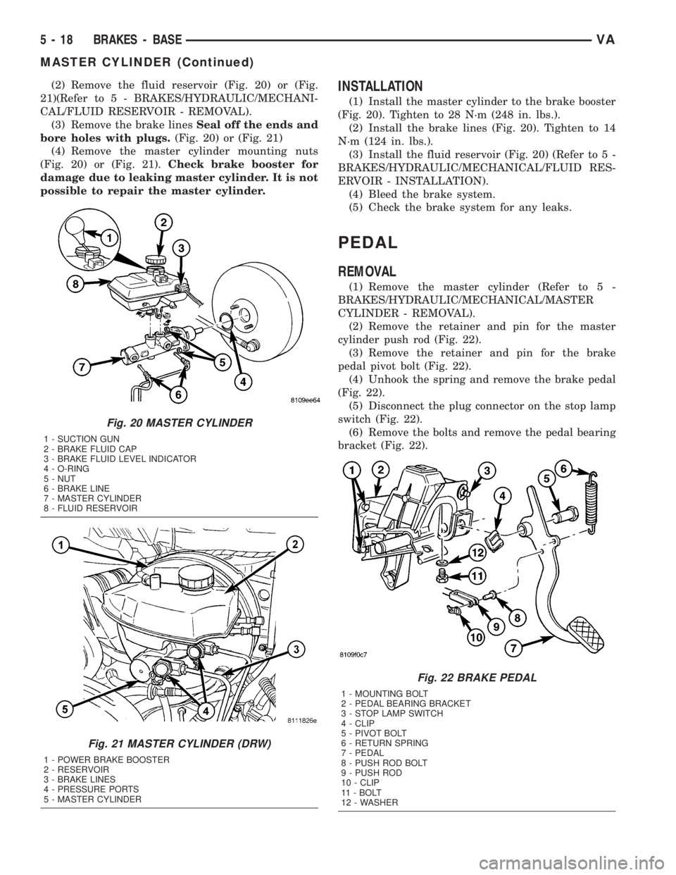
(2) Remove the fluid reservoir (Fig. 20) or (Fig.
21)(Refer to 5 - BRAKES/HYDRAULIC/MECHANI-
CAL/FLUID RESERVOIR - REMOVAL).
(3) Remove the brake linesSeal off the ends and
bore holes with plugs.(Fig. 20) or (Fig. 21)
(4) Remove the master cylinder mounting nuts
(Fig. 20) or (Fig. 21).Check brake booster for
damage due to leaking master cylinder. It is not
possible to repair the master cylinder.INSTALLATION
(1) Install the master cylinder to the brake booster
(Fig. 20). Tighten to 28 N´m (248 in. lbs.).
(2) Install the brake lines (Fig. 20). Tighten to 14
N´m (124 in. lbs.).
(3) Install the fluid reservoir (Fig. 20) (Refer to 5 -
BRAKES/HYDRAULIC/MECHANICAL/FLUID RES-
ERVOIR - INSTALLATION).
(4) Bleed the brake system.
(5) Check the brake system for any leaks.
PEDAL
REMOVAL
(1) Remove the master cylinder (Refer to 5 -
BRAKES/HYDRAULIC/MECHANICAL/MASTER
CYLINDER - REMOVAL).
(2) Remove the retainer and pin for the master
cylinder push rod (Fig. 22).
(3) Remove the retainer and pin for the brake
pedal pivot bolt (Fig. 22).
(4) Unhook the spring and remove the brake pedal
(Fig. 22).
(5) Disconnect the plug connector on the stop lamp
switch (Fig. 22).
(6) Remove the bolts and remove the pedal bearing
bracket (Fig. 22).
Fig. 20 MASTER CYLINDER
1 - SUCTION GUN
2 - BRAKE FLUID CAP
3 - BRAKE FLUID LEVEL INDICATOR
4 - O-RING
5 - NUT
6 - BRAKE LINE
7 - MASTER CYLINDER
8 - FLUID RESERVOIR
Fig. 21 MASTER CYLINDER (DRW)
1 - POWER BRAKE BOOSTER
2 - RESERVOIR
3 - BRAKE LINES
4 - PRESSURE PORTS
5 - MASTER CYLINDER
Fig. 22 BRAKE PEDAL
1 - MOUNTING BOLT
2 - PEDAL BEARING BRACKET
3 - STOP LAMP SWITCH
4 - CLIP
5 - PIVOT BOLT
6 - RETURN SPRING
7 - PEDAL
8 - PUSH ROD BOLT
9 - PUSH ROD
10 - CLIP
11 - BOLT
12 - WASHER
5 - 18 BRAKES - BASEVA
MASTER CYLINDER (Continued)
Page 83 of 1232
INSTALLATION
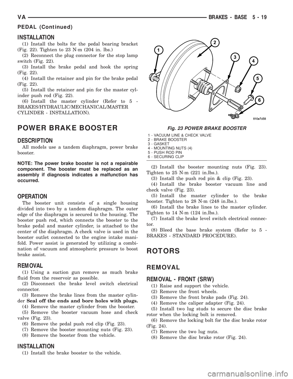
(1) Install the bolts for the pedal bearing bracket
(Fig. 22). Tighten to 23 N´m (204 in. lbs.)
(2) Reconnect the plug connector for the stop lamp
switch (Fig. 22).
(3) Install the brake pedal and hook the spring
(Fig. 22).
(4) Install the retainer and pin for the brake pedal
(Fig. 22).
(5) Install the retainer and pin for the master cyl-
inder push rod (Fig. 22).
(6) Install the master cylinder (Refer to 5 -
BRAKES/HYDRAULIC/MECHANICAL/MASTER
CYLINDER - INSTALLATION).
POWER BRAKE BOOSTER
DESCRIPTION
All models use a tandem diaphragm, power brake
booster.
NOTE: The power brake booster is not a repairable
component. The booster must be replaced as an
assembly if diagnosis indicates a malfunction has
occurred.
OPERATION
The booster unit consists of a single housing
divided into two by a tandem diaphragm. The outer
edge of the diaphragm is secured to the housing. The
booster push rod, which connects the booster to the
brake pedal and master cylinder, is attached to the
center of the diaphragm. A check valve is used in the
booster outlet connected to the engine intake mani-
fold. Power assist is generated by utilizing a combi-
nation of vacuum and atmospheric pressure to boost
brake assist.
REMOVAL
(1) Using a suction gun remove as much brake
fluid from the reservoir as possible.
(2) Disconnect the brake level switch electrical
connector.
(3) Remove the brake lines from the master cylin-
derSeal off the ends and bore holes with plugs.
(4) Remove the master cylinder from the booster.
(5) Remove the booster vacuum hose and check
valve (Fig. 23).
(6) Remove the pedal push rod clip (Fig. 23).
(7) Remove the booster mounting nuts (Fig. 23).
(8) Remove the booster from the vehicle.
INSTALLATION
(1) Install the brake booster to the vehicle.(2) Install the booster mounting nuts (Fig. 23).
Tighten to 25 N´m (221 in.lbs.).
(3) Install the push rod pin & clip (Fig. 23).
(4) Install the brake booster vacuum line and
check valve (Fig. 23).
(5) Install the master cylinder to the brake
booster. Tighten to 28 N´m (248 in.lbs.).
(6) Install the brake lines to the master cylinder.
Tighten to 14 N´m (124 in.lbs.).
(7) Install the brake level switch electrical connec-
tor.
(8) Bleed the base brake system (Refer to 5 -
BRAKES - STANDARD PROCEDURE).
ROTORS
REMOVAL
REMOVAL - FRONT (SRW)
(1) Raise and support the vehicle.
(2) Remove the front wheels.
(3) Remove the front brake pads (Fig. 24).
(4) Remove the caliper adapter (Fig. 24).
(5) Install two lug studs to secure the disc brake
rotor when the locking bolt is removed.
(6) Remove the locking bolt for the disc brake rotor
(Fig. 24).
(7) Remove the two lug nuts.
(8) Remove the disc brake rotor (Fig. 24).
Fig. 23 POWER BRAKE BOOSTER
1 - VACUUM LINE & CHECK VALVE
2 - BRAKE BOOSTER
3 - GASKET
4 - MOUNTING NUTS (4)
5 - PUSH ROD PIN
6 - SECURING CLIP
VABRAKES - BASE 5 - 19
PEDAL (Continued)
Page 107 of 1232
Operate tester pump to apply 103.4 kPa (15 psi)
pressure to system. If hoses enlarge excessively or
bulges while testing, replace as necessary. Observe
gauge pointer and determine condition of cooling sys-
tem according to following criteria:
Holds Steady:If pointer remains steady for two
minutes, serious coolant leaks are not present in sys-
tem. However, there could be an internal leak that
does not appear with normal system test pressure. If
it is certain that coolant is being lost and leaks can-
not be detected, inspect for interior leakage or per-
form Internal Leakage Test.
Drops Slowly:Indicates a small leak or seepage
is occurring. Examine all connections for seepage or
slight leakage with a flashlight. Inspect radiator,
hoses, gasket edges and heater. Seal small leak holes
with a Sealer Lubricant (or equivalent). Repair leak
holes and inspect system again with pressure
applied.
Drops Quickly:Indicates that serious leakage is
occurring. Examine system for external leakage. If
leaks are not visible, inspect for internal leakage.
Large radiator leak holes should be repaired by a
reputable radiator repair shop.
INTERNAL LEAKAGE INSPECTION
Remove engine oil pan drain plug and drain a
small amount of engine oil. If coolant is present in
the pan, it will drain first because it is heavier than
oil. An alternative method is to operate engine for a
short period to churn the oil. After this is done,
remove engine dipstick and inspect for water glob-
ules. Also inspect transmission dipstick for water
globules and transmission fluid cooler for leakage.
WARNING: WITH RADIATOR PRESSURE TESTER
TOOL INSTALLED ON RADIATOR, DO NOT ALLOW
PRESSURE TO EXCEED 110 KPA (20 PSI). PRES-
SURE WILL BUILD UP QUICKLY IF A COMBUSTION
LEAK IS PRESENT. TO RELEASE PRESSURE,
ROCK TESTER FROM SIDE TO SIDE. WHEN
REMOVING TESTER, DO NOT TURN TESTER MORE
THAN 1/2 TURN IF SYSTEM IS UNDER PRESSURE.
Operate engine without pressure cap on coolant
container until thermostat opens. Attach a Pressure
Tester to container. If pressure builds up quickly it
indicates a combustion leak exists. This is usually
the result of a cylinder head gasket leak or crack in
engine. Repair as necessary.
If there is not an immediate pressure increase,
pump the Pressure Tester. Do this until indicated
pressure is within system range of 110 kPa (16 psi).
Fluctuation of gauge pointer indicates compression or
combustion leakage into cooling system.Because the vehicle is equipped with a catalytic
converter,do notremove spark plug cables or short
out cylinders to isolate compression leak.
If the needle on dial of pressure tester does not
fluctuate, race engine a few times to check for an
abnormal amount of coolant or steam. This would be
emitting from exhaust pipe. Coolant or steam from
exhaust pipe may indicate a faulty cylinder head gas-
ket, cracked engine cylinder block or cylinder head.
A convenient check for exhaust gas leakage into
cooling system is provided by a commercially avail-
able Block Leak Check tool. Follow manufacturers
instructions when using this product.
COMBUSTION LEAKAGE TEST - WITHOUT
PRESSURE TESTER
DO NOT WASTE reusable coolant. If solution is
clean, drain coolant into a clean and suitably marked
container for reuse.
WARNING: DO NOT REMOVE CYLINDER BLOCK
DRAIN PLUGS OR LOOSEN RADIATOR DRAIN
WITH SYSTEM HOT AND UNDER PRESSURE. SERI-
OUS BURNS FROM COOLANT CAN OCCUR.
Drain sufficient coolant to allow thermostat removal.
Remove accessory drive belt.
Add coolant to pressure container to bring level to
within 6.3 mm (1/4 in) of top of thermostat housing.
CAUTION: Avoid overheating. Do not operate
engine for an excessive period of time. Open drain-
cock immediately after test to eliminate boil over.
Start engine and accelerate rapidly three times, to
approximately 3000 rpm while observing coolant. If
internal engine combustion gases are leaking into
cooling system, bubbles will appear in coolant. If bub-
bles do not appear, internal combustion gas leakage
is not present.
STANDARD PROCEDURE
STANDARD PROCEDURE - ADDING
ADDITIONAL COOLANT
The use of aluminum cylinder blocks, cylinder
heads and water pumps requires special corrosion
protection. Only MopartAntifreeze/Coolant, 5
Year/100,000 Mile Formula (glycol base coolant with
corrosion inhibitors called HOAT, for Hybrid Organic
Additive Technology) is recommended. This coolant
offers the best engine cooling without corrosion when
mixed with 50% distilled water to obtain to obtain a
freeze point of -37ÉC (-35ÉF). If it loses color or
becomes contaminated, drain, flush, and replace with
fresh properly mixed coolant solution.
VAENGINE 7 - 11
COOLANT (Continued)