2005 MERCEDES-BENZ SPRINTER plugs
[x] Cancel search: plugsPage 769 of 1232
(5) Connect the camshaft position sensor.
(6) Connect the return flow line.
(7) Attach oil separator hose.
(8) Install the fuel injector lines (Refer to 14 -
FUEL SYSTEM/FUEL DELIVERY/FUEL LINES -
INSTALLATION).
(9) Connect negative battery cable.
WARNING: (Refer to 14 - FUEL SYSTEM - WARN-
ING).
WARNING: USE EXTREME CAUTION WHEN ENGINE
IS OPERATING. DO NOT STAND IN A DIRECT LINE
WITH FAN. DO NOT PUT YOUR HANDS NEAR PUL-
LEYS, BELTS OR FAN. DO NOT WEAR LOOSE
CLOTHES.
(10) Start engine and inspect for leaks. Care must
be take to observe the fuel system warning (Refer to
14 - FUEL SYSTEM - WARNING).
VALVE SPRINGS
REMOVAL
REMOVAL - VALVE SPRINGS
(1) Disconnect negative battery cable.
(2) Remove glow plugs (Refer to 8 - ELECTRICAL/
IGNITION CONTROL/GLOW PLUG - REMOVAL).
(3) Remove injectors (Refer to 14 - FUEL SYS-
TEM/FUEL INJECTION/FUEL INJECTOR -
REMOVAL).
(4) Remove cylinder head cover (Refer to 9 -
ENGINE/CYLINDER HEAD/CYLINDER HEAD
COVER(S) - REMOVAL).
(5) Remove timing chain tensioner (Refer to 9 -
ENGINE/VALVE TIMING/TIMING BELT/CHAIN
AND SPROCKETS - REMOVAL).
(6) Remove front cover at cylinder head (Refer to 9
- ENGINE/CYLINDER HEAD - REMOVAL).
(7) Remove top guide rail (Refer to 9 - ENGINE/
CYLINDER HEAD - REMOVAL).
(8) Remove camshafts (Refer to 9 - ENGINE/CYL-
INDER HEAD/CAMSHAFT(S) - REMOVAL).
NOTE: The timing chain must be held in up position
so as not to jam during procedure.
(9) Position piston of cylinder to be processed to
DTC by rotating the crankshaft clockwise.DO NOT
crank engine.DO NOT rotate engine backward.
(10) Install crankshaft lock, special tool #8932.
(11) Seal injector hole with connection piece and
retain with orginal tensioning claw.(12) Connect cylinder leak tester with adaptors
and pressurize the cylinder to 5 bar (73 psi.).
WARNING: Valve springs and retainers must be
kept in order of the cylinder they were removed.
NOTE: Using valve service tools #9307, screw
retaining fork into threaded edge of cylinder head
and position thrust piece vertically at top of valve
spring retainer.
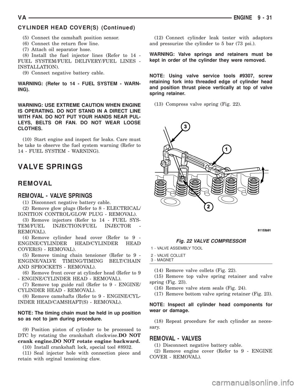
(13) Compress valve spring (Fig. 22).
(14) Remove valve collets (Fig. 22).
(15) Remove top valve spring retainer and valve
spring (Fig. 23).
(16) Remove valve stem seals (Fig. 24).
(17) Remove bottom valve spring retainer (Fig. 23).
NOTE: Inspect all cylinder head components for
wear or damage.
(18) Repeat procedure for each cylinder as neces-
sary.
REMOVAL - VALVES
(1) Disconnect negative battery cable.
(2) Remove engine cover (Refer to 9 - ENGINE
COVER - REMOVAL).
Fig. 22 VALVE COMPRESSOR
1 - VALVE ASSEMBLY TOOL
2 - VALVE COLLET
3 - MAGNET
VAENGINE 9 - 31
CYLINDER HEAD COVER(S) (Continued)
Page 771 of 1232
(10) Position piston of #1 cylinder to ignition TDC.
(11) Install camshafts and check basic position
(Refer to 9 - ENGINE/CYLINDER HEAD/CAM-
SHAFT(S) - INSTALLATION).
(12) Install top guide rail (Refer to 9 - ENGINE/
CYLINDER HEAD - INSTALLATION).
(13) Install front cover at cylinder head (Refer to 9
- ENGINE/CYLINDER HEAD - INSTALLATION).
(14) Install timing chain tensioner with new gas-
ket (Refer to 9 - ENGINE/VALVE TIMING/TIMING
BELT/CHAIN AND SPROCKETS - INSTALLATION)
(15) Install cylinder head cover (Refer to 9 -
ENGINE/CYLINDER HEAD/CYLINDER HEAD
COVER(S) - INSTALLATION).
(16) Install glow plugs (Refer to 8 - ELECTRICAL/
IGNITION CONTROL/GLOW PLUG - INSTALLA-
TION).
WARNING: SERVICE VEHICLES IN A WELL VENTI-
LATED AREA AND AVOID IGNITION SORCES. RISK
OF INJURY TO SKIN AND EYES FROM FUEL JET
FLOWING OUT.
(17) Install injectors (Refer to 14 - FUEL SYS-
TEM/FUEL INJECTION/FUEL INJECTOR -
INSTALLATION).
(18) Reconnect negative battery cable.
WARNING: USE EXTREME CAUTION WHEN THE
ENGINE IS OPERATING. DO NOT STAND IN ADIRECT LINE WITH THE FAN. DO NOT PUT YOUR
HANDS NEAR THE PULLEYS, BELTS OR FAN. DO
NOT WEAR LOOSE CLOTHING.
(19) Start the engine and inspect for leaks.Care
must be taken to observe the fuel system warning
(Refer to 14 - FUEL SYSTEM - WARNING)
(20) Install engine cover (Refer to 9 - ENGINE
COVER - INSTALLATION).
INSTALLATION - VALVES
WARNING: Valves must be kept in their original
positions in cylinder head. Failure to do so will
result in engine damage.
NOTE: Inspect all valves, springs and retainers for
wear or damage. Replace as necessary.
(1) Install valves in their original position in the
cylinder head.
(2) Install lower valve spring retainer.
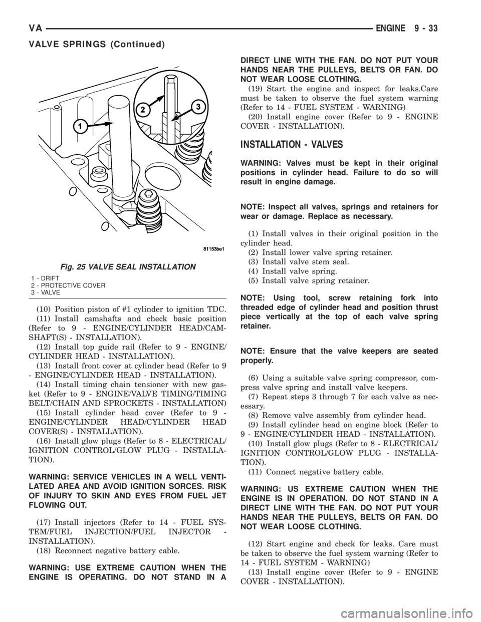
(3) Install valve stem seal.
(4) Install valve spring.
(5) Install valve spring retainer.
NOTE: Using tool, screw retaining fork into
threaded edge of cylinder head and position thrust
piece vertically at the top of each valve spring
retainer.
NOTE: Ensure that the valve keepers are seated
properly.
(6) Using a suitable valve spring compressor, com-
press valve spring and install valve keepers.
(7) Repeat steps 3 through 7 for each valve as nec-
essary.
(8) Remove valve assembly from cylinder head.
(9) Install cylinder head on engine block (Refer to
9 - ENGINE/CYLINDER HEAD - INSTALLATION).
(10) Install glow plugs (Refer to 8 - ELECTRICAL/
IGNITION CONTROL/GLOW PLUG - INSTALLA-
TION).
(11) Connect negative battery cable.
WARNING: US EXTREME CAUTION WHEN THE
ENGINE IS IN OPERATION. DO NOT STAND IN A
DIRECT LINE WITH THE FAN. DO NOT PUT YOUR
HANDS NEAR THE PULLEYS, BELTS OR FAN. DO
NOT WEAR LOOSE CLOTHING.
(12) Start engine and check for leaks. Care must
be taken to observe the fuel system warning (Refer to
14 - FUEL SYSTEM - WARNING)
(13) Install engine cover (Refer to 9 - ENGINE
COVER - INSTALLATION).
Fig. 25 VALVE SEAL INSTALLATION
1 - DRIFT
2 - PROTECTIVE COVER
3 - VALVE
VAENGINE 9 - 33
VALVE SPRINGS (Continued)
Page 772 of 1232
ENGINE BLOCK
STANDARD PROCEDURE
STANDARD PROCEDURE - REPLACING ENGINE
CORE AND OIL GALLERY PLUGS
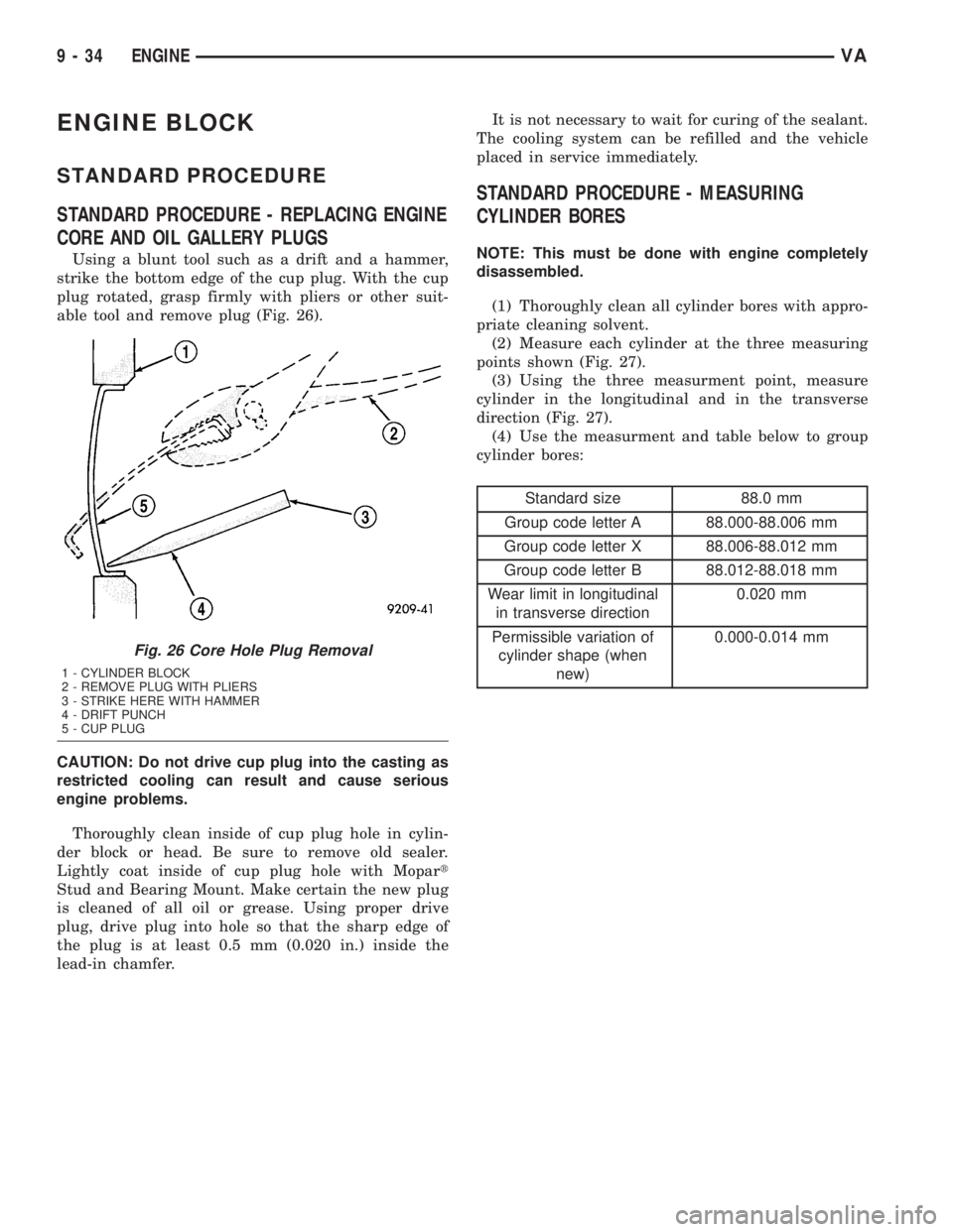
Using a blunt tool such as a drift and a hammer,
strike the bottom edge of the cup plug. With the cup
plug rotated, grasp firmly with pliers or other suit-
able tool and remove plug (Fig. 26).
CAUTION: Do not drive cup plug into the casting as
restricted cooling can result and cause serious
engine problems.
Thoroughly clean inside of cup plug hole in cylin-
der block or head. Be sure to remove old sealer.
Lightly coat inside of cup plug hole with Mopart
Stud and Bearing Mount. Make certain the new plug
is cleaned of all oil or grease. Using proper drive
plug, drive plug into hole so that the sharp edge of
the plug is at least 0.5 mm (0.020 in.) inside the
lead-in chamfer.It is not necessary to wait for curing of the sealant.
The cooling system can be refilled and the vehicle
placed in service immediately.
STANDARD PROCEDURE - MEASURING
CYLINDER BORES
NOTE: This must be done with engine completely
disassembled.
(1) Thoroughly clean all cylinder bores with appro-
priate cleaning solvent.
(2) Measure each cylinder at the three measuring
points shown (Fig. 27).
(3) Using the three measurment point, measure
cylinder in the longitudinal and in the transverse
direction (Fig. 27).
(4) Use the measurment and table below to group
cylinder bores:
Standard size 88.0 mm
Group code letter A 88.000-88.006 mm
Group code letter X 88.006-88.012 mm
Group code letter B 88.012-88.018 mm
Wear limit in longitudinal
in transverse direction0.020 mm
Permissible variation of
cylinder shape (when
new)0.000-0.014 mm
Fig. 26 Core Hole Plug Removal
1 - CYLINDER BLOCK
2 - REMOVE PLUG WITH PLIERS
3 - STRIKE HERE WITH HAMMER
4 - DRIFT PUNCH
5 - CUP PLUG
9 - 34 ENGINEVA
Page 899 of 1232
DIAGNOSIS AND TESTING
DIAGNOSIS AND TESTING - AUTOMATIC
TRANSMISSION
CAUTION: Before attempting any repair on a NAG1
automatic transmission, check for Diagnostic Trou-
ble Codes with the DRBTscan tool.
Transmission malfunctions may be caused by these
general conditions:
²Poor engine performance.
²Improper adjustments.
²Hydraulic malfunctions.
²Mechanical malfunctions.
²Electronic malfunctions.
²Transfer case performance.
Diagnosis of these problems should always begin
by checking the easily accessible variables: fluid level
and condition, gearshift cable adjustment. Then per-
form a road test to determine if the problem has been
corrected or if more diagnosis is necessary.
DIAGNOSIS AND TESTING - PRELIMINARY
Two basic procedures are required. One procedure
for vehicles that are drivable and an alternate proce-
dure for disabled vehicles (will not back up or move
forward).
VEHICLE IS DRIVABLE
(1) Check for transmission fault codes using DRBt
scan tool.
(2) Check fluid level and condition.
(3) Adjust gearshift cable if complaint was based
on delayed, erratic, or harsh shifts.
(4) Road test and note how transmission upshifts,
downshifts, and engages.
VEHICLE IS DISABLED
(1) Check fluid level and condition.(2) Check for broken or disconnected gearshift
cable.
(3) Check for cracked, leaking cooler lines, or loose
or missing pressure-port plugs.
(4) Raise and support vehicle on safety stands,
start engine, shift transmission into gear, and note
following:
(a) If propeller shaft turns but wheels do not,
problem is with differential or axle shafts.
(b) If propeller shaft does not turn and transmis-
sion is noisy, stop engine. Remove oil pan, and
check for debris. If pan is clear, remove transmis-
sion and check for damaged driveplate, converter,
oil pump, or input shaft.
(c) If propeller shaft does not turn and transmis-
sion is not noisy, perform hydraulic-pressure test to
determine if problem is hydraulic or mechanical.
DIAGNOSIS AND TESTING - ROAD TESTING
Before road testing, be sure the fluid level and con-
trol cable adjustments have been checked and
adjusted if necessary. Verify that all diagnostic trou-
ble codes have been resolved.
Observe engine performance during the road test.
A poorly tuned engine will not allow accurate analy-
sis of transmission operation.
Operate the transmission in all gear ranges. Check
for shift variations and engine flare which indicates
slippage. Note if shifts are harsh, spongy, delayed,
early, or if part throttle downshifts are sensitive.
Slippage indicated by engine flare, usually means
clutch, overrunning clutch, or line pressure problems.
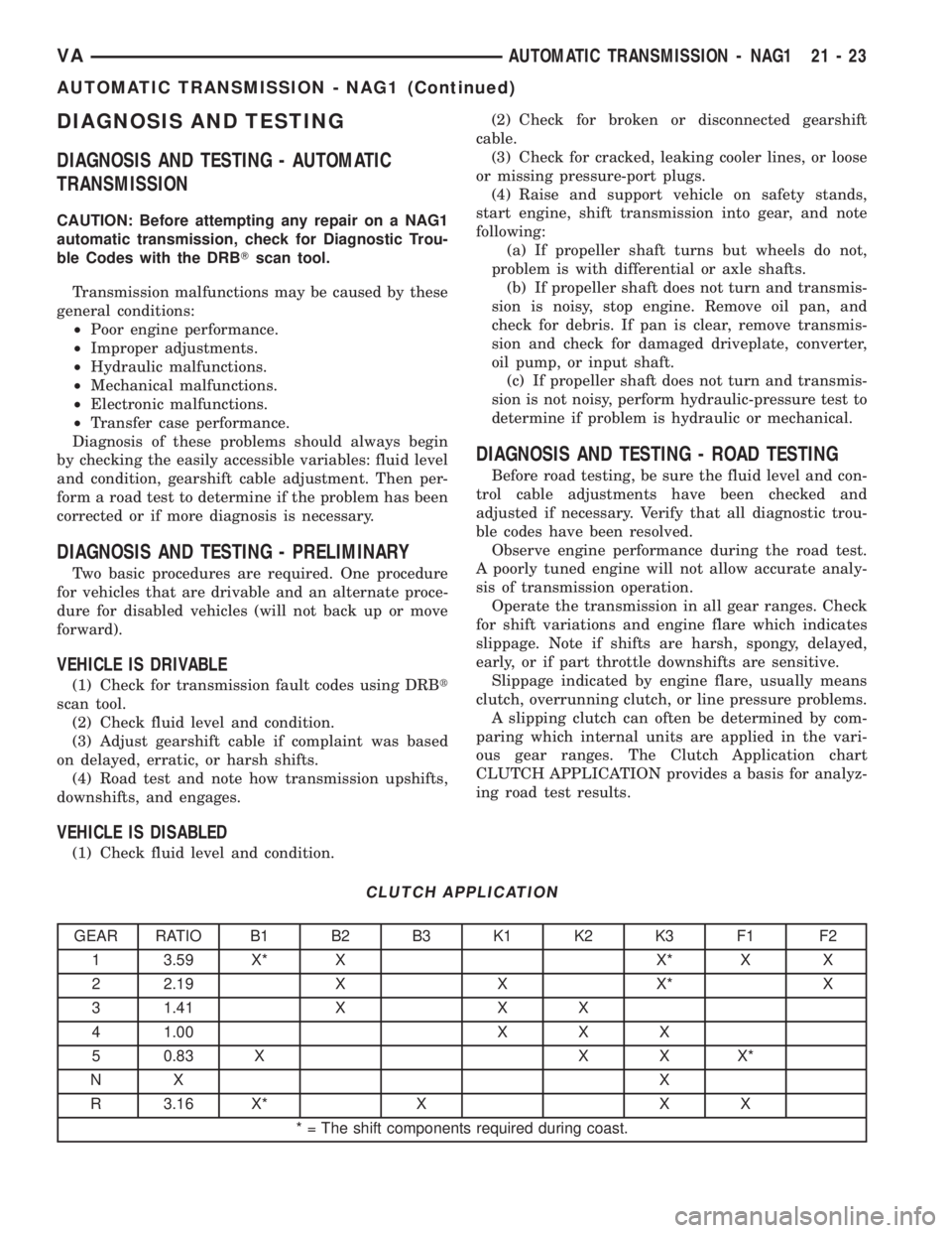
A slipping clutch can often be determined by com-
paring which internal units are applied in the vari-
ous gear ranges. The Clutch Application chart
CLUTCH APPLICATION provides a basis for analyz-
ing road test results.
CLUTCH APPLICATION
GEAR RATIO B1 B2 B3 K1 K2 K3 F1 F2
1 3.59 X* X X* X X
2 2.19 X X X* X
3 1.41 X X X
4 1.00 X X X
5 0.83 X X X X*
NX X
R 3.16 X* X X X
* = The shift components required during coast.
VAAUTOMATIC TRANSMISSION - NAG1 21 - 23
AUTOMATIC TRANSMISSION - NAG1 (Continued)
Page 1039 of 1232
BODY
TABLE OF CONTENTS
page page
BODY
WARNING
SAFETY PRECAUTIONS AND WARNINGS . . . 1
DIAGNOSIS AND TESTING
DIAGNOSIS AND TESTING - WATER LEAKS . 1
DIAGNOSIS AND TESTING - WIND NOISE . . . 2
STANDARD PROCEDURE
STANDARD PROCEDURE - PLASTIC BODY
PANEL REPAIR........................3
STANDARD PROCEDURE - BUZZ, SQUEAK
& RATTLE...........................10
SPECIFICATIONS.......................12DOOR - FRONT.........................13
DOORS - REAR.........................24
DOORS - SLIDING.......................36
EXTERIOR.............................47
HOOD.................................50
INSTRUMENT PANEL.....................53
INTERIOR..............................67
PAINT.................................74
SEATS................................76
STATIONARY GLASS.....................81
WEATHERSTRIP/SEALS...................87
BODY STRUCTURE......................88
BODY
WARNING
SAFETY PRECAUTIONS AND WARNINGS
WARNING: USE AN OSHA APPROVED BREATHING
FILTER WHEN SPRAYING PAINT OR SOLVENTS IN
A CONFINED AREA. PERSONAL INJURY CAN
RESULT.
²AVOID PROLONGED SKIN CONTACT WITH
PETROLEUM OR ALCOHOL ± BASED CLEANING
SOLVENTS. PERSONAL INJURY CAN RESULT.
²DO NOT STAND UNDER A HOISTED VEHICLE
THAT IS NOT PROPERLY SUPPORTED ON SAFETY
STANDS. PERSONAL INJURY CAN RESULT.
CAUTION: When holes must be drilled or punched
in an inner body panel, verify depth of space to the
outer body panel, electrical wiring, or other compo-
nents. Damage to vehicle can result.
²Do not weld exterior panels unless combustible
material on the interior of vehicle is removed from
the repair area. Fire or hazardous conditions, can
result.
²Always have a fire extinguisher ready for use
when welding.
²Disconnect the negative (-) cable clamp from
the battery when servicing electrical components
that are live when the ignition is OFF. Damage to
electrical system can result.
²Do not use abrasive chemicals or compounds
on painted surfaces. Damage to finish can result.²Do not use harsh alkaline based cleaning sol-
vents on painted or upholstered surfaces. Damage
to finish or color can result.
²Do not hammer or pound on plastic trim panel
when servicing interior trim. Plastic panels can
break.DIAGNOSIS AND TESTING
DIAGNOSIS AND TESTING - WATER LEAKS
Water leaks can be caused by poor sealing,
improper body component alignment, body seam
porosity, missing plugs, or blocked drain holes. Cen-
trifugal and gravitational force can cause water to
drip from a location away from the actual leak point,
making leak detection difficult. All body sealing
points should be water tight in normal wet-driving
conditions. Water flowing downward from the front of
the vehicle should not enter the passenger or luggage
compartment. Moving sealing surfaces will not
always seal water tight under all conditions. At
times, side glass or door seals will allow water to
enter the passenger compartment during high pres-
sure washing or hard driving rain (severe) condi-
tions. Overcompensating on door or glass
adjustments to stop a water leak that occurs under
severe conditions can cause premature seal wear and
excessive closing or latching effort. After completing
a repair, water test vehicle to verify leak has stopped
before returning vehicle to use.
VABODY 23 - 1
Page 1040 of 1232
VISUAL INSPECTION BEFORE WATER LEAK TESTS
Verify that floor and body plugs are in place, body
drains are clear, and body components are properly
aligned and sealed. If component alignment or seal-
ing is necessary, refer to the appropriate section of
this group for proper procedures.
WATER LEAK TESTS
WARNING: DO NOT USE ELECTRIC SHOP LIGHTS
OR TOOLS IN WATER TEST AREA. PERSONAL
INJURY CAN RESULT.
When the conditions causing a water leak have
been determined, simulate the conditions as closely
as possible.
²If a leak occurs with the vehicle parked in a
steady light rain, flood the leak area with an open-
ended garden hose.
²If a leak occurs while driving at highway speeds
in a steady rain, test the leak area with a reasonable
velocity stream or fan spray of water. Direct the
spray in a direction comparable to actual conditions.
²If a leak occurs when the vehicle is parked on an
incline, hoist the end or side of the vehicle to simu-
late this condition. This method can be used when
the leak occurs when the vehicle accelerates, stops or
turns. If the leak occurs on acceleration, hoist the
front of the vehicle. If the leak occurs when braking,
hoist the back of the vehicle. If the leak occurs on left
turns, hoist the left side of the vehicle. If the leak
occurs on right turns, hoist the right side of the vehi-
cle. For hoisting recommendations (Refer to LUBRI-
CATION & MAINTENANCE/HOISTING -
STANDARD PROCEDURE).
WATER LEAK DETECTION
To detect a water leak point-of-entry, do a water
test and watch for water tracks or droplets forming
on the inside of the vehicle. If necessary, remove inte-
rior trim covers or panels to gain visual access to the
leak area. If the hose cannot be positioned without
being held, have someone help do the water test.
Some water leaks must be tested for a considerable
length of time to become apparent. When a leak
appears, find the highest point of the water track or
drop. The highest point usually will show the point of
entry. After leak point has been found, repair the
leak and water test to verify that the leak has
stopped.
Locating the entry point of water that is leaking
into a cavity between panels can be difficult. The
trapped water may splash or run from the cavity,
often at a distance from the entry point. Most water
leaks of this type become apparent after accelerating,
stopping, turning, or when on an incline.MIRROR INSPECTION METHOD
When a leak point area is visually obstructed, use
a suitable mirror to gain visual access. A mirror can
also be used to deflect light to a limited-access area
to assist in locating a leak point.
BRIGHT LIGHT LEAK TEST METHOD
Some water leaks in the luggage compartment can
be detected without water testing. Position the vehi-
cle in a brightly lit area. From inside the darkened
luggage compartment inspect around seals and body
seams. If necessary, have a helper direct a drop light
over the suspected leak areas around the luggage
compartment. If light is visible through a normally
sealed location, water could enter through the open-
ing.
PRESSURIZED LEAK TEST METHOD
When a water leak into the passenger compart-
ment cannot be detected by water testing, pressurize
the passenger compartment and soap test exterior of
the vehicle. To pressurize the passenger compart-
ment, close all doors and windows, start engine, and
set heater control to high blower in HEAT position. If
engine can not be started, connect a charger to the
battery to ensure adequate voltage to the blower.
With interior pressurized, apply dish detergent solu-
tion to suspected leak area on the exterior of the
vehicle. Apply detergent solution with spray device or
soft bristle brush. If soap bubbles occur at a body
seam, joint, seal or gasket, the leak entry point could
be at that location.
DIAGNOSIS AND TESTING - WIND NOISE
Wind noise is the result of most air leaks. Air leaks
can be caused by poor sealing, improper body compo-
nent alignment, body seam porosity, or missing plugs
in the engine compartment or door hinge pillar areas.
All body sealing points should be airtight in normal
driving conditions. Moving sealing surfaces will not
always seal airtight under all conditions. At times,
side glass or door seals will allow wind noise to be
noticed in the passenger compartment during high
cross winds. Over compensating on door or glass
adjustments to stop wind noise that occurs under
severe conditions can cause premature seal wear and
excessive closing or latching effort. After a repair pro-
cedure has been performed, test vehicle to verify
noise has stopped before returning vehicle to use.
VISUAL INSPECTION BEFORE TESTS
Verify that floor and body plugs are in place and
body components are aligned and sealed. If compo-
nent alignment or sealing is necessary, refer to the
appropriate section of this group for proper proce-
dures.
23 - 2 BODYVA
BODY (Continued)
Page 1041 of 1232
ROAD TESTING WIND NOISE
(1) Drive the vehicle to verify the general location
of the wind noise.
(2) Apply 50 mm (2 in.) masking tape in 150 mm
(6 in.) lengths along weatherstrips, weld seams or
moldings. After each length is applied, drive the vehi-
cle. If noise goes away after a piece of tape is applied,
remove tape, locate, and repair defect.
POSSIBLE CAUSE OF WIND NOISE
²Moldings standing away from body surface can
catch wind and whistle.
²Gaps in sealed areas behind overhanging body
flanges can cause wind-rushing sounds.
²Misaligned movable components.
²Missing or improperly installed plugs in pillars.
²Weld burn through holes.
STANDARD PROCEDURE
STANDARD PROCEDURE - PLASTIC BODY
PANEL REPAIR
There are many different types of plastics used in
today's automotive environment. We group plastics in
three different categories: Rigid, Semi-Rigid, and
Flexible. Any of these plastics may require the use of
an adhesion promoter for repair. These types of plas-
tic are used extensively on DaimlerChrysler Motors
vehicles. Always follow repair material manufactur-
er's plastic identification and repair procedures.
Rigid Plastics:
Examples of rigid plastic use: Fascias, Hoods,
Doors, and other Body Panels, which include SMC,
ABS, and Polycarbonates.
Semi-Rigid Plastics:
Examples of semi-rigid plastic use: Interior Panels,
Under Hood Panels, and other Body Trim Panels.
Flexible Plastics:
Examples of flexible plastic use: Fascias, Body
Moldings, and upper and lower Fascia Covers.
Repair Procedure:
The repair procedure for all three categories of
plastics is basically the same. The one difference is
the material used for the repair. The materials must
be specific for each substrate, rigid repair material
for rigid plastic repair, semi-rigid repair material for
semi-rigid plastic repair and flexible repair material
for flexible plastic repair.
Adhesion Promoter/Surface Modifier:
Adhesion Promoters/Surface Modifiers are required
for certain plastics. All three categories may have
plastics that require the use of adhesion promoter/
surface modifiers. Always follow repair material man-
ufacturer's plastic identification and repair
procedures.
SAFETY PRECAUTION AND WARNINGS
WARNING:
²EYE PROTECTION SHOULD BE USED WHEN
SERVICING COMPONENTS. PERSONAL INJURY
CAN RESULT.
²USE AN OSHA APPROVED BREATHING MASK
WHEN MIXING EPOXY, GRINDING, AND SPRAYING
PAINT OR SOLVENTS IN A CONFINED AREA. PER-
SONAL INJURY CAN RESULT.
²AVOID PROLONGED SKIN CONTACT WITH
RESIN, PETROLEUM, OR ALCOHOL BASED SOL-
VENTS. PERSONAL INJURY CAN RESULT.
²DO NOT VENTURE UNDER A HOISTED VEHI-
CLE THAT IS NOT PROPERLY SUPPORTED ON
SAFETY STANDS. PERSONAL INJURY CAN
RESULT.
NOTE:
²When holes must be drilled or cut in body pan-
els, verify locations of internal body components
and electrical wiring. Damage to vehicle can result.
²Do not use abrasive chemicals or compounds
on undamaged painted surfaces around repair
areas. Damage to finish can result.
VABODY 23 - 3
BODY (Continued)
Page 1076 of 1232
INSTALLATION
(1) Position roller arm in guide track.
(2) Install arm into door opening and line up tab
with marks made previously.
(3) Install bolt and tighten to 45 N´m (33 ft. lbs.).
(4) Install rubber cover.
(5) Adjust door if necessary. (Refer to 23 - BODY/
DOORS - SLIDING/SLIDING DOOR - ADJUST-
MENTS)
(6) Install trim panel if necessary. (Refer to 23 -
BODY/DOORS - SLIDING/TRIM PANEL - INSTAL-
LATION)
(7) Install trim cover.
LOWER ROLLER ARM
REMOVAL
(1) Remove trim plugs and screws and remove
stepwell scuff pad. (Fig. 5)
(2) Remove the door screws and remove the roller
arm. (Fig. 6)
INSTALLATION
(1) Install roller arm and install door screws.
(2) Tighten screws to 25 N´m (18 ft. lbs.).
(3) Install stepwell scuff pad and install screws.
(4) Adjust door if necessary. (Refer to 23 - BODY/
DOORS - SLIDING/SLIDING DOOR - ADJUST-
MENTS)
CENTER TRACK
REMOVAL
(1) Remove center roller arm. (Refer to 23 - BODY/
DOORS - SLIDING/CENTER ROLLER ARM -
REMOVAL)
(2) Remove quarter trim panel. (Refer to 23 -
BODY/INTERIOR/QUARTER TRIM PANEL -
REMOVAL)
(3) Remove the nuts. (Fig. 7)
(4) Remove the front bolts.
Fig. 7 SLIDING DOOR CENTER TRACK
1 - NUTS
2 - QUARTER TRIM PANEL
3 - BOLT
4 - BOLT
5 - CENTER TRACK
Fig. 5 SLIDING DOOR SCUFF PAD
1 - TRIM PLUGS
2 - SCREWS (5)
3 - SCUFF PAD
Fig. 6 SLIDING DOOR LOWER ROLLER ARM
1 - SCREWS
2 - ROLLER ARM
23 - 38 DOORS - SLIDINGVA
CENTER ROLLER ARM (Continued)