2005 MERCEDES-BENZ SPRINTER seats
[x] Cancel search: seatsPage 161 of 1232
HEATED SYSTEMS
TABLE OF CONTENTS
page page
HEATED SEATS
DESCRIPTION..........................1
OPERATION............................2
DIAGNOSIS AND TESTING - HEATED SEATS . . 2
DRIVER HEATED SEAT SWITCH
DESCRIPTION..........................2
OPERATION............................2
DIAGNOSIS AND TESTING - DRIVER HEATED
SEAT SWITCH.........................2
REMOVAL.............................3
INSTALLATION..........................3
HEATED SEAT ELEMENT
DESCRIPTION..........................3
OPERATION............................3
DIAGNOSIS AND TESTING - HEATED SEAT
ELEMENT............................3
HEATED SEAT RELAY
DESCRIPTION..........................4OPERATION............................4
DIAGNOSIS AND TESTING - HEATED SEAT
RELAY...............................4
REMOVAL.............................4
INSTALLATION..........................4
HEATED SEAT SENSOR
DESCRIPTION..........................4
DIAGNOSIS AND TESTING - HEATED SEAT
SENSOR.............................4
PASSENGER HEATED SEAT SWITCH
DESCRIPTION..........................5
OPERATION............................5
DIAGNOSIS AND TESTING - PASSENGER
HEATED SEAT SWITCH.................5
REMOVAL.............................5
INSTALLATION..........................5
HEATED SEATS
DESCRIPTION
Individually controlled, electrically heated front
seats are available factory-installed optional equip-
ment on this model. Vehicles with this option can be
visually identified by the two separate heated seat
switches mounted in the instrument panel. The
heated seat system allows the front seat driver and
passenger to select from two different levels of sup-
plemental electrical seat heating, or no seat heating
to suit their individual comfort requirements. The
heated seat system for this vehicle includes the fol-
lowing major components, which are described in fur-
ther detail later in this section:
²Heated Seat Elements- Four heated seat ele-
ments are used per vehicle, two for each front seat.
One heating element in the seat back and one in the
seat cushion. The heated seat sensor is integral to
the seat cushion heating element. The heated seat
elements are integral to the front seat and seat back
cushions. Refer to heated seat elements later in this
section for additional information.²Heated Seat Relay- One heated seat relay is
used per vehicle. The relay is located in the fuse
block and is responsible for distributing the voltage
(B+) to the heated seat elements.
²Heated Seat Sensors- Two heated seat sen-
sors are used per vehicle, one for each front seat. The
heated seat sensors are integral to each of the heated
seat element assemblies. Refer to heated seat sensor
later in this section for additional information.
²Heated Seat Switches- Two heated seat
switches are used per vehicle, one for each front seat.
The switches are mounted in the instrument panel.
Refer to heated seat switches later in this section for
additional information.
Hard wired circuitry connects the heated seat sys-
tem components to each other through the electrical
system of the vehicle. Refer to Wiring for additional
information. The wiring information includes wiring
diagrams, proper wire and connector repair proce-
dures, further details on wire harness routing and
retention, as well as pin-out and location views for
the various wire harness connectors, splices and
grounds.
VAHEATED SYSTEMS 8G - 1
Page 162 of 1232
OPERATION
The heated seat system is designed to provide indi-
vidually controlled, supplemental heat to the seat
cushion and seat back surfaces of both front seats.
Because this system converts electrical current to
heat, the heated seat system can provide a measure
of warm comfort almost immediately upon entering a
cold vehicle, rather than having to wait for the
engine coolant to reach sufficient temperature to
deliver heat through the conventional heater system.
This system allows each front seat occupant to indi-
vidually select one of two comfort levels, Hi or Lo, or
to turn the heater for their seat off.
The heated seat system components operate on
battery current received through a fuse in the Fuse
Block on a fused ignition switch output (run-acc) cir-
cuit so that the system will only operate when theignition switch is in the On or Accessory positions.
The heated seat system will be turned Off automati-
cally whenever the ignition switch is turned to any
position except On or Accessory. Also, the heated seat
system will not operate when the surface tempera-
ture of the seat cushion cover at either heated seat
sensor is above the designed temperature set points
of the system.
DIAGNOSIS AND TESTING - HEATED SEATS
Refer toWiringfor the appropriate wiring infor-
mation. The wiring information includes wiring dia-
grams, proper wire and connector repair procedures,
further details on wire harness routing and reten-
tion, as well as pin-out and location views for the
various wire harness connectors, splices and grounds.
HEATED SEAT SYSTEM DIAGNOSIS
CONDITION POSSIBLE CAUSES CORRECTION
NO HEATED SEAT SWITCH
ILLUMINATION WITH
IGNITION ON1. Faulty fuse. 1. Check heated seat fuse in Fuse Block.
Replace fuse, if required.
2. Wiring faulty. 2. Check fused ignition switch output (run-acc)
circuit from heated seat switch connector to
ignition switch. Repair, if required.
3. Ground faulty. 3. Check for ground at heated seat switch
connector. Repair, if required.
4. Faulty switch. 4. Refer to Heated Seat Switch for the proper
switch diagnosis and testing procedures.
DRIVER HEATED SEAT
SWITCH
DESCRIPTION
The heated seat switches are located on the instru-
ment panel, in the accessory switch bezel. The two,
momentary rocker type switches provide a signal to
the Heated Seat Relay through separate hard wired
circuits. Each switch contains two light emitting
diodes (LED), one for each High and Low setting to
let the occupant know that the seat heater system is
on.
The heated seat switches and their LED's cannot
be repaired. If either switch is faulty or damaged the
entire switch must be replaced.
OPERATION
There are three modes that can be selected with
each of the heated seat switches: Off, Low, and High.
When the top of the switch rocker is depressed, the
low mode is selected and the low mode LED indicator
illuminates. Depressing the top of the switch rocker asecond time will turn the heated seat to Off. This
same process is repeated for High heat setting. The
heated seats will automatically return to the Off
mode anytime the vehicle ignition switch is turned
Off.
Both switches provide separate hard wire inputs to
the Heated Seat Relay to indicate the selected mode.
The Heated Seat Relay responds to the heated seat
switch messages by controlling the output to the seat
heater elements of the selected seat.
DIAGNOSIS AND TESTING - DRIVER HEATED
SEAT SWITCH
For circuit description and diagrams, refer toWir-
ing.
(1) Inspect the Heated Seat Switches for apparent
damage or sticking/binding and replace if required.
Refer to Heated Seat Switch Removal and Installa-
tion in this section.
(2) Replace the heated seat switch with a known
good unit and retest the heated seat system.
8G - 2 HEATED SYSTEMSVA
HEATED SEATS (Continued)
Page 165 of 1232
PASSENGER HEATED SEAT
SWITCH
DESCRIPTION
The heated seat switches are located on the instru-
ment panel, in the accessory switch bezel. The two,
momentary rocker type switches provide a signal to
the Heated Seat Relay through separate hard wired
circuits. Each switch contains two light emitting
diodes (LED), one for each High and Low setting to
let the occupant know that the seat heater system is
on.
The heated seat switches and their LED's cannot
be repaired. If either switch is faulty or damaged the
entire switch must be replaced.
OPERATION
There are three modes that can be selected with
each of the heated seat switches: Off, Low, and High.
When the top of the switch rocker is depressed, the
low mode is selected and the low mode LED indicator
illuminates. Depressing the top of the switch rocker a
second time will turn the heated seat to Off. This
same process is repeated for High heat setting. The
heated seats will automatically return to the Off
mode anytime the vehicle ignition switch is turned
Off.
Both switches provide separate hard wire inputs to
the Heated Seat Relay to indicate the selected mode.
The Heated Seat Relay responds to the heated seat
switch messages by controlling the output to the seat
heater elements of the selected seat.
DIAGNOSIS AND TESTING - PASSENGER
HEATED SEAT SWITCH
For circuit description and diagrams, refer toWir-
ing.
(1) Inspect the Heated Seat Switches for apparent
damage or sticking/binding and replace if required.
Refer to Heated Seat Switch Removal and Installa-
tion in this section.
(2) Replace the heated seat switch with a known
good unit and retest the heated seat system.
REMOVAL
(1) Disconnect and isolate the negative battery
cable.
(2) Remove the gear selector bezel trim. Refer to
the Body section for the procedure.
(3) Remove the storage bin. Refer to the Body sec-
tion for the procedure.
(4) Remove the switch bezel retaining screw and
remove the switch bezel from the instrument panel.
Refer to the Body section for the procedure.
(5) Disconnect electrical connections.
(6) Working from the underside of the switch, gen-
tly rock the switch back and forth out of its mounting
location in the switch bezel.
INSTALLATION
(1) Install the heated seat switch in its mounting
location in the switch bezel.
(2) Connect electrical connections.
(3) Position the switch bezel and install the retain-
ing screw. Refer to the Body section for the proce-
dure.
(4) Install the storage bin. Refer to the Body sec-
tion for the procedure.
(5) Install the gear selector bezel trim. Refer to the
Body section for the procedure.
(6) Connect the negative battery cable.
VAHEATED SYSTEMS 8G - 5
Page 266 of 1232
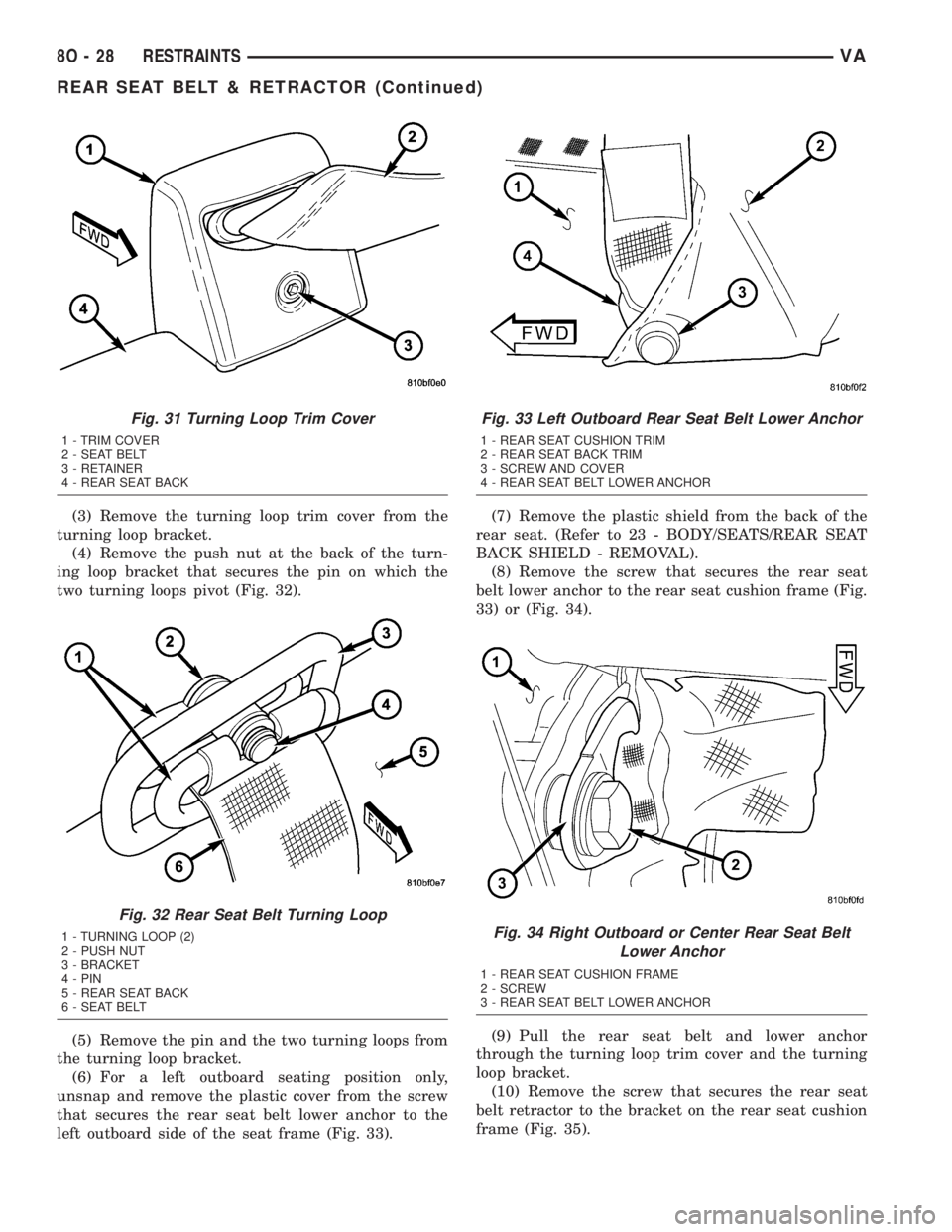
(3) Remove the turning loop trim cover from the
turning loop bracket.
(4) Remove the push nut at the back of the turn-
ing loop bracket that secures the pin on which the
two turning loops pivot (Fig. 32).
(5) Remove the pin and the two turning loops from
the turning loop bracket.
(6) For a left outboard seating position only,
unsnap and remove the plastic cover from the screw
that secures the rear seat belt lower anchor to the
left outboard side of the seat frame (Fig. 33).(7) Remove the plastic shield from the back of the
rear seat. (Refer to 23 - BODY/SEATS/REAR SEAT
BACK SHIELD - REMOVAL).
(8) Remove the screw that secures the rear seat
belt lower anchor to the rear seat cushion frame (Fig.
33) or (Fig. 34).
(9) Pull the rear seat belt and lower anchor
through the turning loop trim cover and the turning
loop bracket.
(10) Remove the screw that secures the rear seat
belt retractor to the bracket on the rear seat cushion
frame (Fig. 35).
Fig. 31 Turning Loop Trim Cover
1 - TRIM COVER
2 - SEAT BELT
3 - RETAINER
4 - REAR SEAT BACK
Fig. 32 Rear Seat Belt Turning Loop
1 - TURNING LOOP (2)
2 - PUSH NUT
3 - BRACKET
4 - PIN
5 - REAR SEAT BACK
6 - SEAT BELT
Fig. 33 Left Outboard Rear Seat Belt Lower Anchor
1 - REAR SEAT CUSHION TRIM
2 - REAR SEAT BACK TRIM
3 - SCREW AND COVER
4 - REAR SEAT BELT LOWER ANCHOR
Fig. 34 Right Outboard or Center Rear Seat Belt
Lower Anchor
1 - REAR SEAT CUSHION FRAME
2 - SCREW
3 - REAR SEAT BELT LOWER ANCHOR
8O - 28 RESTRAINTSVA
REAR SEAT BELT & RETRACTOR (Continued)
Page 267 of 1232
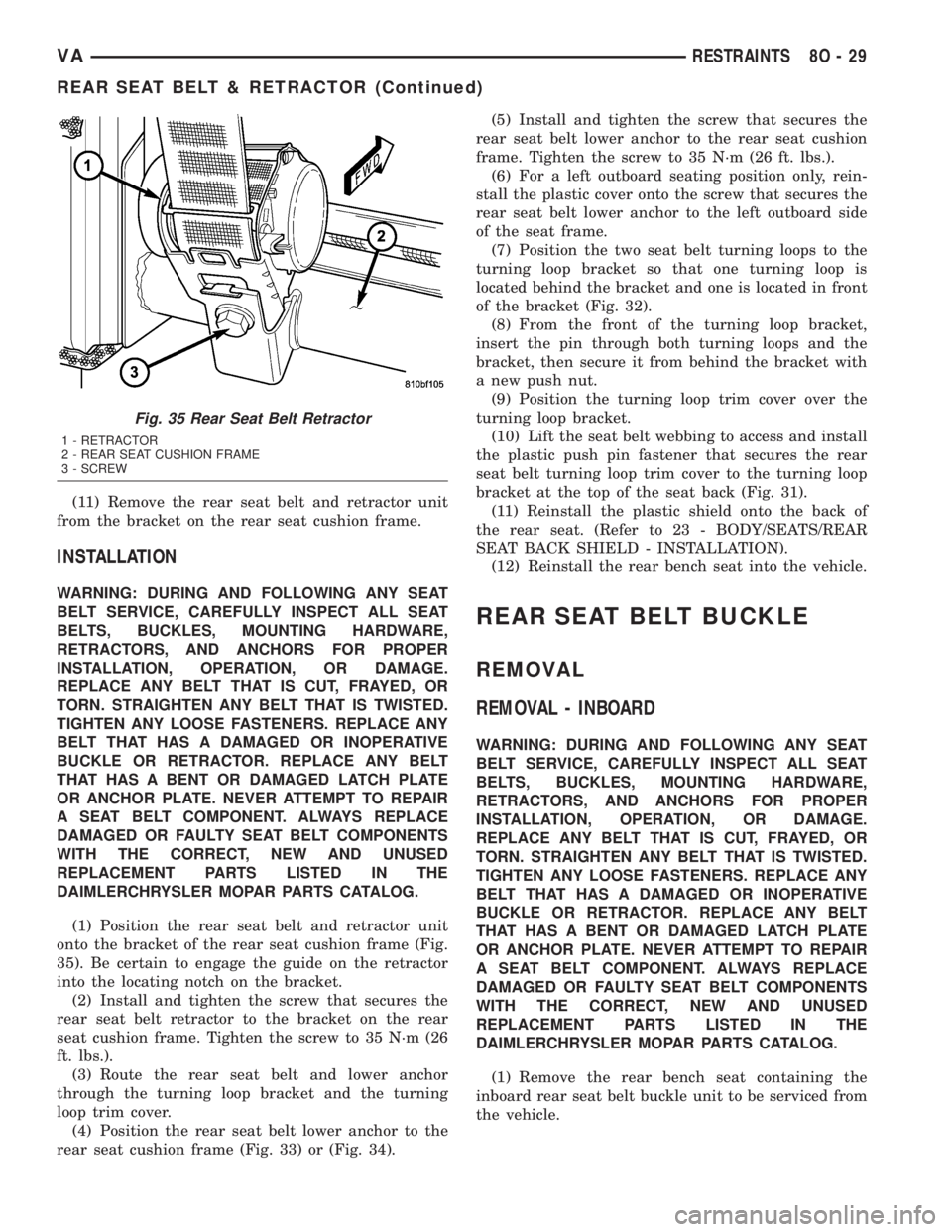
(11) Remove the rear seat belt and retractor unit
from the bracket on the rear seat cushion frame.
INSTALLATION
WARNING: DURING AND FOLLOWING ANY SEAT
BELT SERVICE, CAREFULLY INSPECT ALL SEAT
BELTS, BUCKLES, MOUNTING HARDWARE,
RETRACTORS, AND ANCHORS FOR PROPER
INSTALLATION, OPERATION, OR DAMAGE.
REPLACE ANY BELT THAT IS CUT, FRAYED, OR
TORN. STRAIGHTEN ANY BELT THAT IS TWISTED.
TIGHTEN ANY LOOSE FASTENERS. REPLACE ANY
BELT THAT HAS A DAMAGED OR INOPERATIVE
BUCKLE OR RETRACTOR. REPLACE ANY BELT
THAT HAS A BENT OR DAMAGED LATCH PLATE
OR ANCHOR PLATE. NEVER ATTEMPT TO REPAIR
A SEAT BELT COMPONENT. ALWAYS REPLACE
DAMAGED OR FAULTY SEAT BELT COMPONENTS
WITH THE CORRECT, NEW AND UNUSED
REPLACEMENT PARTS LISTED IN THE
DAIMLERCHRYSLER MOPAR PARTS CATALOG.
(1) Position the rear seat belt and retractor unit
onto the bracket of the rear seat cushion frame (Fig.
35). Be certain to engage the guide on the retractor
into the locating notch on the bracket.
(2) Install and tighten the screw that secures the
rear seat belt retractor to the bracket on the rear
seat cushion frame. Tighten the screw to 35 N´m (26
ft. lbs.).
(3) Route the rear seat belt and lower anchor
through the turning loop bracket and the turning
loop trim cover.
(4) Position the rear seat belt lower anchor to the
rear seat cushion frame (Fig. 33) or (Fig. 34).(5) Install and tighten the screw that secures the
rear seat belt lower anchor to the rear seat cushion
frame. Tighten the screw to 35 N´m (26 ft. lbs.).
(6) For a left outboard seating position only, rein-
stall the plastic cover onto the screw that secures the
rear seat belt lower anchor to the left outboard side
of the seat frame.
(7) Position the two seat belt turning loops to the
turning loop bracket so that one turning loop is
located behind the bracket and one is located in front
of the bracket (Fig. 32).
(8) From the front of the turning loop bracket,
insert the pin through both turning loops and the
bracket, then secure it from behind the bracket with
a new push nut.
(9) Position the turning loop trim cover over the
turning loop bracket.
(10) Lift the seat belt webbing to access and install
the plastic push pin fastener that secures the rear
seat belt turning loop trim cover to the turning loop
bracket at the top of the seat back (Fig. 31).
(11) Reinstall the plastic shield onto the back of
the rear seat. (Refer to 23 - BODY/SEATS/REAR
SEAT BACK SHIELD - INSTALLATION).
(12) Reinstall the rear bench seat into the vehicle.
REAR SEAT BELT BUCKLE
REMOVAL
REMOVAL - INBOARD
WARNING: DURING AND FOLLOWING ANY SEAT
BELT SERVICE, CAREFULLY INSPECT ALL SEAT
BELTS, BUCKLES, MOUNTING HARDWARE,
RETRACTORS, AND ANCHORS FOR PROPER
INSTALLATION, OPERATION, OR DAMAGE.
REPLACE ANY BELT THAT IS CUT, FRAYED, OR
TORN. STRAIGHTEN ANY BELT THAT IS TWISTED.
TIGHTEN ANY LOOSE FASTENERS. REPLACE ANY
BELT THAT HAS A DAMAGED OR INOPERATIVE
BUCKLE OR RETRACTOR. REPLACE ANY BELT
THAT HAS A BENT OR DAMAGED LATCH PLATE
OR ANCHOR PLATE. NEVER ATTEMPT TO REPAIR
A SEAT BELT COMPONENT. ALWAYS REPLACE
DAMAGED OR FAULTY SEAT BELT COMPONENTS
WITH THE CORRECT, NEW AND UNUSED
REPLACEMENT PARTS LISTED IN THE
DAIMLERCHRYSLER MOPAR PARTS CATALOG.
(1) Remove the rear bench seat containing the
inboard rear seat belt buckle unit to be serviced from
the vehicle.
Fig. 35 Rear Seat Belt Retractor
1 - RETRACTOR
2 - REAR SEAT CUSHION FRAME
3 - SCREW
VARESTRAINTS 8O - 29
REAR SEAT BELT & RETRACTOR (Continued)
Page 268 of 1232
(2) Remove the plastic shield from the back of the
rear seat. (Refer to 23 - BODY/SEATS/REAR SEAT
BACK SHIELD - REMOVAL).
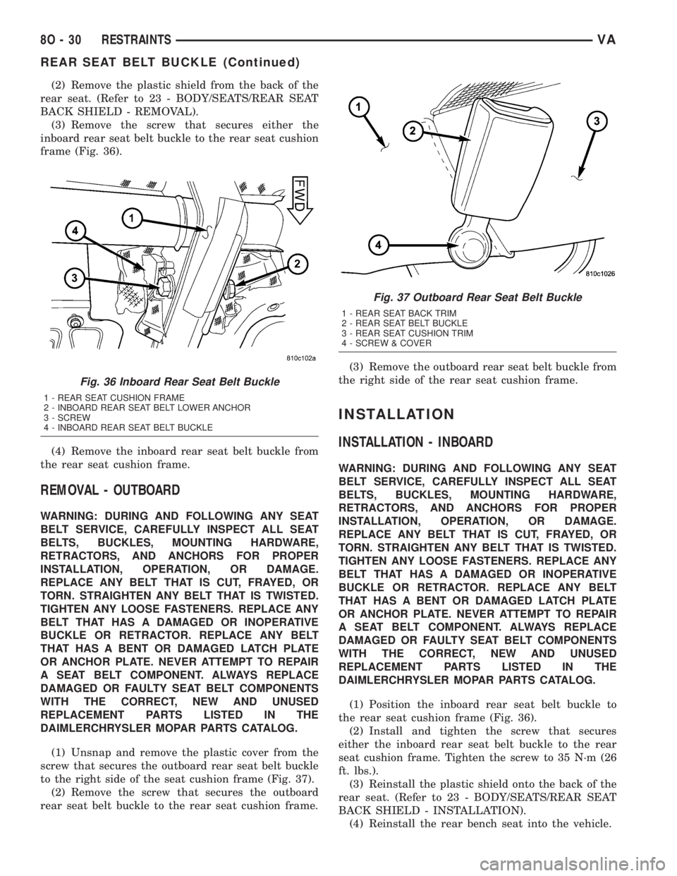
(3) Remove the screw that secures either the
inboard rear seat belt buckle to the rear seat cushion
frame (Fig. 36).
(4) Remove the inboard rear seat belt buckle from
the rear seat cushion frame.
REMOVAL - OUTBOARD
WARNING: DURING AND FOLLOWING ANY SEAT
BELT SERVICE, CAREFULLY INSPECT ALL SEAT
BELTS, BUCKLES, MOUNTING HARDWARE,
RETRACTORS, AND ANCHORS FOR PROPER
INSTALLATION, OPERATION, OR DAMAGE.
REPLACE ANY BELT THAT IS CUT, FRAYED, OR
TORN. STRAIGHTEN ANY BELT THAT IS TWISTED.
TIGHTEN ANY LOOSE FASTENERS. REPLACE ANY
BELT THAT HAS A DAMAGED OR INOPERATIVE
BUCKLE OR RETRACTOR. REPLACE ANY BELT
THAT HAS A BENT OR DAMAGED LATCH PLATE
OR ANCHOR PLATE. NEVER ATTEMPT TO REPAIR
A SEAT BELT COMPONENT. ALWAYS REPLACE
DAMAGED OR FAULTY SEAT BELT COMPONENTS
WITH THE CORRECT, NEW AND UNUSED
REPLACEMENT PARTS LISTED IN THE
DAIMLERCHRYSLER MOPAR PARTS CATALOG.
(1) Unsnap and remove the plastic cover from the
screw that secures the outboard rear seat belt buckle
to the right side of the seat cushion frame (Fig. 37).
(2) Remove the screw that secures the outboard
rear seat belt buckle to the rear seat cushion frame.(3) Remove the outboard rear seat belt buckle from
the right side of the rear seat cushion frame.
INSTALLATION
INSTALLATION - INBOARD
WARNING: DURING AND FOLLOWING ANY SEAT
BELT SERVICE, CAREFULLY INSPECT ALL SEAT
BELTS, BUCKLES, MOUNTING HARDWARE,
RETRACTORS, AND ANCHORS FOR PROPER
INSTALLATION, OPERATION, OR DAMAGE.
REPLACE ANY BELT THAT IS CUT, FRAYED, OR
TORN. STRAIGHTEN ANY BELT THAT IS TWISTED.
TIGHTEN ANY LOOSE FASTENERS. REPLACE ANY
BELT THAT HAS A DAMAGED OR INOPERATIVE
BUCKLE OR RETRACTOR. REPLACE ANY BELT
THAT HAS A BENT OR DAMAGED LATCH PLATE
OR ANCHOR PLATE. NEVER ATTEMPT TO REPAIR
A SEAT BELT COMPONENT. ALWAYS REPLACE
DAMAGED OR FAULTY SEAT BELT COMPONENTS
WITH THE CORRECT, NEW AND UNUSED
REPLACEMENT PARTS LISTED IN THE
DAIMLERCHRYSLER MOPAR PARTS CATALOG.
(1) Position the inboard rear seat belt buckle to
the rear seat cushion frame (Fig. 36).
(2) Install and tighten the screw that secures
either the inboard rear seat belt buckle to the rear
seat cushion frame. Tighten the screw to 35 N´m (26
ft. lbs.).
(3) Reinstall the plastic shield onto the back of the
rear seat. (Refer to 23 - BODY/SEATS/REAR SEAT
BACK SHIELD - INSTALLATION).
(4) Reinstall the rear bench seat into the vehicle.
Fig. 36 Inboard Rear Seat Belt Buckle
1 - REAR SEAT CUSHION FRAME
2 - INBOARD REAR SEAT BELT LOWER ANCHOR
3 - SCREW
4 - INBOARD REAR SEAT BELT BUCKLE
Fig. 37 Outboard Rear Seat Belt Buckle
1 - REAR SEAT BACK TRIM
2 - REAR SEAT BELT BUCKLE
3 - REAR SEAT CUSHION TRIM
4 - SCREW & COVER
8O - 30 RESTRAINTSVA
REAR SEAT BELT BUCKLE (Continued)
Page 289 of 1232
CHECK VALVE
DESCRIPTION
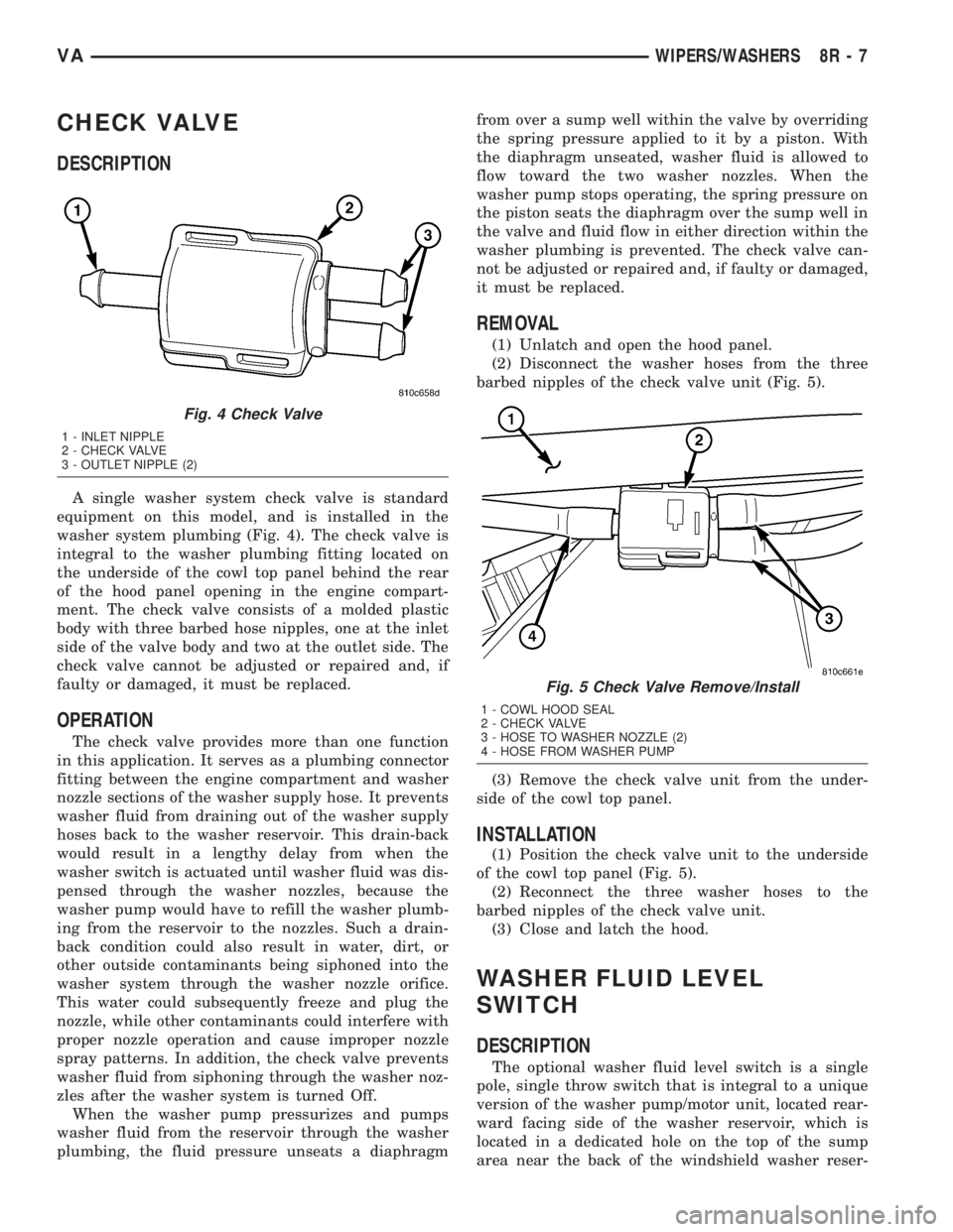
A single washer system check valve is standard
equipment on this model, and is installed in the
washer system plumbing (Fig. 4). The check valve is
integral to the washer plumbing fitting located on
the underside of the cowl top panel behind the rear
of the hood panel opening in the engine compart-
ment. The check valve consists of a molded plastic
body with three barbed hose nipples, one at the inlet
side of the valve body and two at the outlet side. The
check valve cannot be adjusted or repaired and, if
faulty or damaged, it must be replaced.
OPERATION
The check valve provides more than one function
in this application. It serves as a plumbing connector
fitting between the engine compartment and washer
nozzle sections of the washer supply hose. It prevents
washer fluid from draining out of the washer supply
hoses back to the washer reservoir. This drain-back
would result in a lengthy delay from when the
washer switch is actuated until washer fluid was dis-
pensed through the washer nozzles, because the
washer pump would have to refill the washer plumb-
ing from the reservoir to the nozzles. Such a drain-
back condition could also result in water, dirt, or
other outside contaminants being siphoned into the
washer system through the washer nozzle orifice.
This water could subsequently freeze and plug the
nozzle, while other contaminants could interfere with
proper nozzle operation and cause improper nozzle
spray patterns. In addition, the check valve prevents
washer fluid from siphoning through the washer noz-
zles after the washer system is turned Off.
When the washer pump pressurizes and pumps
washer fluid from the reservoir through the washer
plumbing, the fluid pressure unseats a diaphragmfrom over a sump well within the valve by overriding
the spring pressure applied to it by a piston. With
the diaphragm unseated, washer fluid is allowed to
flow toward the two washer nozzles. When the
washer pump stops operating, the spring pressure on
the piston seats the diaphragm over the sump well in
the valve and fluid flow in either direction within the
washer plumbing is prevented. The check valve can-
not be adjusted or repaired and, if faulty or damaged,
it must be replaced.
REMOVAL
(1) Unlatch and open the hood panel.
(2) Disconnect the washer hoses from the three
barbed nipples of the check valve unit (Fig. 5).
(3) Remove the check valve unit from the under-
side of the cowl top panel.
INSTALLATION
(1) Position the check valve unit to the underside
of the cowl top panel (Fig. 5).
(2) Reconnect the three washer hoses to the
barbed nipples of the check valve unit.
(3) Close and latch the hood.
WASHER FLUID LEVEL
SWITCH
DESCRIPTION
The optional washer fluid level switch is a single
pole, single throw switch that is integral to a unique
version of the washer pump/motor unit, located rear-
ward facing side of the washer reservoir, which is
located in a dedicated hole on the top of the sump
area near the back of the windshield washer reser-
Fig. 4 Check Valve
1 - INLET NIPPLE
2 - CHECK VALVE
3 - OUTLET NIPPLE (2)
Fig. 5 Check Valve Remove/Install
1 - COWL HOOD SEAL
2 - CHECK VALVE
3 - HOSE TO WASHER NOZZLE (2)
4 - HOSE FROM WASHER PUMP
VAWIPERS/WASHERS 8R - 7
Page 305 of 1232
WIRING
TABLE OF CONTENTS
page page
WIRING DIAGRAM INFORMATION....... 8W-01-1
COMPONENT INDEX.................. 8W-02-1
POWER DISTRIBUTION............... 8W-10-1
FUSE BLOCK........................ 8W-11-1
GROUND DISTRIBUTION.............. 8W-15-1
BUS COMMUNICATIONS.............. 8W-18-1
CHARGING SYSTEM.................. 8W-20-1
STARTING SYSTEM.................. 8W-21-1
FUEL/IGNITION SYSTEM.............. 8W-30-1
TRANSMISSION CONTROL SYSTEM..... 8W-31-1
VEHICLE SPEED CONTROL............ 8W-33-1
ANTILOCK BRAKES................... 8W-35-1
VEHICLE THEFT SECURITY SYSTEM..... 8W-39-1
INSTRUMENT CLUSTER............... 8W-40-1
HORN/CIGAR LIGHTER................ 8W-41-1
AIR CONDITIONER/HEATER............ 8W-42-1
AIRBAG SYSTEM.................... 8W-43-1
INTERIOR LIGHTING.................. 8W-44-1CENTRAL TIMER MODULE............. 8W-45-1
AUDIO SYSTEM..................... 8W-47-1
REAR WINDOW DEFOGGER............ 8W-48-1
FRONT LIGHTING.................... 8W-50-1
REAR LIGHTING..................... 8W-51-1
TURN SIGNALS...................... 8W-52-1
WIPERS............................ 8W-53-1
TRAILER TOW....................... 8W-54-1
NAVIGATION/TELECOMMUNICATIONS.... 8W-55-1
POWER WINDOWS................... 8W-60-1
POWER DOOR LOCKS................ 8W-61-1
POWER MIRRORS................... 8W-62-1
POWER SEATS...................... 8W-63-1
SPLICE INFORMATION................ 8W-70-1
CONNECTOR PIN-OUTS............... 8W-80-1
CONNECTOR/GROUND/SPLICE
LOCATION........................ 8W-91-1
POWER DISTRIBUTION............... 8W-97-1 VAWIRING 8W - 1