2005 MERCEDES-BENZ SPRINTER wheel bolts
[x] Cancel search: wheel boltsPage 26 of 1232
(2) Install the lower ball joint nut (Fig. 6). Tighten
to 280 N´m (206 ft. lbs.)
(3) Install the strut to the steering knuckle (Fig.
6). Tighten to 185 N´m (136 ft. lbs.).
(4) Install the outer tie rod end to the steering
knuckle (Fig. 6) and tighten the nut to 130 N´m (96
ft. lbs.).
(5) Install the ABS sensor by pushing the sensor
all the way into the knuckle and the sensor will self
adjust when the wheel is turned.
(6) Install the hub/bearing (Refer to 2 - SUSPEN-
SION/FRONT/HUB / BEARING - INSTALLATION).
(7) Install the disc brake caliper adapter with the
brake caliper (Refer to 5 - BRAKES/HYDRAULIC/
MECHANICAL/DISC BRAKE CALIPER ADAPTER -
INSTALLATION).
(8) Install the front wheels (Refer to 22 - TIRES/
WHEELS/WHEELS - INSTALLATION).
(9) Lower the vehicle.
(10) Check and set toe if necessary (Refer to 2 -
SUSPENSION/WHEEL ALIGNMENT - STANDARD
PROCEDURE).
LOWER BALL JOINT
REMOVAL
(1) Raise and support the vehicle.
(2) Remove the front tire and wheel assembly.
(3) Remove the front strut (Refer to 2 - SUSPEN-
SION/FRONT/STRUT - REMOVAL).
(4) Remove the steering knuckle (Refer to 2 - SUS-
PENSION/FRONT/KNUCKLE - REMOVAL).
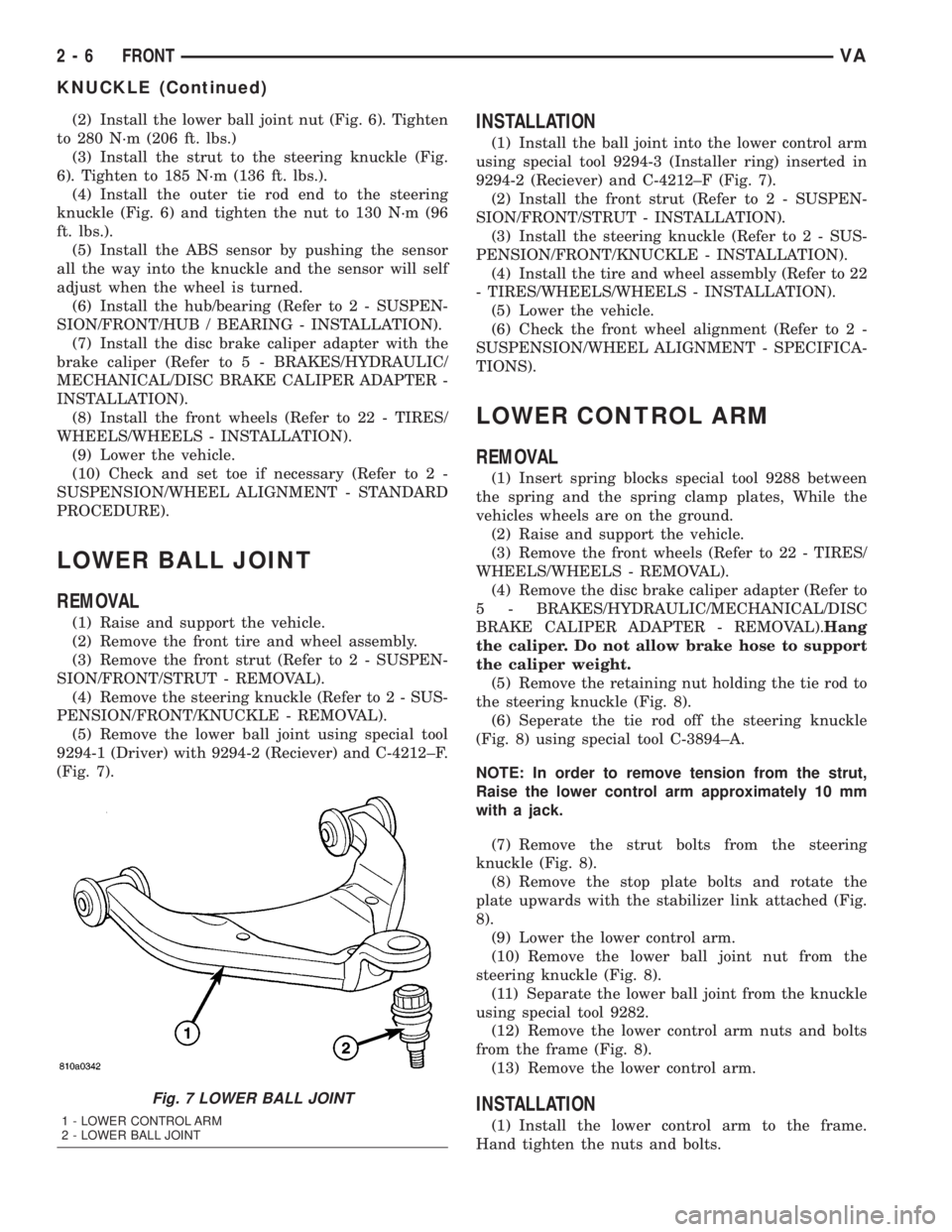
(5) Remove the lower ball joint using special tool
9294-1 (Driver) with 9294-2 (Reciever) and C-4212±F.
(Fig. 7).
INSTALLATION
(1) Install the ball joint into the lower control arm
using special tool 9294-3 (Installer ring) inserted in
9294-2 (Reciever) and C-4212±F (Fig. 7).
(2) Install the front strut (Refer to 2 - SUSPEN-
SION/FRONT/STRUT - INSTALLATION).
(3) Install the steering knuckle (Refer to 2 - SUS-
PENSION/FRONT/KNUCKLE - INSTALLATION).
(4) Install the tire and wheel assembly (Refer to 22
- TIRES/WHEELS/WHEELS - INSTALLATION).
(5) Lower the vehicle.
(6) Check the front wheel alignment (Refer to 2 -
SUSPENSION/WHEEL ALIGNMENT - SPECIFICA-
TIONS).
LOWER CONTROL ARM
REMOVAL
(1) Insert spring blocks special tool 9288 between
the spring and the spring clamp plates, While the
vehicles wheels are on the ground.
(2) Raise and support the vehicle.
(3) Remove the front wheels (Refer to 22 - TIRES/
WHEELS/WHEELS - REMOVAL).
(4) Remove the disc brake caliper adapter (Refer to
5 - BRAKES/HYDRAULIC/MECHANICAL/DISC
BRAKE CALIPER ADAPTER - REMOVAL).Hang
the caliper. Do not allow brake hose to support
the caliper weight.
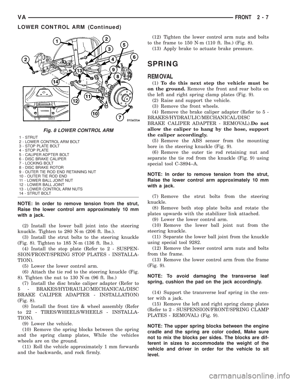
(5) Remove the retaining nut holding the tie rod to
the steering knuckle (Fig. 8).
(6) Seperate the tie rod off the steering knuckle
(Fig. 8) using special tool C-3894±A.
NOTE: In order to remove tension from the strut,
Raise the lower control arm approximately 10 mm
with a jack.
(7) Remove the strut bolts from the steering
knuckle (Fig. 8).
(8) Remove the stop plate bolts and rotate the
plate upwards with the stabilizer link attached (Fig.
8).
(9) Lower the lower control arm.
(10) Remove the lower ball joint nut from the
steering knuckle (Fig. 8).
(11) Separate the lower ball joint from the knuckle
using special tool 9282.
(12) Remove the lower control arm nuts and bolts
from the frame (Fig. 8).
(13) Remove the lower control arm.
INSTALLATION
(1) Install the lower control arm to the frame.
Hand tighten the nuts and bolts.
Fig. 7 LOWER BALL JOINT
1 - LOWER CONTROL ARM
2 - LOWER BALL JOINT
2 - 6 FRONTVA
KNUCKLE (Continued)
Page 27 of 1232
NOTE: In order to remove tension from the strut,
Raise the lower control arm approximately 10 mm
with a jack.
(2) Install the lower ball joint into the steering
knuckle. Tighten to 280 N´m (206 ft. lbs.).
(3) Install the strut bolts to the steering knuckle
(Fig. 8). Tighten to 185 N´m (136 ft. lbs.).
(4) Install the stop plate (Refer to 2 - SUSPEN-
SION/FRONT/SPRING STOP PLATES - INSTALLA-
TION).
(5) Lower the lower control arm.
(6) Attach the tie rod to the steering knuckle (Fig.
8). Tighten the nut to 130 N´m (96 ft. lbs.)
(7) Install the disc brake caliper adapter (Refer to
5 - BRAKES/HYDRAULIC/MECHANICAL/DISC
BRAKE CALIPER ADAPTER - INSTALLATION)
(Fig. 8).
(8) Install the front tire & wheel assembly (Refer
to 22 - TIRES/WHEELS/WHEELS - INSTALLA-
TION).
(9) Lower the vehicle.
(10) Remove the spring blocks between the spring
and the spring clamp plates, While the vehicles
wheels are on the ground.
(11) Roll the vehicle approximately 1 mm forwards
and the backwards, and rock firmly.(12) Tighten the lower control arm nuts and bolts
to the frame to 150 N´m (110 ft. lbs.) (Fig. 8).
(13) Apply brake to actuate brake pressure.
SPRING
REMOVAL
(1)To do this next step the vehicle must be
on the ground.Remove the front and rear bolts on
the left and right spring clamp plates (Fig. 9).
(2) Raise and support the vehicle.
(3) Remove the front wheels.
(4) Remove the brake caliper adapter (Refer to 5 -
BRAKES/HYDRAULIC/MECHANICAL/DISC
BRAKE CALIPER ADAPTER - REMOVAL).Do not
allow the caliper to hang by the hose, support
the caliper accordingly.
(5) Remove the ABS sensor from the mounting
bore in the steering knuckle (Fig. 9).
(6) Remove the outer tie rod retaining nut and
separate the tie rod from the knuckle (Fig. 9) using
special tool C-3894±A.
NOTE: In order to remove tension from the strut,
Raise the lower control arm approximately 10 mm
with a jack.
(7) Remove the strut bolts from the steering
knuckle.
(8) Remove both stop plate bolts and rotate the
plates upwards with the stabilizer link attached.
(9) Lower the lower control arm.
(10) Remove the lower ball joint nut from the
steering knuckle.
(11) Separate the lower ball joint from the knuckle
using special tool 9282.
(12) Remove the lower control arm nuts and bolts
from the frame.
(13) Remove the lower control arm from the frame
(Fig. 9).
NOTE: To avoid damaging the transverse leaf
spring, cushion the pad on the jack accordingly.
(14) Support the transverse leaf spring in the cen-
ter with a jack.
(15) Remove the left and right spring clamp plates
(Refer to 2 - SUSPENSION/FRONT/SPRING CLAMP
PLATES - REMOVAL) (Fig. 9).
NOTE: The upper spring blocks between the engine
cradle and the spring are color coded, Make sure
not to mix the blocks per sides. The blocks are dif-
ferent in sizes to accommodate the weight of the
vehicle and driver in order for the vehicle to sit
level.
Fig. 8 LOWER CONTROL ARM
1 - STRUT
2 - LOWER CONTROL ARM BOLT
3 - STOP PLATE BOLT
4 - STOP PLATE
5 - CALIPER ADPTER BOLT
6 - DISC BRAKE CALIPER
7 - LOCKING BOLT
8 - DISC BRAKE ROTOR
9 - OUTER TIE ROD END RETAINING NUT
10 - OUTER TIE ROD END
11 - LOWER BALL JOINT NUT
12 - LOWER BALL JOINT
13 - LOWER CONTROL ARM NUTS
14 - STRUT BOLT
VAFRONT 2 - 7
LOWER CONTROL ARM (Continued)
Page 28 of 1232
(16) Lower the jack and remove the transverse leaf
spring towards the side.
INSTALLATION
NOTE: To avoid damaging the transverse leaf
spring, cushion the pad on the jack accordingly.
NOTE: Hand tighten all bolts until vehicle is on the
ground, unless the bushings may become distorted.
NOTE: The height blocks between the engine cradle
and the spring are color coded, Make sure not to
mix the blocks per sides. The blocks are different in
sizes to accommodate the weight of the vehicle and
driver in order for the vehicle to sit level.
(1) Install the transverse leaf spring in the center
with a jack with all the rubber mounts attached.
(2) Install the lower control arm to the frame (Fig.
9).
(3) Install the knuckle on the lower ball joint.(4) Raise the lower control arm approximately 10
mm with a jack.
(5) Install both stop plate bolts to the lower control
arm
(6) Install the strut bolts to the steering knuckle.
(7) Reinstall the tie rod to the steering knuckle
(Fig. 9). Tighten to 150 N´m (110 ft. lbs.).
(8) Install the ABS sensor all the way into the
steering knuckle, the sensor will adjust automatically
when the vehicle is moved (Fig. 9).
(9) Install the disc brake caliper adapter (Fig. 9).
Tighten to 170 N´m (125 ft. lbs.).
(10) Install the front wheels.
(11) Lower the vehicle.
(12) Install the spring clamp plates (Fig. 9).
Tighten (M-10 bolts) to 65 N´m (48 ft. lbs.) (M-12
bolts) to 130 N´m (96 ft. lbs.).
(13) Roll the vehicle approximately 1 mm forwards
and the backwards, and rock firmly.
(14) Tighten the nuts on the lower control arm to
the frame to 150 N´m (110 ft. lbs.).
(15) Apply brake to actuate brake pressure.
SPRING CLAMP PLATES
REMOVAL
(1) Raise and support the vehicle.
(2) Install a jack under the lower ball joint and
lower the weight of the vehicle enough to allow a
wrench between the lower control arm and the
bracket tighten the nut.
(3) Remove the front and rear bolts to the spring
clamp plates.
(4) Remove the four inner retaining bolts and
nuts.
(5) Remove the spring clamp plate and rubber
block.
(6) Remove the shear bushings from the front and
rear bolts.
INSTALLATION
(1) Install a jack under the lower ball joint and
lower the weight of the vehicle enough to allow a
wrench between the lower control arm and the
bracket tighten the nut.
(2) Fit one spring clamp plate together with the
lower spring rubber block.
(3) Install the bolt with the shear bushing on the
rear mounting,Do not tighten yet.
(4) Install the four retaining bolts for the spring
clamp plate. Tighten to 65 N´m (48 ft.lbs.).
(5) Align the holes for the front clamp plate joint
using a suitable drift (shear bushing not installed).
(6) Remove the alignment drift.
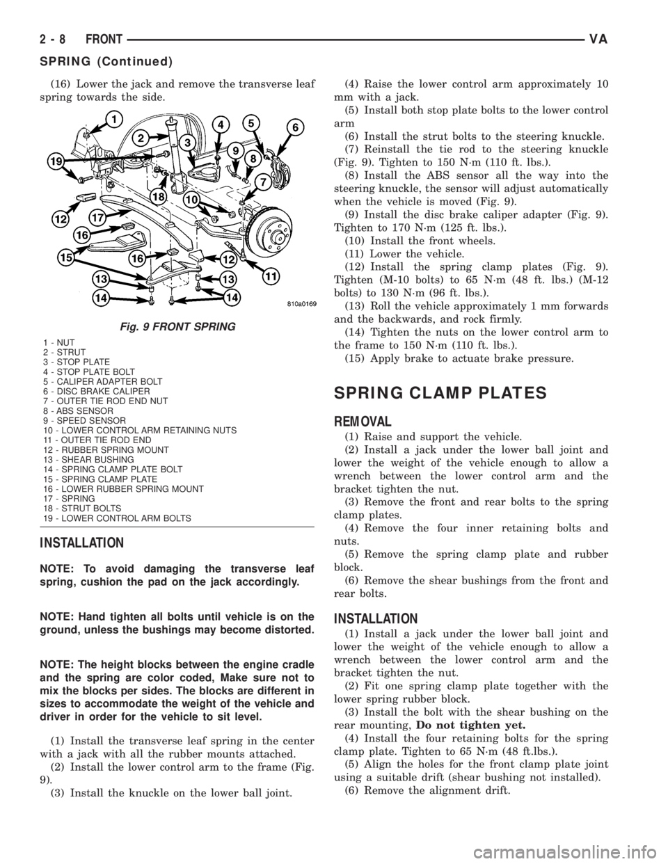
Fig. 9 FRONT SPRING
1 - NUT
2 - STRUT
3 - STOP PLATE
4 - STOP PLATE BOLT
5 - CALIPER ADAPTER BOLT
6 - DISC BRAKE CALIPER
7 - OUTER TIE ROD END NUT
8 - ABS SENSOR
9 - SPEED SENSOR
10 - LOWER CONTROL ARM RETAINING NUTS
11 - OUTER TIE ROD END
12 - RUBBER SPRING MOUNT
13 - SHEAR BUSHING
14 - SPRING CLAMP PLATE BOLT
15 - SPRING CLAMP PLATE
16 - LOWER RUBBER SPRING MOUNT
17 - SPRING
18 - STRUT BOLTS
19 - LOWER CONTROL ARM BOLTS
2 - 8 FRONTVA
SPRING (Continued)
Page 29 of 1232
(7) Insert the shear bushing and retaining bolt
into the hole and tighten to 130 N´m (96 ft.lbs.).
(8) Remove the jack and lower the vehicle.
SPRING STOP PLATES
REMOVAL
(1) Raise and support the vehicle.
(2) Remove the tire and wheel assembly.
(3) Remove the lower end of the stabilizer link
from the stop plate.
(4) Remove the three bolts retaining the spring
stop plate from the lower control arm.
INSTALLATION
(1) Install the spring stop plate to the lower con-
trol arm. Tighten the bolts to 60 N´m (44 ft. lbs.).
(2) Install the stabilizer link to the spring stop
plate.
(3) Install the tire and wheel assembly.
(4) Lower the vehicle.
STABILIZER BAR
DESCRIPTION
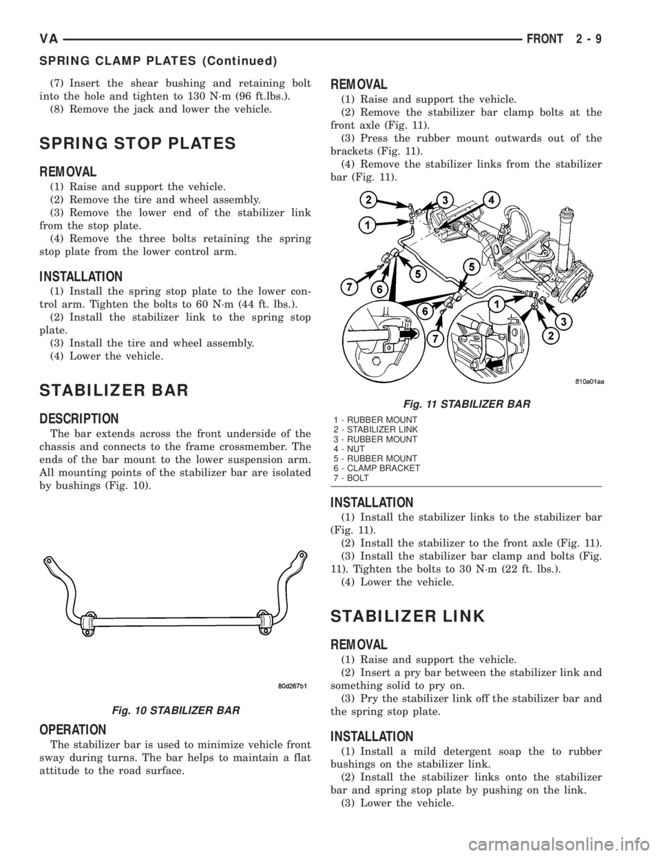
The bar extends across the front underside of the
chassis and connects to the frame crossmember. The
ends of the bar mount to the lower suspension arm.
All mounting points of the stabilizer bar are isolated
by bushings (Fig. 10).
OPERATION
The stabilizer bar is used to minimize vehicle front
sway during turns. The bar helps to maintain a flat
attitude to the road surface.
REMOVAL
(1) Raise and support the vehicle.
(2) Remove the stabilizer bar clamp bolts at the
front axle (Fig. 11).
(3) Press the rubber mount outwards out of the
brackets (Fig. 11).
(4) Remove the stabilizer links from the stabilizer
bar (Fig. 11).
INSTALLATION
(1) Install the stabilizer links to the stabilizer bar
(Fig. 11).
(2) Install the stabilizer to the front axle (Fig. 11).
(3) Install the stabilizer bar clamp and bolts (Fig.
11). Tighten the bolts to 30 N´m (22 ft. lbs.).
(4) Lower the vehicle.
STABILIZER LINK
REMOVAL
(1) Raise and support the vehicle.
(2) Insert a pry bar between the stabilizer link and
something solid to pry on.
(3) Pry the stabilizer link off the stabilizer bar and
the spring stop plate.
INSTALLATION
(1) Install a mild detergent soap the to rubber
bushings on the stabilizer link.
(2) Install the stabilizer links onto the stabilizer
bar and spring stop plate by pushing on the link.
(3) Lower the vehicle.
Fig. 10 STABILIZER BAR
Fig. 11 STABILIZER BAR
1 - RUBBER MOUNT
2 - STABILIZER LINK
3 - RUBBER MOUNT
4 - NUT
5 - RUBBER MOUNT
6 - CLAMP BRACKET
7 - BOLT
VAFRONT 2 - 9
SPRING CLAMP PLATES (Continued)
Page 34 of 1232
SPRING
DESCRIPTION
The rear suspension system uses a multi-leaf
springs and a solid drive axle. The forward end of the
springs are mounted to the body rail hangers
through rubber bushings. The rearward end of the
springs are attached to the body by the use of shack-
les. The spring and shackles use rubber bushings.
OPERATION
The springs control ride quality and maintain vehi-
cle ride height. The shackles allow the springs to
change their length as the vehicle moves over various
road conditions.
REMOVAL
REMOVAL - (SRW)
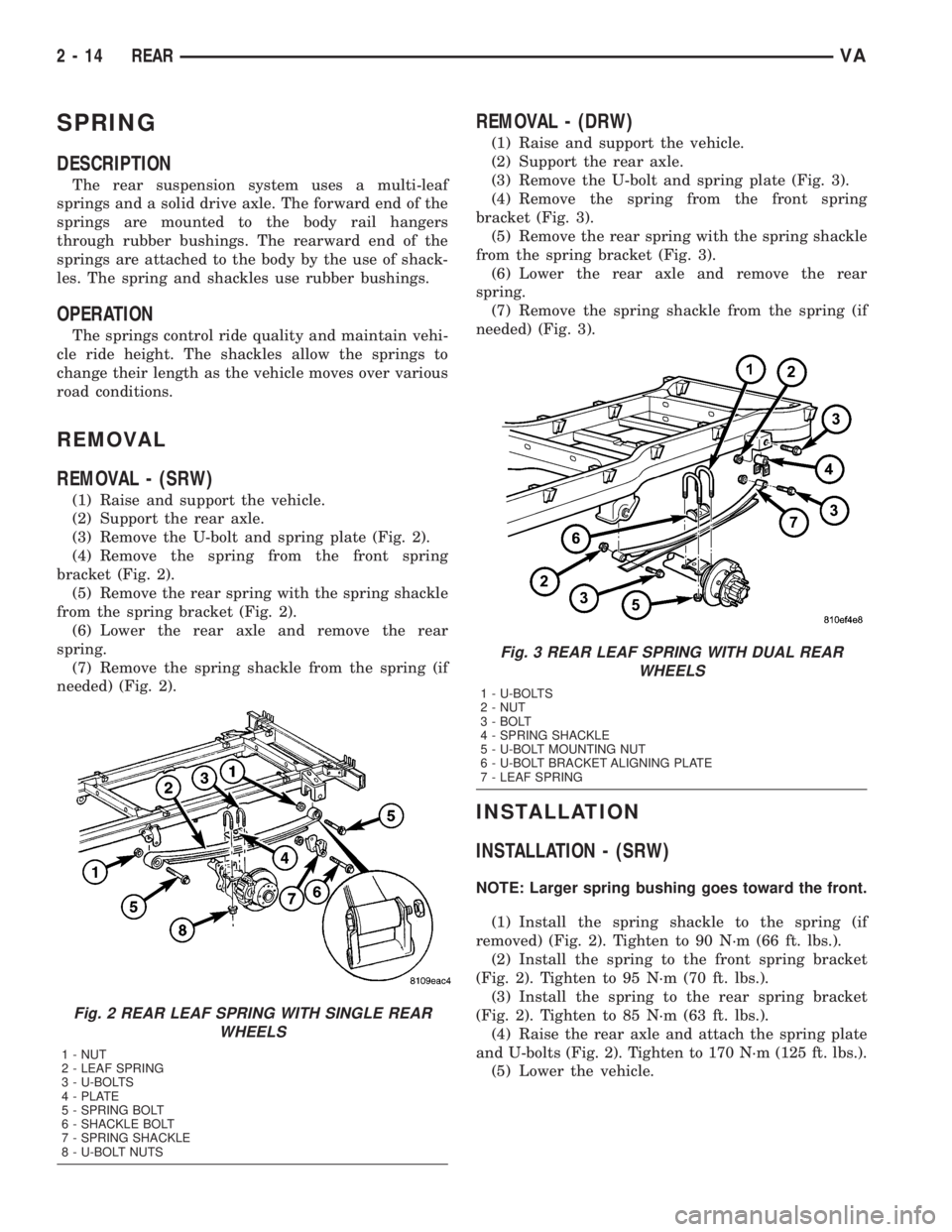
(1) Raise and support the vehicle.
(2) Support the rear axle.
(3) Remove the U-bolt and spring plate (Fig. 2).
(4) Remove the spring from the front spring
bracket (Fig. 2).
(5) Remove the rear spring with the spring shackle
from the spring bracket (Fig. 2).
(6) Lower the rear axle and remove the rear
spring.
(7) Remove the spring shackle from the spring (if
needed) (Fig. 2).
REMOVAL - (DRW)
(1) Raise and support the vehicle.
(2) Support the rear axle.
(3) Remove the U-bolt and spring plate (Fig. 3).
(4) Remove the spring from the front spring
bracket (Fig. 3).
(5) Remove the rear spring with the spring shackle
from the spring bracket (Fig. 3).
(6) Lower the rear axle and remove the rear
spring.
(7) Remove the spring shackle from the spring (if
needed) (Fig. 3).
INSTALLATION
INSTALLATION - (SRW)
NOTE: Larger spring bushing goes toward the front.
(1) Install the spring shackle to the spring (if
removed) (Fig. 2). Tighten to 90 N´m (66 ft. lbs.).
(2) Install the spring to the front spring bracket
(Fig. 2). Tighten to 95 N´m (70 ft. lbs.).
(3) Install the spring to the rear spring bracket
(Fig. 2). Tighten to 85 N´m (63 ft. lbs.).
(4) Raise the rear axle and attach the spring plate
and U-bolts (Fig. 2). Tighten to 170 N´m (125 ft. lbs.).
(5) Lower the vehicle.
Fig. 2 REAR LEAF SPRING WITH SINGLE REAR
WHEELS
1 - NUT
2 - LEAF SPRING
3 - U-BOLTS
4 - PLATE
5 - SPRING BOLT
6 - SHACKLE BOLT
7 - SPRING SHACKLE
8 - U-BOLT NUTS
Fig. 3 REAR LEAF SPRING WITH DUAL REAR
WHEELS
1 - U-BOLTS
2 - NUT
3 - BOLT
4 - SPRING SHACKLE
5 - U-BOLT MOUNTING NUT
6 - U-BOLT BRACKET ALIGNING PLATE
7 - LEAF SPRING
2 - 14 REARVA
Page 35 of 1232
INSTALLATION - (DRW)
NOTE: Larger spring bushing goes toward the front.
(1) Install the spring shackle to the spring (if
removed) (Fig. 3). Tighten to 185 N´m (136 ft. lbs.).
(2) Install the spring to the front spring bracket
(Fig. 3). Tighten to 185 N´m (136 ft. lbs.).
(3) Install the spring to the rear spring bracket
(Fig. 3). Tighten to 185 N´m (136 ft. lbs.).
(4) Raise the rear axle and attach the spring plate
and U-bolts (Fig. 3). Tighten to 170 N´m (125 ft. lbs.).
(5) Lower the vehicle.
SPRING SHACKLE
REMOVAL
(1) Raise and support the vehicle.
(2) Support the rear axle.
(3) Remove both the rear spring shackles from the
spring bracket.
(4) Lower the rear axle and remove the rear spring
shackle from the spring.
INSTALLATION
(1) Install the spring shackle to the spring.
Tighten to 90 N´m (66 ft. lbs.).
(2) Raise the rear axle while installing the spring
shackle to the spring bracket. Tighten to 85 N´m (63
ft. lbs.).
(3) Lower the vehicle.
STABILIZER BAR
REMOVAL
(1) Raise and support the vehicle.
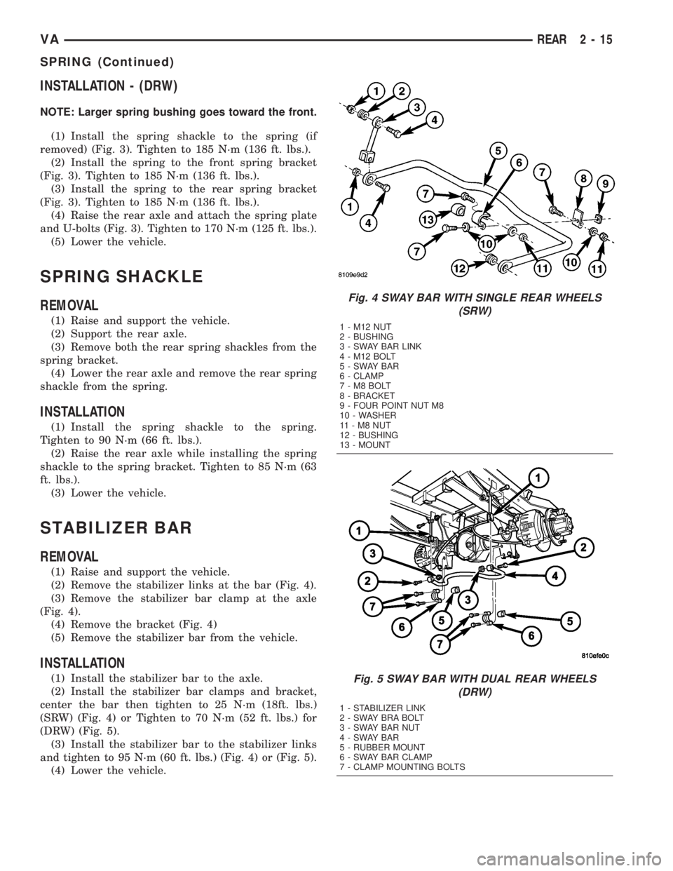
(2) Remove the stabilizer links at the bar (Fig. 4).
(3) Remove the stabilizer bar clamp at the axle
(Fig. 4).
(4) Remove the bracket (Fig. 4)
(5) Remove the stabilizer bar from the vehicle.
INSTALLATION
(1) Install the stabilizer bar to the axle.
(2) Install the stabilizer bar clamps and bracket,
center the bar then tighten to 25 N´m (18ft. lbs.)
(SRW) (Fig. 4) or Tighten to 70 N´m (52 ft. lbs.) for
(DRW) (Fig. 5).
(3) Install the stabilizer bar to the stabilizer links
and tighten to 95 N´m (60 ft. lbs.) (Fig. 4) or (Fig. 5).
(4) Lower the vehicle.
Fig. 4 SWAY BAR WITH SINGLE REAR WHEELS
(SRW)
1 - M12 NUT
2 - BUSHING
3 - SWAY BAR LINK
4 - M12 BOLT
5-SWAYBAR
6 - CLAMP
7-M8BOLT
8 - BRACKET
9 - FOUR POINT NUT M8
10 - WASHER
11-M8NUT
12 - BUSHING
13 - MOUNT
Fig. 5 SWAY BAR WITH DUAL REAR WHEELS
(DRW)
1 - STABILIZER LINK
2 - SWAY BRA BOLT
3 - SWAY BAR NUT
4-SWAYBAR
5 - RUBBER MOUNT
6 - SWAY BAR CLAMP
7 - CLAMP MOUNTING BOLTS
VAREAR 2 - 15
SPRING (Continued)
Page 42 of 1232
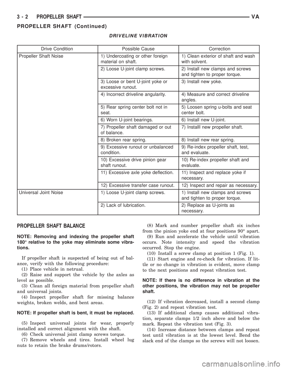
DRIVELINE VIBRATION
Drive Condition Possible Cause Correction
Propeller Shaft Noise 1) Undercoating or other foreign
material on shaft.1) Clean exterior of shaft and wash
with solvent.
2) Loose U-joint clamp screws. 2) Install new clamps and screws
and tighten to proper torque.
3) Loose or bent U-joint yoke or
excessive runout.3) Install new yoke.
4) Incorrect driveline angularity. 4) Measure and correct driveline
angles.
5) Rear spring center bolt not in
seat.5) Loosen spring u-bolts and seat
center bolt.
6) Worn U-joint bearings. 6) Install new U-joint.
7) Propeller shaft damaged or out
of balance.7) Installl new propeller shaft.
8) Broken rear spring. 8) Install new rear spring.
9) Excessive runout or unbalanced
condition.9) Re-index propeller shaft, test,
and evaluate.
10) Excessive drive pinion gear
shaft runout.10) Re-index propeller shaft and
evaluate.
11) Excessive axle yoke deflection. 11) Inspect and replace yoke if
necessary.
12) Excessive transfer case runout. 12) Inspect and repair as necessary.
Universal Joint Noise 1) Loose U-joint clamp screws. 1) Install new clamps and screws
and tighten to proper torque.
2) Lack of lubrication. 2) Replace as U-joints as
necessary.
PROPELLER SHAFT BALANCE
NOTE: Removing and indexing the propeller shaft
180É relative to the yoke may eliminate some vibra-
tions.
If propeller shaft is suspected of being out of bal-
ance, verify with the following procedure:
(1) Place vehicle in netrual.
(2) Raise and support the vehicle by the axles as
level as possible.
(3) Clean all foreign material from propeller shaft
and universal joints.
(4) Inspect propeller shaft for missing balance
weights, broken welds, and bent areas.
NOTE: If propeller shaft is bent, it must be replaced.
(5) Inspect universal joints for wear, properly
installed and correct alignment with the shaft.
(6) Check universal joint clamp screws torque.
(7) Remove wheels and tires. Install wheel lug
nuts to retain the brake drums/rotors.(8) Mark and number propeller shaft six inches
from the pinion yoke end at four positions 90É apart.
(9) Run and accelerate the vehicle until vibration
occurs. Note intensity and speed the vibration
occurred. Stop the engine.
(10) Install a screw clamp at position 1 (Fig. 1).
(11) Start engine and re-check for vibration. If lit-
tle or no change in vibration is evident, move clamp
to the next positions and repeat vibration test.
NOTE: If there is no difference in vibration at the
other positions, the vibration may not be propeller
shaft.
(12) If vibration decreased, install a second clamp
(Fig. 2) and repeat vibration test.
(13) If additional clamp causes additional vibra-
tion, separate clamps 1/2 inch above and below the
mark. Repeat the vibration test (Fig. 3).
(14) Increase distance between clamps and repeat
test until vibration is at the lowest level. Bend the
slack end of the clamps so the screws will not loosen.
3 - 2 PROPELLER SHAFTVA
PROPELLER SHAFT (Continued)
Page 46 of 1232
PROPELLER SHAFT
REMOVAL
(1) Secure vehicle to prevent it from rolling.
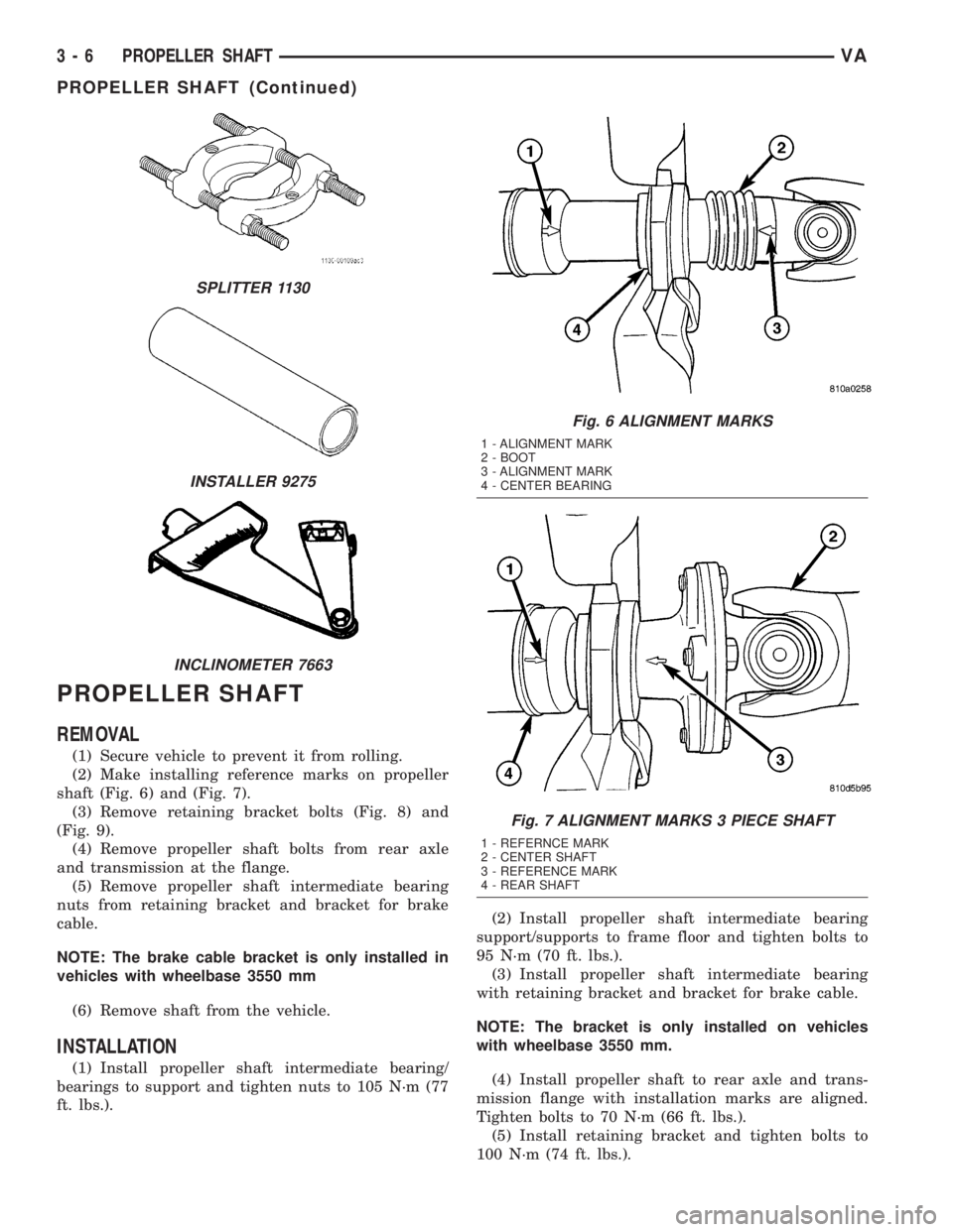
(2) Make installing reference marks on propeller
shaft (Fig. 6) and (Fig. 7).
(3) Remove retaining bracket bolts (Fig. 8) and
(Fig. 9).
(4) Remove propeller shaft bolts from rear axle
and transmission at the flange.
(5) Remove propeller shaft intermediate bearing
nuts from retaining bracket and bracket for brake
cable.
NOTE: The brake cable bracket is only installed in
vehicles with wheelbase 3550 mm
(6) Remove shaft from the vehicle.
INSTALLATION
(1) Install propeller shaft intermediate bearing/
bearings to support and tighten nuts to 105 N´m (77
ft. lbs.).(2) Install propeller shaft intermediate bearing
support/supports to frame floor and tighten bolts to
95 N´m (70 ft. lbs.).
(3) Install propeller shaft intermediate bearing
with retaining bracket and bracket for brake cable.
NOTE: The bracket is only installed on vehicles
with wheelbase 3550 mm.
(4) Install propeller shaft to rear axle and trans-
mission flange with installation marks are aligned.
Tighten bolts to 70 N´m (66 ft. lbs.).
(5) Install retaining bracket and tighten bolts to
100 N´m (74 ft. lbs.).
SPLITTER 1130
INSTALLER 9275
INCLINOMETER 7663
Fig. 6 ALIGNMENT MARKS
1 - ALIGNMENT MARK
2 - BOOT
3 - ALIGNMENT MARK
4 - CENTER BEARING
Fig. 7 ALIGNMENT MARKS 3 PIECE SHAFT
1 - REFERNCE MARK
2 - CENTER SHAFT
3 - REFERENCE MARK
4 - REAR SHAFT
3 - 6 PROPELLER SHAFTVA
PROPELLER SHAFT (Continued)