2005 MERCEDES-BENZ SPRINTER refrigerant type
[x] Cancel search: refrigerant typePage 1137 of 1232
The compressor clutch engagement is controlled by
several components:
²A/C switch on the A/C-heater control panel
²Evaporator temperature sensor
²A/C pressure transducer
²Air temperature sensor
²CAN bus messages
The compressor clutch is de-energized under any of
the following conditions:
²Blocked compressor (thermal fuse in the pulley)
²Low pressure in the system
²Low evaporator temperature
²Hard acceleration (WOT)
²High coolant temperatures
STANDARD PROCEDURE
STANDARD PROCEDURE - COMPRESSOR
CLUTCH AIR GAP
If a new clutch plate and/or clutch pulley are being
used, the air gap between the clutch plate and clutch
pulley must be checked using the following proce-
dure:
(1) Using feeler gauges, measure the air gap
between the clutch plate and the clutch pulley fric-
tion surfaces.
(2) If the air gap is not between 0.5 and 0.9 mm
(0.020 and 0.035 in.), add or subtract shims until the
desired air gap is obtained.
NOTE: The shims may compress after tightening
the compressor shaft bolt. Check the air gap in four
or more places on the clutch plate to verify that theair gap is still correct. Spin the clutch pulley before
making the final air gap check.
STANDARD PROCEDURE - COMPRESSOR
CLUTCH BREAK-IN
After a new compressor clutch has been installed,
cycle the compressor clutch approximately twenty
times (five seconds on, then five seconds off). During
this procedure, set the heater-A/C control in the
Recirculation Mode, the A/C button in the on posi-
tion, the blower motor switch in the highest speed
position, and the engine speed at 1500 to 2000 rpm.
This procedure (burnishing) will seat the opposing
friction surfaces and provide a higher compressor
clutch torque capability.
REMOVAL
The refrigerant system can remain fully-charged
during compressor clutch, pulley, or coil replacement.
The compressor clutch can be serviced in the vehicle.
(1) Disconnect and isolate the battery negative
cable.
(2) Remove the serpentine drive belt (Refer to 7 -
COOLING/ACCESSORY DRIVE/DRIVE BELTS -
REMOVAL).
(3) Disconnect the engine wire harness connector
for the compressor clutch coil from the clutch coil
wire harness connector on the top of the compressor.
(4) Disengage the retainer on the engine wire har-
ness compressor clutch coil lead from the bracket on
the top of the compressor.
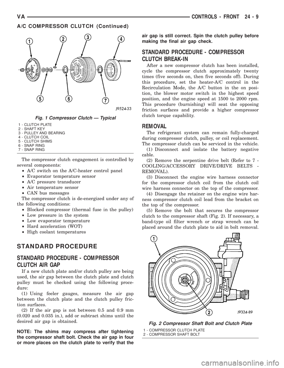
(5) Remove the bolt that secures the compressor
clutch to the compressor shaft (Fig. 2). If necessary, a
band-type oil filter wrench or strap wrench can be
placed around the clutch plate to aid in bolt removal.
Fig. 1 Compressor Clutch Ð Typical
1 - CLUTCH PLATE
2 - SHAFT KEY
3 - PULLEY AND BEARING
4 - CLUTCH COIL
5 - CLUTCH SHIMS
6 - SNAP RING
7 - SNAP RING
Fig. 2 Compressor Shaft Bolt and Clutch Plate
1 - COMPRESSOR CLUTCH PLATE
2 - COMPRESSOR SHAFT BOLT
VACONTROLS - FRONT 24 - 9
A/C COMPRESSOR CLUTCH (Continued)
Page 1173 of 1232
CAUTION
CAUTION
CAUTION: Liquid refrigerant is corrosive to metal
surfaces. Follow the operating instructions supplied
with the service equipment being used.
Never add R-12 to a refrigerant system designed to
use R-134a. Damage to the system will result.
R-12 refrigerant oil must not be mixed with R-134a
refrigerant oil. They are not compatible.
Do not use R-12 equipment or parts on the R-134a
system. Damage to the system will result.
Do not overcharge the refrigerant system. This will
cause excessive compressor head pressure and
can cause noise and system failure.
Recover the refrigerant before opening any fitting
or connection. Open the fittings with caution, even
after the system has been discharged. Never open
or loosen a connection before recovering the refrig-
erant.
The refrigerant system must always be evacuated
before charging.
Do not open the refrigerant system or uncap a
replacement component until you are ready to ser-
vice the system. This will prevent contamination in
the system.
Before disconnecting a component, clean the out-
side of the fittings thoroughly to prevent contami-
nation from entering the refrigerant system.
Immediately after disconnecting a component from
the refrigerant system, seal the open fittings with a
cap or plug.
Before connecting an open refrigerant fitting,
always install a new seal or gasket. Coat the fitting
and seal with clean refrigerant oil before connect-
ing.
Do not remove the sealing caps from a replacement
component until it is to be installed.
When installing a refrigerant line, avoid sharp
bends that may restrict refrigerant flow. Position the
refrigerant lines away from exhaust system compo-
nents or any sharp edges, which may damage the
line.
Tighten refrigerant fittings only to the specified
torque. The aluminum fittings used in the refriger-
ant system will not tolerate overtightening.
When disconnecting a refrigerant fitting, use a
wrench on both halves of the fitting. This will pre-
vent twisting of the refrigerant lines or tubes.
Refrigerant oil will absorb moisture from the atmo-
sphere if left uncapped. Do not open a container of
refrigerant oil until you are ready to use it. Replace
the cap on the oil container immediately after using.
Store refrigerant oil only in a clean, airtight, and
moisture-free container.Keep service tools and the work area clean. Con-
tamination of the refrigerant system through care-
less work habits must be avoided.REFRIGERANT HOSES/LINES/TUBES
PRECAUTIONS
Kinks or sharp bends in the refrigerant plumbing
will reduce the capacity of the entire system. High
pressures are produced in the system when it is oper-
ating. Extreme care must be exercised to make sure
that all refrigerant system connections are pressure
tight.
A good rule for the flexible hose refrigerant lines is
to keep the radius of all bends at least ten times the
diameter of the hose. Sharp bends will reduce the
flow of refrigerant. The flexible hose lines should be
routed so they are at least 80 millimeters (3 inches)
from the exhaust manifold. It is a good practice to
inspect all flexible refrigerant system hose lines at
least once a year to make sure they are in good con-
dition and properly routed.
There are two types of refrigerant fittings:
²All fittings with O-rings need to be coated with
refrigerant oil before installation. Use only O-rings
that are the correct size and approved for use with
R-134a refrigerant. Failure to do so may result in a
leak.
²Unified plumbing connections with gaskets can-
not be serviced with O-rings. The gaskets are not
reusable and new gaskets do not require lubrication
before installing.
Using the proper tools when making a refrigerant
plumbing connection is very important. Improper
tools or improper use of the tools can damage the
refrigerant fittings. Always use two wrenches when
loosening or tightening tube fittings. Use one wrench
to hold one side of the connection stationary, while
loosening or tightening the other side of the connec-
tion with a second wrench.
The refrigerant must be recovered completely from
the system before opening any fitting or connection.
Open the fittings with caution, even after the refrig-
erant has been recovered. If any pressure is noticed
as a fitting is loosened, tighten the fitting and
recover the refrigerant from the system again.
Do not discharge refrigerant into the atmosphere.
Use an R-134a refrigerant recovery/recycling device
that meets SAE Standard J2210.
The refrigerant system will remain chemically sta-
ble as long as pure, moisture-free R-134a refrigerant
and refrigerant oil is used. Dirt, moisture, or air can
upset this chemical stability. Operational troubles or
serious damage can occur if foreign material is
present in the refrigerant system.
VAPLUMBING 24 - 45
PLUMBING (Continued)
Page 1177 of 1232
²If a single probe is used, record the temperature
of the evaporator inlet tube. Then remove the probe
from the inlet tube and attach it to the evaporator
outlet tube just before the collar of the refrigerant
line connector fitting. The probe must make contact
with the bottom surface of the evaporator outlet tube.
Allow the thermocouple and meter time to stabilize,
then record the temperature of the evaporator outlet
tube. Subtract the inlet tube temperature reading
from the outlet tube temperature reading.
²If dual probes are used, record the temperatures
of both the evaporator inlet and outlet tubes. Then
subtract the inlet tube temperature reading from the
outlet tube temperature reading.(9) If the measured temperature differential is
higher than 22É C to 26É C (40É F to 47É F), add 0.4
kilograms (14 ounces) of refrigerant.
(10) Allow three to five minutes for the refrigerant
system to stabilize, then take a second set of thermo-
couple measurements. Record the temperature differ-
ence to determine if an additional charge is required.
(11) Record the compressor discharge pressure. If
the reading is higher than the pressure shown in the
Compressor Discharge Pressure Chart, the system
could be overcharged. If the reading is equal to, or
lower, than the pressure shown in the chart, continue
with this procedure.
Compressor Discharge Pressure Chart
Ambient
Temperature16ÉC
(60ÉF)21ÉC
(70ÉF)27ÉC
(80ÉF)32ÉC
(90ÉF)38ÉC
(100ÉF)43ÉC
(110ÉF)
Compressor
Discharge
Pressure1378 kPa
(200 psi)1516 kPa
(220 psi)1723 kPa
(250psi)1930 kPa
(280 psi)2206 kPa
(320 psi)2413 kPa
(350 psi)
(12)EXAMPLE:The ambient temperature is 21É
C (70É F). The evaporator inlet tube temperature is
12É C (54É F) and the evaporator outlet tube temper-
ature is 10É C (50É F). Subtract the inlet tube tem-
perature from the outlet tube temperature. The
difference is -2É C (-4É F). With a -2É C (-4É F) tem-
perature differential at 21É C (70É F) ambient tem-
perature, the system is fully charged.
(13) Add enough refrigerant to bring the refriger-
ant system up to a full charge.
(14) Remove the jumper wire from the low pres-
sure cycling clutch switch wire harness connector
and plug the connector back into the switch.
SPECIFICATIONS
CHARGE CAPACITY
Always refer to the underhood HVAC Specification
Tag for the latest fill specification for the model being
serviced.
A/C COMPRESSOR
DESCRIPTION
The air conditioning system uses a Nippondenso
7SBU16C double-acting, variable swash plate-type
compressor on all models. This compressor has a
label identifying the use of R-134a refrigerant and
both the suction and discharge ports located on the
cylinder head.
OPERATION
The compressor is driven by the engine through an
electric clutch, drive pulley and belt arrangement.
The compressor is lubricated by refrigerant oil that is
circulated throughout the refrigerant system with the
refrigerant.
The compressor draws in low-pressure refrigerant
vapor from the evaporator through its suction port. It
then compresses the refrigerant into a high-pressure,
high-temperature refrigerant vapor, which is then
pumped to the condenser through the compressor dis-
charge port.
The compressor cannot be repaired. If faulty or
damaged, the entire compressor assembly must be
replaced. The compressor clutch, pulley, and coil, are
available for service.
DIAGNOSIS AND TESTING - COMPRESSOR
NOISE
When investigating an air conditioning related
noise, you must first know the conditions under
which the noise occurs. These conditions include:
weather, vehicle speed, transmission in gear or neu-
tral, engine speed, engine temperature, and any
other special conditions. Noises that develop during
air conditioning operation can often be misleading.
For example: What sounds like a failed front bearing
or connecting rod, may be caused by loose bolts, nuts,
mounting brackets, or a loose compressor clutch
assembly.
VAPLUMBING 24 - 49
PLUMBING (Continued)
Page 1180 of 1232
(6) Connect the discharge line fitting to the com-
pressor discharge port.
(7) Install the bolt that secures the discharge line
fitting to the top of the compressor. Tighten the bolt
to 23 N´m (17 ft. lbs.).
(8) Remove plugs or tape from the suction line fit-
ting and the compressor suction port.
(9) Lubricate a new rubber o-ring seal with clean
refrigerant oil and install the seal onto the suction
line fitting.
(10) Connect the suction line fitting to the com-
pressor suction port.
(11) Install the bolt that secures the suction line
fitting to the top of the compressor. Tighten the bolt
to 23 N´m (17 ft. lbs.).
(12) Install the accessory drive belt (Refer to 7 -
COOLING/ACCESSORY DRIVE/DRIVE BELTS -
INSTALLATION).
(13) Reconnect the negative battery cable.
(14) Evacuate the refrigerant system (Refer to 24 -
HEATING & AIR CONDITIONING/PLUMBING -
STANDARD PROCEDURE - REFRIGERANT SYS-
TEM EVACUATE).
(15) Charge the refrigerant system (Refer to 24 -
HEATING & AIR CONDITIONING/PLUMBING -
STANDARD PROCEDURE - REFRIGERANT SYS-
TEM CHARGE).
A/C CONDENSER
DESCRIPTION
The condenser is located in the air flow in front of
the engine cooling radiator. The condenser is a heat
exchanger that allows the high-pressure refrigerant
gas being discharged by the compressor to give up its
heat to the air passing over the condenser fins.
OPERATION
When the refrigerant gas gives up its heat, it con-
denses. When the refrigerant leaves the condenser, it
has become a high-pressure liquid refrigerant. The
volume of air flowing over the condenser fins is crit-
ical to the proper cooling performance of the air con-
ditioning system. Therefore, it is important that
there are no objects placed in front of the radiator
grille openings in the front of the vehicle or foreign
material on the condenser fins that might obstruct
proper air flow. Also, any factory-installed air seals or
shrouds must be properly reinstalled following radia-
tor or condenser service.
The condenser cannot be repaired and, if faulty or
damaged, it must be replaced.
REMOVAL
WARNING: REVIEW THE WARNINGS AND CAU-
TIONS IN THE FRONT OF THIS SECTION BEFORE
PERFORMING THE FOLLOWING OPERATION (Refer
to 24 - HEATING & AIR CONDITIONING/PLUMBING -
WARNING) and (Refer to 24 - HEATING & AIR CON-
DITIONING/PLUMBING - CAUTION).
(1) Disconnect and isolate the battery negative
cable.
(2) Recover the refrigerant from the refrigerant
system (Refer to 24 - HEATING & AIR CONDITION-
ING/PLUMBING - STANDARD PROCEDURE -
REFRIGERANT RECOVERY).
(3) Remove the front fascia.
(4) Remove the grille (Refer to 23 - BODY/EXTE-
RIOR/GRILLE - REMOVAL).
(5) Remove the headlamps from their mounts.
(6) Remove the radiator crossmember (Refer to 23
- BODY/EXTERIOR/RADIATOR CROSSMEMBER -
REMOVAL).
(7) Disconnect the liquid line fitting from the con-
denser outlet port (Fig. 3).
(8) Remove the seal from the liquid line fitting and
discard.
(9) Install plug in, or tape over the opened liquid
line fitting and the condenser outlet port.
(10) Disconnect the discharge line fitting from the
condenser inlet port.
(11) Remove the seal from the discharge line fit-
ting and discard.
(12) Install plug in, or tape over the opened dis-
charge line fitting and the condenser inlet port.
(13) Disconnect the wire harness connector from
the auxiliary fan.
(14) Remove the auxiliary fan and upper bracket
assembly.
(15) Remove the auxiliary fan lower bracket
retainers and bracket.
(16) Remove the four condenser retaining screws.
(17) Carefully remove the condenser from the vehi-
cle.
INSTALLATION
NOTE: If the condenser is being replaced, add 30
milliliters (1 fluid ounce) of refrigerant oil to the
refrigerant system. Use only refrigerant oil of the
type recommended for the compressor in the vehi-
cle.
(1) Carefully position the condenser in the vehicle.
(2) Install the four condenser retaining screws.
Tighten the screws to 2 N´m (17 in. lbs.).
24 - 52 PLUMBINGVA
A/C COMPRESSOR (Continued)
Page 1183 of 1232
REMOVAL
WARNING: ON VEHICLES EQUIPPED WITH AIR-
BAGS, DISABLE THE AIRBAG SYSTEM BEFORE
ATTEMPTING ANY STEERING WHEEL, STEERING
COLUMN, OR INSTRUMENT PANEL COMPONENT
DIAGNOSIS OR SERVICE. DISCONNECT AND ISO-
LATE THE BATTERY NEGATIVE (GROUND) CABLE,
THEN WAIT TWO MINUTES FOR THE AIRBAG SYS-
TEM CAPACITOR TO DISCHARGE BEFORE PER-
FORMING FURTHER DIAGNOSIS OR SERVICE. THIS
IS THE ONLY SURE WAY TO DISABLE THE AIRBAG
SYSTEM. FAILURE TO TAKE THE PROPER PRE-
CAUTIONS COULD RESULT IN AN ACCIDENTAL
AIRBAG DEPLOYMENT AND POSSIBLE PERSONAL
INJURY.
WARNING: REVIEW THE WARNINGS AND CAU-
TIONS IN THE FRONT OF THIS SECTION BEFORE
PERFORMING THE FOLLOWING OPERATION (Refer
to 24 - HEATING & AIR CONDITIONING/PLUMBING -
WARNING) and (Refer to 24 - HEATING & AIR CON-
DITIONING/PLUMBING - CAUTION).
(1) Remove the heater housing (Refer to 24 -
HEATING & AIR CONDITIONING/DISTRIBUTION/
HVAC HOUSING - REMOVAL).
(2) Disassemble the heater housing to access the
evaporator (Refer to 24 - HEATING & AIR CONDI-
TIONING/DISTRIBUTION/HVAC HOUSING - DIS-
ASSEMBLY).
(3) Lift the evaporator out of the lower half of the
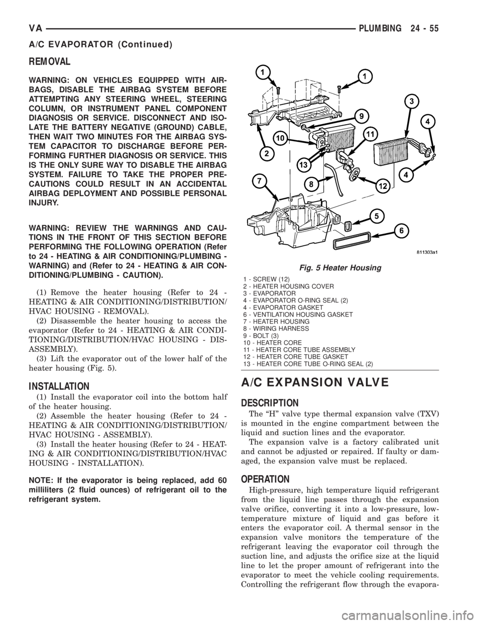
heater housing (Fig. 5).
INSTALLATION
(1) Install the evaporator coil into the bottom half
of the heater housing.
(2) Assemble the heater housing (Refer to 24 -
HEATING & AIR CONDITIONING/DISTRIBUTION/
HVAC HOUSING - ASSEMBLY).
(3) Install the heater housing (Refer to 24 - HEAT-
ING & AIR CONDITIONING/DISTRIBUTION/HVAC
HOUSING - INSTALLATION).
NOTE: If the evaporator is being replaced, add 60
milliliters (2 fluid ounces) of refrigerant oil to the
refrigerant system.
A/C EXPANSION VALVE
DESCRIPTION
The ªHº valve type thermal expansion valve (TXV)
is mounted in the engine compartment between the
liquid and suction lines and the evaporator.
The expansion valve is a factory calibrated unit
and cannot be adjusted or repaired. If faulty or dam-
aged, the expansion valve must be replaced.
OPERATION
High-pressure, high temperature liquid refrigerant
from the liquid line passes through the expansion
valve orifice, converting it into a low-pressure, low-
temperature mixture of liquid and gas before it
enters the evaporator coil. A thermal sensor in the
expansion valve monitors the temperature of the
refrigerant leaving the evaporator coil through the
suction line, and adjusts the orifice size at the liquid
line to let the proper amount of refrigerant into the
evaporator to meet the vehicle cooling requirements.
Controlling the refrigerant flow through the evapora-
Fig. 5 Heater Housing
1 - SCREW (12)
2 - HEATER HOUSING COVER
3 - EVAPORATOR
4 - EVAPORATOR O-RING SEAL (2)
4 - EVAPORATOR GASKET
6 - VENTILATION HOUSING GASKET
7 - HEATER HOUSING
8 - WIRING HARNESS
9 - BOLT (3)
10 - HEATER CORE
11 - HEATER CORE TUBE ASSEMBLY
12 - HEATER CORE TUBE GASKET
13 - HEATER CORE TUBE O-RING SEAL (2)
VAPLUMBING 24 - 55
A/C EVAPORATOR (Continued)
Page 1192 of 1232
RECEIVER/DRIER
DESCRIPTION
The receiver/drier is mounted in a bracket secured
to the left front strut tower in the engine compart-
ment. The receiver/drier is connected between the
front and rear sections of the liquid line between the
condenser outlet and the evaporator inlet. The receiv-
er/drier cannot be repaired. If the receiver/drier is
faulty or damaged, or if the refrigerant system has
been contaminated or left open to the atmosphere for
an indeterminable period or if the compressor has
failed, it must be replaced.
OPERATION
The receiver/drier performs a filtering action to
prevent foreign material in the refrigerant from con-
taminating the expansion valve. A desiccant bag is
mounted inside the receiver/drier canister to absorb
any moisture which may have entered and become
trapped within the refrigerant system. In addition,
during periods of high demand air conditioner opera-
tion, the receiver/drier acts as a reservoir to store
surplus refrigerant. Refrigerant enters the receiver/
drier as a high-pressure, low-temperature liquid.
REMOVAL
WARNING: REVIEW THE WARNINGS AND CAU-
TIONS IN THE FRONT OF THIS SECTION BEFORE
PERFORMING THE FOLLOWING OPERATION (Refer
to 24 - HEATING & AIR CONDITIONING/PLUMBING -
WARNING) and (Refer to 24 - HEATING & AIR CON-
DITIONING/PLUMBING - CAUTION).
(1) Recover the refrigerant from the refrigerant
system(Refer to 24 - HEATING & AIR CONDITION-
ING/PLUMBING - STANDARD PROCEDURE).
(2) Remove the bolts that secure the front and rear
sections of the liquid line to the top of the receiver/
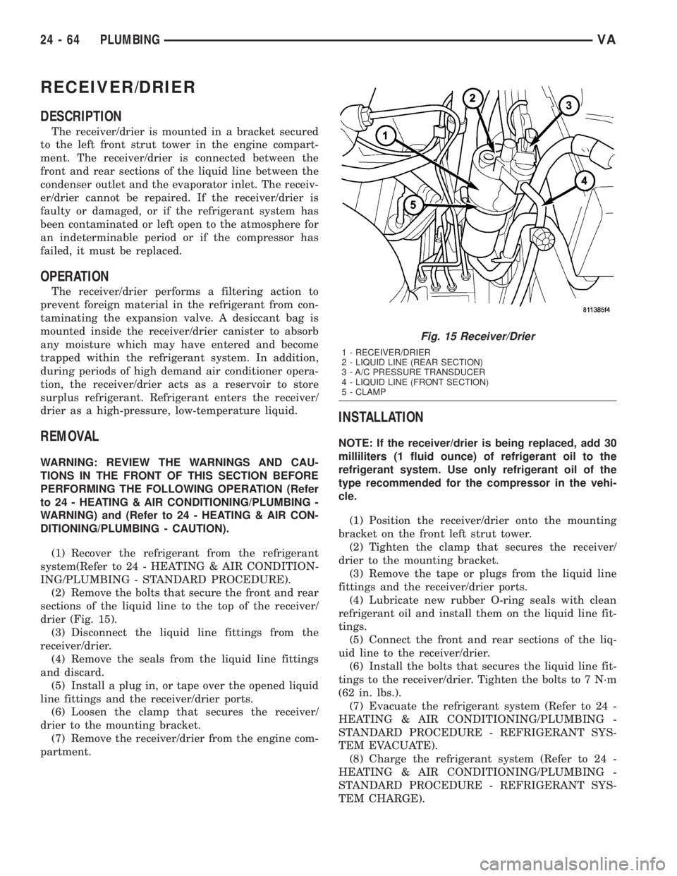
drier (Fig. 15).
(3) Disconnect the liquid line fittings from the
receiver/drier.
(4) Remove the seals from the liquid line fittings
and discard.
(5) Install a plug in, or tape over the opened liquid
line fittings and the receiver/drier ports.
(6) Loosen the clamp that secures the receiver/
drier to the mounting bracket.
(7) Remove the receiver/drier from the engine com-
partment.
INSTALLATION
NOTE: If the receiver/drier is being replaced, add 30
milliliters (1 fluid ounce) of refrigerant oil to the
refrigerant system. Use only refrigerant oil of the
type recommended for the compressor in the vehi-
cle.
(1) Position the receiver/drier onto the mounting
bracket on the front left strut tower.
(2) Tighten the clamp that secures the receiver/
drier to the mounting bracket.
(3) Remove the tape or plugs from the liquid line
fittings and the receiver/drier ports.
(4) Lubricate new rubber O-ring seals with clean
refrigerant oil and install them on the liquid line fit-
tings.
(5) Connect the front and rear sections of the liq-
uid line to the receiver/drier.
(6) Install the bolts that secures the liquid line fit-
tings to the receiver/drier. Tighten the bolts to 7 N´m
(62 in. lbs.).
(7) Evacuate the refrigerant system (Refer to 24 -
HEATING & AIR CONDITIONING/PLUMBING -
STANDARD PROCEDURE - REFRIGERANT SYS-
TEM EVACUATE).
(8) Charge the refrigerant system (Refer to 24 -
HEATING & AIR CONDITIONING/PLUMBING -
STANDARD PROCEDURE - REFRIGERANT SYS-
TEM CHARGE).
Fig. 15 Receiver/Drier
1 - RECEIVER/DRIER
2 - LIQUID LINE (REAR SECTION)
3 - A/C PRESSURE TRANSDUCER
4 - LIQUID LINE (FRONT SECTION)
5 - CLAMP
24 - 64 PLUMBINGVA
Page 1193 of 1232
REFRIGERANT
DESCRIPTION
The refrigerant used in this air conditioning sys-
tem is a HydroFluoroCarbon (HFC), type R-134a.
Unlike R-12, which is a ChloroFluoroCarbon (CFC),
R-134a refrigerant does not contain ozone-depleting
chlorine. R-134a refrigerant is a non-toxic, non-flam-
mable, clear, and colorless liquefied gas.
Even though R-134a does not contain chlorine, it
must be reclaimed and recycled just like CFC-type
refrigerants. This is because R-134a is a greenhouse
gas and can contribute to global warming.
OPERATION
R-134a refrigerant is not compatible with R-12
refrigerant in an air conditioning system. Even a
small amount of R-12 added to an R-134a refrigerant
system will cause compressor failure, refrigerant oil
sludge or poor air conditioning system performance.
In addition, the PolyAlkylene Glycol (PAG) synthetic
refrigerant oils used in an R-134a refrigerant system
are not compatible with the mineral-based refriger-
ant oils used in an R-12 refrigerant system.
R-134a refrigerant system service ports, service
tool couplers and refrigerant dispensing bottles have
all been designed with unique fittings to ensure that
an R-134a system is not accidentally contaminated
with the wrong refrigerant (R-12). There are also
labels posted in the engine compartment of the vehi-
cle and on the compressor identifying to service tech-
nicians that the air conditioning system is equipped
with R-134a.
REFRIGERANT OIL
DESCRIPTION
The refrigerant oil used in R-134a refrigerant sys-
tems is a synthetic-based, PolyAlkylene Glycol (PAG),
wax-free lubricant. Mineral-based R-12 refrigerant
oils are not compatible with PAG oils, and should
never be introduced to an R-134a refrigerant system.
There are different PAG oils available, and each
contains a different additive package. The 10PA17
compressor used in this vehicle is designed to use an
ND8 PAG refrigerant oil. Use only refrigerant oil of
this same type to service the refrigerant system.
OPERATION
After performing any refrigerant recovery or recy-
cling operation, always replenish the refrigerant sys-
tem with the same amount of the recommended
refrigerant oil as was removed. Too little refrigerant
oil can cause compressor damage, and too much can
reduce air conditioning system performance.
PAG refrigerant oil is much more hygroscopic than
mineral oil, and will absorb any moisture it comes
into contact with, even moisture in the air. The PAG
oil container should always be kept tightly capped
until it is ready to be used. After use, recap the oil
container immediately to prevent moisture contami-
nation.
STANDARD PROCEDURE - REFRIGERANT OIL
LEVEL
When an air conditioning system is assembled at
the factory, all components except the compressor are
refrigerant oil free. After the refrigerant system has
been charged and operated, the refrigerant oil in the
compressor is dispersed throughout the refrigerant
system. The receiver-drier, evaporator, condenser,
and compressor will each retain a significant amount
of the needed refrigerant oil.
It is important to have the correct amount of oil in
the refrigerant system. This ensures proper lubrica-
tion of the compressor. Too little oil will result in
damage to the compressor. Too much oil will reduce
the cooling capacity of the air conditioning system.
It will not be necessary to check the oil level in the
compressor or to add oil, unless there has been an oil
loss. An oil loss may occur due to a rupture or leak
from a refrigerant line, a connector fitting, a compo-
nent, or a component seal. If a leak occurs, add 30
milliliters (1 fluid ounce) of refrigerant oil to the
refrigerant system after the repair has been made.
Refrigerant oil loss will be evident at the leak point
by the presence of a wet, shiny surface around the
leak.
Refrigerant oil must be added when a receiver/
drier, evaporator coil, or condenser are replaced. See
the Refrigerant Oil Capacities chart. When a com-
pressor is replaced, the refrigerant oil must be
drained from the old compressor and measured.
Drain all of the refrigerant oil from the new compres-
sor, then fill the new compressor with the same
amount of refrigerant oil that was drained out of the
old compressor.
VAPLUMBING 24 - 65