2005 MERCEDES-BENZ SPRINTER suspension
[x] Cancel search: suspensionPage 1 of 1232
GROUP TAB LOCATOR
Introduction
0Lubrication & Maintenance
2Suspension
3Differential & Driveline
5Brakes
7Cooling
8AAudio/Video
8BChime/Buzzer
8EElectronic Control Modules
8FEngine Systems
8GHeated Systems
8HHorn
8IIgnition Control
8JInstrument Cluster
8LLamps
8NPower Systems
8ORestraints
8PSpeed Control
8QVehicle Theft Security
8RWipers/Washers
8WWiring
9Engine
11Exhaust System
13Frame & Bumpers
14Fuel System
19Steering
21Transmission
22Tires/Wheels
23Body
24Heating & Air Conditioning
25Emissions Control
Component and System Index
Service Manual Comment Forms (Rear of Manual)
Page 15 of 1232
PARTS & LUBRICANT
RECOMMENDATION
STANDARD PROCEDURE - PARTS &
LUBRICANT RECOMMENDATIONS
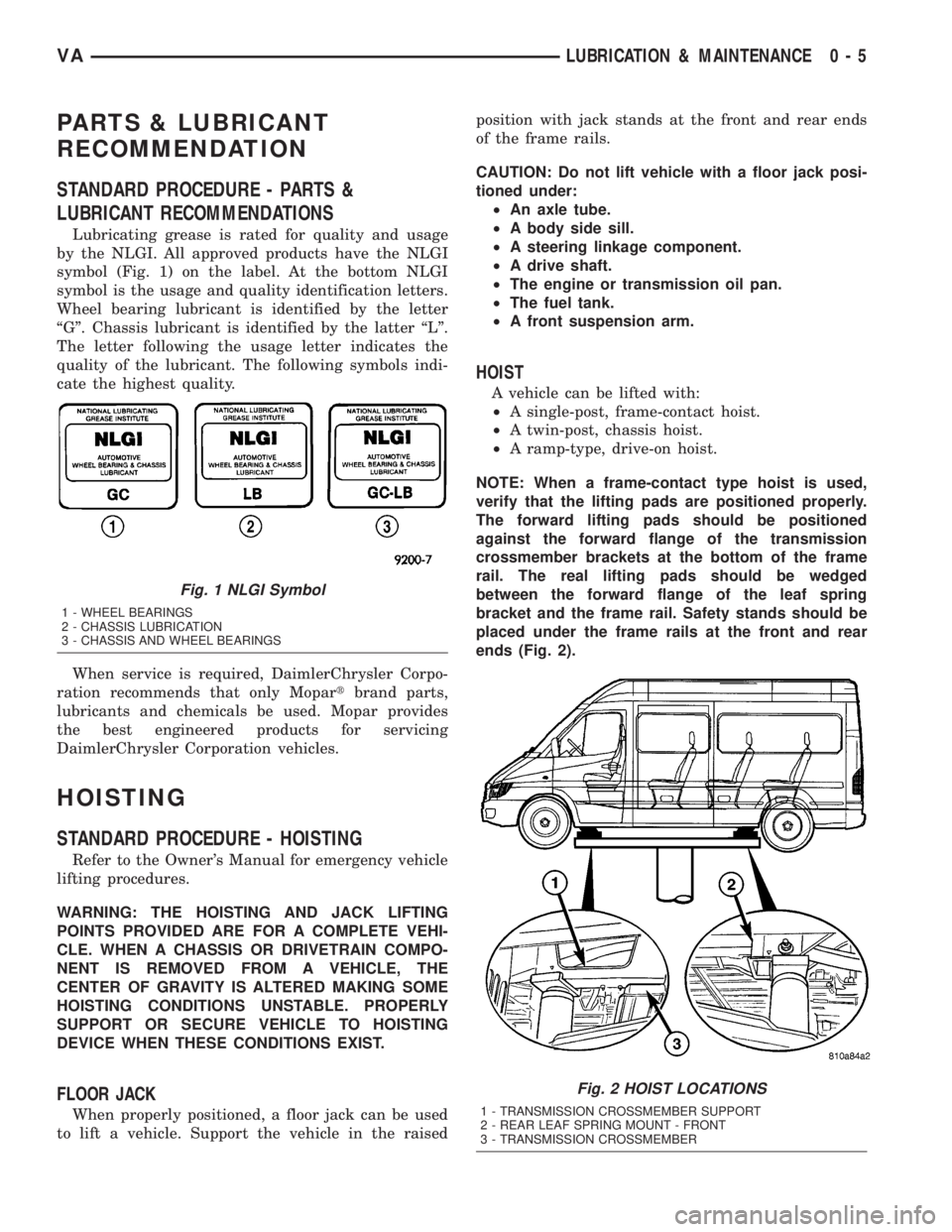
Lubricating grease is rated for quality and usage
by the NLGI. All approved products have the NLGI
symbol (Fig. 1) on the label. At the bottom NLGI
symbol is the usage and quality identification letters.
Wheel bearing lubricant is identified by the letter
ªGº. Chassis lubricant is identified by the latter ªLº.
The letter following the usage letter indicates the
quality of the lubricant. The following symbols indi-
cate the highest quality.
When service is required, DaimlerChrysler Corpo-
ration recommends that only Mopartbrand parts,
lubricants and chemicals be used. Mopar provides
the best engineered products for servicing
DaimlerChrysler Corporation vehicles.
HOISTING
STANDARD PROCEDURE - HOISTING
Refer to the Owner's Manual for emergency vehicle
lifting procedures.
WARNING: THE HOISTING AND JACK LIFTING
POINTS PROVIDED ARE FOR A COMPLETE VEHI-
CLE. WHEN A CHASSIS OR DRIVETRAIN COMPO-
NENT IS REMOVED FROM A VEHICLE, THE
CENTER OF GRAVITY IS ALTERED MAKING SOME
HOISTING CONDITIONS UNSTABLE. PROPERLY
SUPPORT OR SECURE VEHICLE TO HOISTING
DEVICE WHEN THESE CONDITIONS EXIST.
FLOOR JACK
When properly positioned, a floor jack can be used
to lift a vehicle. Support the vehicle in the raisedposition with jack stands at the front and rear ends
of the frame rails.
CAUTION: Do not lift vehicle with a floor jack posi-
tioned under:
²An axle tube.
²A body side sill.
²A steering linkage component.
²A drive shaft.
²The engine or transmission oil pan.
²The fuel tank.
²A front suspension arm.
HOIST
A vehicle can be lifted with:
²A single-post, frame-contact hoist.
²A twin-post, chassis hoist.
²A ramp-type, drive-on hoist.
NOTE: When a frame-contact type hoist is used,
verify that the lifting pads are positioned properly.
The forward lifting pads should be positioned
against the forward flange of the transmission
crossmember brackets at the bottom of the frame
rail. The real lifting pads should be wedged
between the forward flange of the leaf spring
bracket and the frame rail. Safety stands should be
placed under the frame rails at the front and rear
ends (Fig. 2).
Fig. 1 NLGI Symbol
1 - WHEEL BEARINGS
2 - CHASSIS LUBRICATION
3 - CHASSIS AND WHEEL BEARINGS
Fig. 2 HOIST LOCATIONS
1 - TRANSMISSION CROSSMEMBER SUPPORT
2 - REAR LEAF SPRING MOUNT - FRONT
3 - TRANSMISSION CROSSMEMBER
VALUBRICATION & MAINTENANCE 0 - 5
Page 18 of 1232
MAINTENANCE - WITH ASSYST MAINTENANCE
COMPUTER
ASSYST provides information on the best possible
timing for maintenance work.
NOTE: The engine manufacturer strongly recom-
mends the use of synthetic engine oils, such as
TMobil 1 SAE 0W-40.
When the next maintenance service is due, this
will be indicated in the multi-function display with
the wrench icon symbol displayed in km/miles or
days.
²One wrench icon showing indicates Oil Service
is necessary.
²Two wrench icons showing indicates Mainte-
nance Service is necessary ± displayed in km/miles or
days.
If the display shows the number of days, a clock
symbol will also appear in the multi-function display.
You should have the maintenance performed
within the stated period/distance.
The service indicator should be reset after an oil
service and/or maintenance service has been per-
formed.
REGULAR CHECK-UPS
To maintain the safe operation of the vehicle, it is
recommended that the following tasks be performed
on a regular basis (i.e. weekly or whenever the vehi-
cle is refueled). Check:
²Engine oil level
²Brake system, clutch mechanism ± fluid level
²Battery ± acid level
²Windshield washer system and headlamp clean-
ing system ± fluid level
²Mechanical assemblies (e. g. engine, transmis-
sion, etc.) ± check for leaks
²Condition of tires and tires pressures
²All exterior lights
SPECIAL MAINTENANCE REQUIREMENTS
If bodies built by manufacturers other than
DaimlerChrysler Corporation are fitted to the vehi-
cle, the maintenance requirements and lubrication
intervals specified by the body manufacturer must be
adhered to, in addition to all standard maintenance
requirements.
Brake Fluid
Only use brake fluids approved by the manufac-
turer (DOT 4 plus).
Coolant
Corrosion inhibitor/antifreeze concentration in the
coolant should be checked before the onset of winter
(once year in countries with high prevailing temper-
atures).Replace the coolant every five years or 100,000
miles.
Dust Filter for Heating/Ventilation Replace-
ment
The dust filter and the tailgate interior filter are to
be renewed during routine maintenance service. If
operating conditions are dusty, these filters should be
renewed more frequently.
ENGINE OIL CHANGE AND FILTER REPLACEMENT
At the minimum, change the engine oil and oil fil-
ter once a year ± even if the vehicle mileage per year
is extremely low. For standard oil service schedules
refer to the chapter oil service and maintenance ser-
vice.
Once a Year
Select the viscosity of the engine oil (SAE classes)
according to the outside air temperature.
Only use engine oil approved by DaimlerChrysler
Corporation if following the ASSYST system guide-
lines.
If the fuel used has a sulphur content exceeding
0.05% by weight, the service intervals should be split
in half.
SCOPE OF WORK FOR MAINTENANCE SERVICE
Oil Service
²Engine:
Oil change and filter replacement
Check fluid levels of the following system,
refill as necessary.
²If fluid is lost, trace and eliminate cause ± as a
separate order.
²Power-assisted steering
Lubrication work:
²Trailer tow hitch (original equipment)
Maintenance
²ASSYST maintenance computer reset
Function check
²Signalling system, warning and indicator lamps
²Headlamps, exterior lighting
²Windshield wipers, windshield washer system
Check for leaks and damage.
²Check for abrasion points and ensure that lines
are correctly routed!
²All lines and hoses, sensor cables
²Rubber boots on front axle drive shafts, rubber
boots on front axle suspension ball joints, shock
absorbers
Check fluid levels for the following systems,
correct as necessary.
NOTE: Should there be a loss of fluid which cannot
be explained by regular use, trace and eliminate the
cause.
0 - 8 LUBRICATION & MAINTENANCEVA
MAINTENANCE SCHEDULES (Continued)
Page 21 of 1232
SUSPENSION
TABLE OF CONTENTS
page page
FRONT.................................1
REAR.................................11WHEEL ALIGNMENT.....................17
FRONT
TABLE OF CONTENTS
page page
FRONT
SPECIFICATIONS - TORQUE CHART.........2
SPECIAL TOOLS
FRONT SUSPENSION...................2
BUSHINGS
REMOVAL.............................3
INSTALLATION..........................3
HUB / BEARING
DIAGNOSIS AND TESTING -...............4
REMOVAL.............................4
INSTALLATION..........................5
KNUCKLE
REMOVAL.............................5
INSTALLATION..........................5
LOWER BALL JOINT
REMOVAL.............................6
INSTALLATION..........................6
LOWER CONTROL ARM
REMOVAL.............................6
INSTALLATION..........................6SPRING
REMOVAL.............................7
INSTALLATION..........................8
SPRING CLAMP PLATES
REMOVAL.............................8
INSTALLATION..........................8
SPRING STOP PLATES
REMOVAL.............................9
INSTALLATION..........................9
STABILIZER BAR
DESCRIPTION..........................9
OPERATION............................9
REMOVAL.............................9
INSTALLATION..........................9
STABILIZER LINK
REMOVAL.............................9
INSTALLATION..........................9
STRUT
REMOVAL.............................10
INSTALLATION.........................10
VASUSPENSION 2 - 1
Page 22 of 1232
FRONT
SPECIFICATIONS - TORQUE CHART
TORQUE SPECIFICATIONS
DESCRIPTION N´m Ft. Lbs. In. Lbs.
Lower Ball Joint To
Steering Knuckle280 206 Ð
Strut To Steering Knuckle 185 136 Ð
Strut To Body 100 74 Ð
Bottom Spring Clamp
Plate To Front Axle
M12 X 1.5 Bolt130 96 Ð
Bottom Spring Clamp
Plate To Front Axle
M10 Bolt65 48 Ð
Sway Bar Clamp To The
Front Axle30 22 Ð
Hexagon Socket Bolt For
Clamping Nut To Adjust
Wheel Bearing Play12 9 106
Lower Control Arm To
Front Axle Beam150 110 Ð
Stop Plate For Lower
Control Arm60 44 Ð
Outer Tie Rod End Nut 130 96 Ð
Outer Tie Rod End Nut
Jam Nut50 37 Ð
SPECIAL TOOLS
FRONT SUSPENSION
SPECIAL TOOL CROSS REFERENCE CHART
MB
TOOL #MILLER
TOOL #DESCRIPTION
N/A 9288 LEAF SPRING WEDGE
BLOCK
N/A 9294 LOWER BALL JOINT
REMOVE/INSTALLER
N/A 9302 BUSHING REMOVER
/INSTALLER
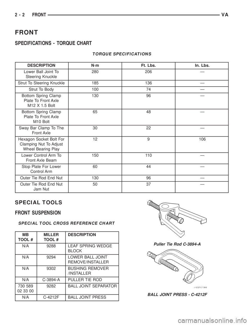
N/A C-3894-A PULLER TIE ROD
730 589
02 33 009282 BALL JOINT SEPARATOR
N/A C-4212F BALL JOINT PRESS
Puller Tie Rod C-3894-A
BALL JOINT PRESS - C-4212F
2 - 2 FRONTVA
Page 23 of 1232
BUSHINGS
REMOVAL
(1) Remove the lower control arm (Refer to 2 -
SUSPENSION/FRONT/LOWER CONTROL ARM -
REMOVAL).
(2) Install the lower control arm in a vise.
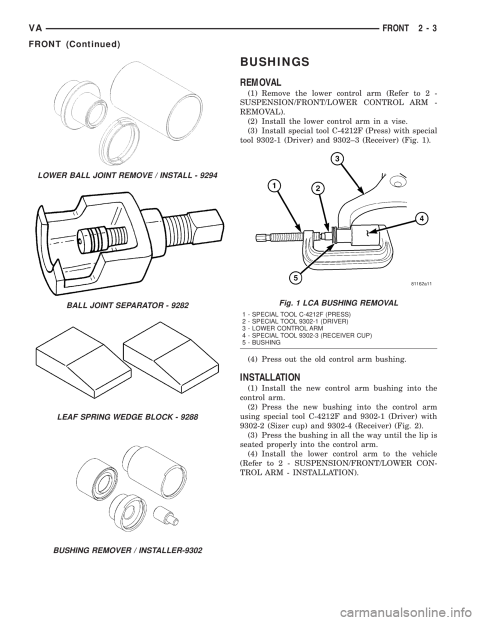
(3) Install special tool C-4212F (Press) with special
tool 9302-1 (Driver) and 9302±3 (Receiver) (Fig. 1).
(4) Press out the old control arm bushing.
INSTALLATION
(1) Install the new control arm bushing into the
control arm.
(2) Press the new bushing into the control arm
using special tool C-4212F and 9302-1 (Driver) with
9302-2 (Sizer cup) and 9302-4 (Receiver) (Fig. 2).
(3) Press the bushing in all the way until the lip is
seated properly into the control arm.
(4) Install the lower control arm to the vehicle
(Refer to 2 - SUSPENSION/FRONT/LOWER CON-
TROL ARM - INSTALLATION).
LOWER BALL JOINT REMOVE / INSTALL - 9294
BALL JOINT SEPARATOR - 9282
LEAF SPRING WEDGE BLOCK - 9288
BUSHING REMOVER / INSTALLER-9302
Fig. 1 LCA BUSHING REMOVAL
1 - SPECIAL TOOL C-4212F (PRESS)
2 - SPECIAL TOOL 9302-1 (DRIVER)
3 - LOWER CONTROL ARM
4 - SPECIAL TOOL 9302-3 (RECEIVER CUP)
5 - BUSHING
VAFRONT 2 - 3
FRONT (Continued)
Page 25 of 1232
INSTALLATION
(1) Install the wheel hub with the tapered roller
bearing on the stub axle (Fig. 4).
(2) Grease the outer tapered roller bearing thor-
oughly and push onto the steering knuckle (Fig. 4).
NOTE: The smooth side of the thrust washer must
point toward the wheel bearing.
(3) Install the thrust washer (Fig. 4).
(4) Install the clamping nut (Fig. 4). Tighten to 12
N´m (9 ft. lbs.) and then loosen a half of a turn.
(5) Check for wheel bearing end play. End play
should be 0.02- 0.04 mm (0.000787 - 0.00158 in.)
(Fig. 3) (Refer to 2 - SUSPENSION/FRONT/HUB /
BEARING - DIAGNOSIS AND TESTING).
(6) Pack the grease cap half with grease and coat
at the edge with sealant and install the cap (Fig. 4).
(7) Install the disc brake rotor (Refer to 5 -
BRAKES/HYDRAULIC/MECHANICAL/ROTORS -
INSTALLATION).
(8) Install the disc brake caliper adapter (Refer to
5 - BRAKES/HYDRAULIC/MECHANICAL/DISC
BRAKE CALIPER ADAPTER - INSTALLATION).
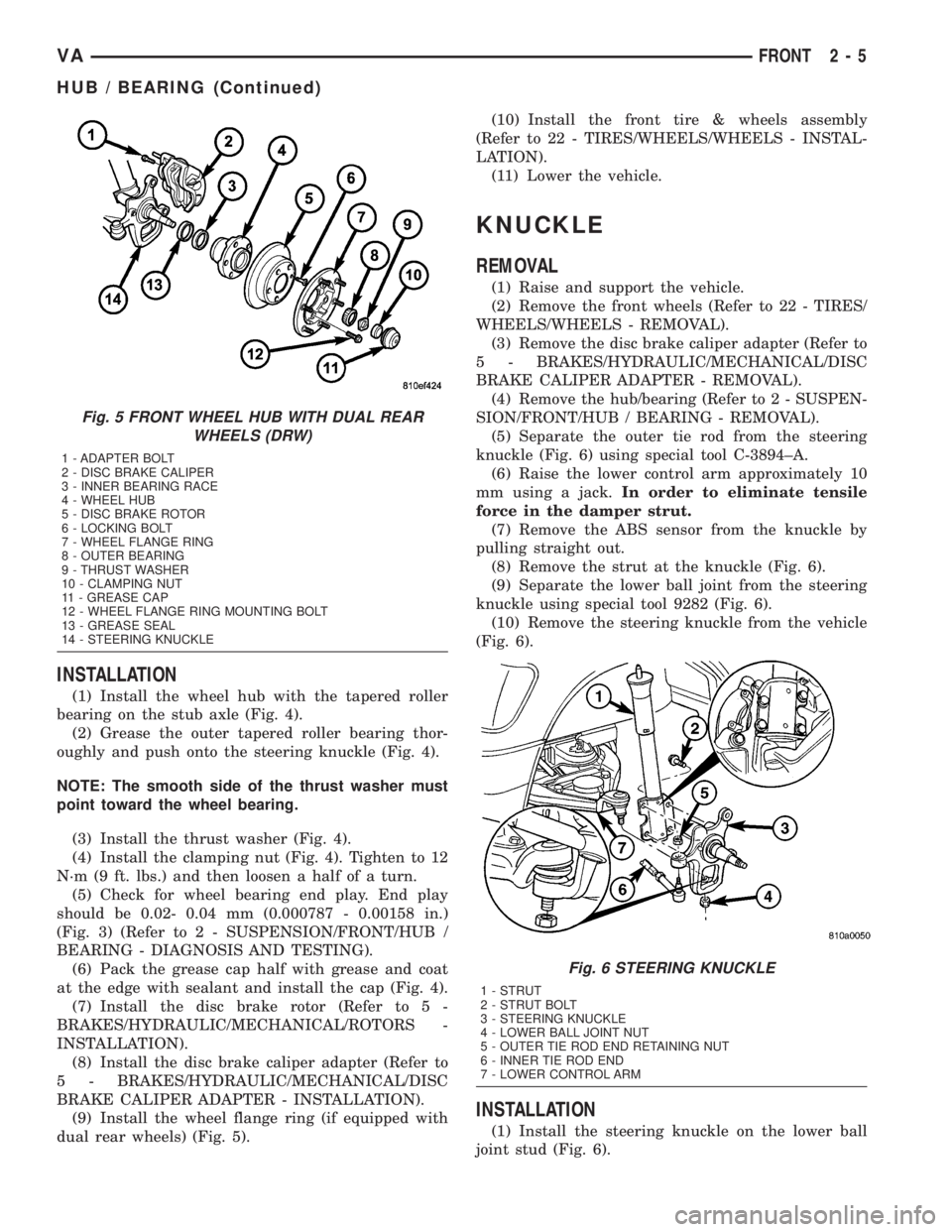
(9) Install the wheel flange ring (if equipped with
dual rear wheels) (Fig. 5).(10) Install the front tire & wheels assembly
(Refer to 22 - TIRES/WHEELS/WHEELS - INSTAL-
LATION).
(11) Lower the vehicle.
KNUCKLE
REMOVAL
(1) Raise and support the vehicle.
(2) Remove the front wheels (Refer to 22 - TIRES/
WHEELS/WHEELS - REMOVAL).
(3) Remove the disc brake caliper adapter (Refer to
5 - BRAKES/HYDRAULIC/MECHANICAL/DISC
BRAKE CALIPER ADAPTER - REMOVAL).
(4) Remove the hub/bearing (Refer to 2 - SUSPEN-
SION/FRONT/HUB / BEARING - REMOVAL).
(5) Separate the outer tie rod from the steering
knuckle (Fig. 6) using special tool C-3894±A.
(6) Raise the lower control arm approximately 10
mm using a jack.In order to eliminate tensile
force in the damper strut.
(7) Remove the ABS sensor from the knuckle by
pulling straight out.
(8) Remove the strut at the knuckle (Fig. 6).
(9) Separate the lower ball joint from the steering
knuckle using special tool 9282 (Fig. 6).
(10) Remove the steering knuckle from the vehicle
(Fig. 6).
INSTALLATION
(1) Install the steering knuckle on the lower ball
joint stud (Fig. 6).
Fig. 5 FRONT WHEEL HUB WITH DUAL REAR
WHEELS (DRW)
1 - ADAPTER BOLT
2 - DISC BRAKE CALIPER
3 - INNER BEARING RACE
4 - WHEEL HUB
5 - DISC BRAKE ROTOR
6 - LOCKING BOLT
7 - WHEEL FLANGE RING
8 - OUTER BEARING
9 - THRUST WASHER
10 - CLAMPING NUT
11 - GREASE CAP
12 - WHEEL FLANGE RING MOUNTING BOLT
13 - GREASE SEAL
14 - STEERING KNUCKLE
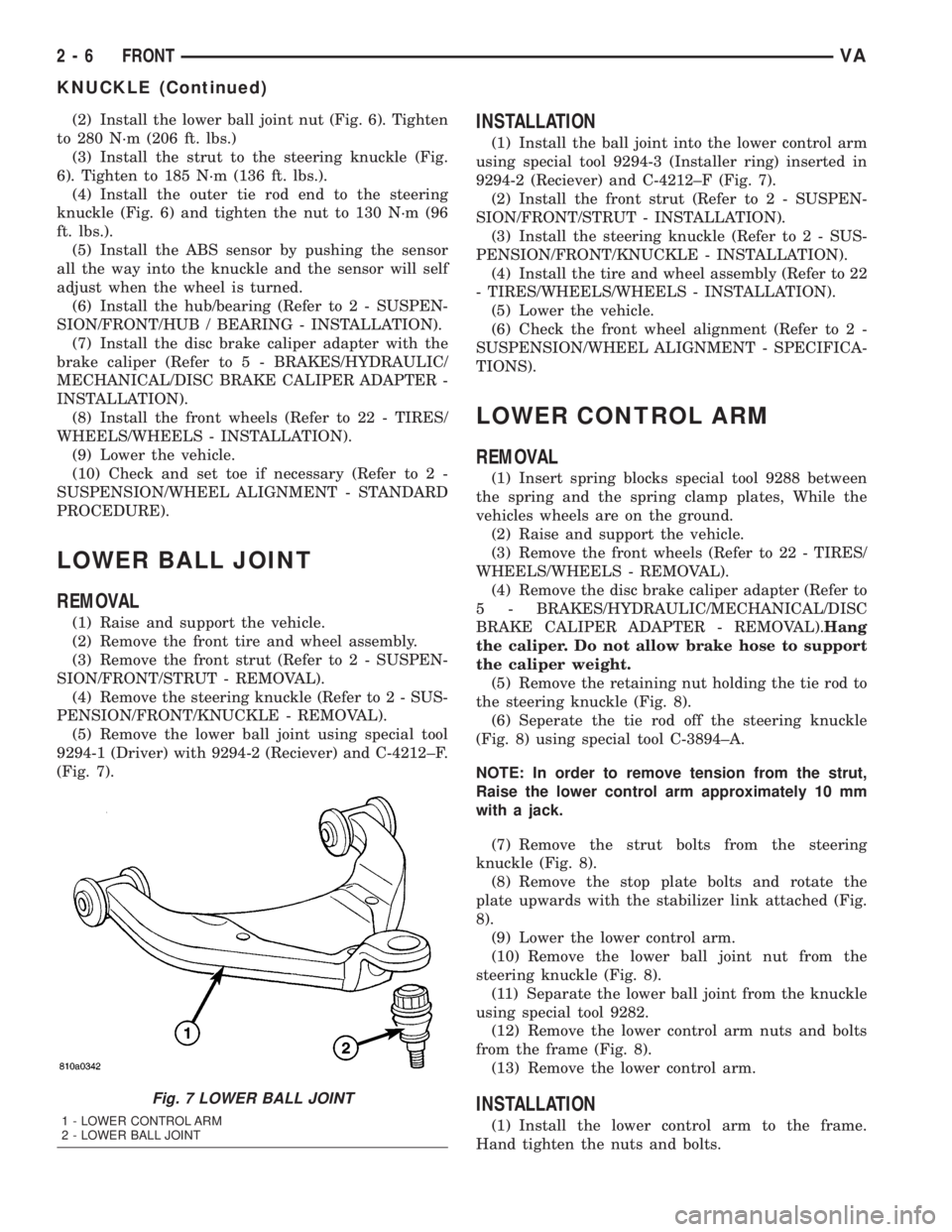
Fig. 6 STEERING KNUCKLE
1 - STRUT
2 - STRUT BOLT
3 - STEERING KNUCKLE
4 - LOWER BALL JOINT NUT
5 - OUTER TIE ROD END RETAINING NUT
6 - INNER TIE ROD END
7 - LOWER CONTROL ARM
VAFRONT 2 - 5
HUB / BEARING (Continued)
Page 26 of 1232
(2) Install the lower ball joint nut (Fig. 6). Tighten
to 280 N´m (206 ft. lbs.)
(3) Install the strut to the steering knuckle (Fig.
6). Tighten to 185 N´m (136 ft. lbs.).
(4) Install the outer tie rod end to the steering
knuckle (Fig. 6) and tighten the nut to 130 N´m (96
ft. lbs.).
(5) Install the ABS sensor by pushing the sensor
all the way into the knuckle and the sensor will self
adjust when the wheel is turned.
(6) Install the hub/bearing (Refer to 2 - SUSPEN-
SION/FRONT/HUB / BEARING - INSTALLATION).
(7) Install the disc brake caliper adapter with the
brake caliper (Refer to 5 - BRAKES/HYDRAULIC/
MECHANICAL/DISC BRAKE CALIPER ADAPTER -
INSTALLATION).
(8) Install the front wheels (Refer to 22 - TIRES/
WHEELS/WHEELS - INSTALLATION).
(9) Lower the vehicle.
(10) Check and set toe if necessary (Refer to 2 -
SUSPENSION/WHEEL ALIGNMENT - STANDARD
PROCEDURE).
LOWER BALL JOINT
REMOVAL
(1) Raise and support the vehicle.
(2) Remove the front tire and wheel assembly.
(3) Remove the front strut (Refer to 2 - SUSPEN-
SION/FRONT/STRUT - REMOVAL).
(4) Remove the steering knuckle (Refer to 2 - SUS-
PENSION/FRONT/KNUCKLE - REMOVAL).
(5) Remove the lower ball joint using special tool
9294-1 (Driver) with 9294-2 (Reciever) and C-4212±F.
(Fig. 7).
INSTALLATION
(1) Install the ball joint into the lower control arm
using special tool 9294-3 (Installer ring) inserted in
9294-2 (Reciever) and C-4212±F (Fig. 7).
(2) Install the front strut (Refer to 2 - SUSPEN-
SION/FRONT/STRUT - INSTALLATION).
(3) Install the steering knuckle (Refer to 2 - SUS-
PENSION/FRONT/KNUCKLE - INSTALLATION).
(4) Install the tire and wheel assembly (Refer to 22
- TIRES/WHEELS/WHEELS - INSTALLATION).
(5) Lower the vehicle.
(6) Check the front wheel alignment (Refer to 2 -
SUSPENSION/WHEEL ALIGNMENT - SPECIFICA-
TIONS).
LOWER CONTROL ARM
REMOVAL
(1) Insert spring blocks special tool 9288 between
the spring and the spring clamp plates, While the
vehicles wheels are on the ground.
(2) Raise and support the vehicle.
(3) Remove the front wheels (Refer to 22 - TIRES/
WHEELS/WHEELS - REMOVAL).
(4) Remove the disc brake caliper adapter (Refer to
5 - BRAKES/HYDRAULIC/MECHANICAL/DISC
BRAKE CALIPER ADAPTER - REMOVAL).Hang
the caliper. Do not allow brake hose to support
the caliper weight.
(5) Remove the retaining nut holding the tie rod to
the steering knuckle (Fig. 8).
(6) Seperate the tie rod off the steering knuckle
(Fig. 8) using special tool C-3894±A.
NOTE: In order to remove tension from the strut,
Raise the lower control arm approximately 10 mm
with a jack.
(7) Remove the strut bolts from the steering
knuckle (Fig. 8).
(8) Remove the stop plate bolts and rotate the
plate upwards with the stabilizer link attached (Fig.
8).
(9) Lower the lower control arm.
(10) Remove the lower ball joint nut from the
steering knuckle (Fig. 8).
(11) Separate the lower ball joint from the knuckle
using special tool 9282.
(12) Remove the lower control arm nuts and bolts
from the frame (Fig. 8).
(13) Remove the lower control arm.
INSTALLATION
(1) Install the lower control arm to the frame.
Hand tighten the nuts and bolts.
Fig. 7 LOWER BALL JOINT
1 - LOWER CONTROL ARM
2 - LOWER BALL JOINT
2 - 6 FRONTVA
KNUCKLE (Continued)