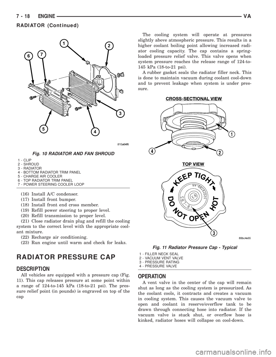
(16) Install A/C condenser.
(17) Install front bumper.
(18) Install front end cross member.
(19) Refill power steering to proper level.
(20) Refill transmission to proper level.
(21) Close radiator drain plug and refill the cooling
system to the correct level with the appropriate cool-
ant mixture.
(22) Recharge air conditioning.
(23) Run engine until warm and check for leaks.
RADIATOR PRESSURE CAP
DESCRIPTION
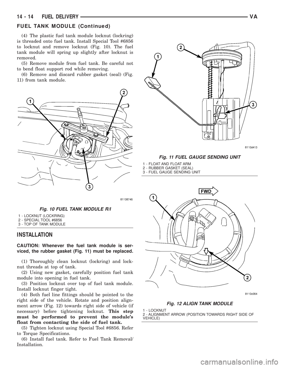
All vehicles are equipped with a pressure cap (Fig.
11). This cap releases pressure at some point within
a range of 124-to-145 kPa (18-to-21 psi). The pres-
sure relief point (in pounds) is engraved on top of the
capThe cooling system will operate at pressures
slightly above atmospheric pressure. This results in a
higher coolant boiling point allowing increased radi-
ator cooling capacity. The cap contains a spring-
loaded pressure relief valve. This valve opens when
system pressure reaches the release range of 124-to-
145 kPa (18-to-21 psi).
A rubber gasket seals the radiator filler neck. This
is done to maintain vacuum during coolant cool-down
and to prevent leakage when system is under pres-
sure.OPERATION
A vent valve in the center of the cap will remain
shut as long as the cooling system is pressurized. As
the coolant cools, it contracts and creates a vacuum
in cooling system. This causes the vacuum valve to
open and coolant in reserve/overflow tank to be
drawn through connecting hose into radiator. If the
vacuum valve is stuck shut, or overflow hose is
kinked, radiator hoses will collapse on cool-down.
Fig. 10 RADIATOR AND FAN SHROUD
1 - CLIP
2 - SHROUD
3 - RADIATOR
4 - BOTTOM RADIATOR TRIM PANEL
5 - CHARGE AIR COOLER
6 - TOP RADIATOR TRIM PANEL
7 - POWER STEERING COOLER LOOP
Fig. 11 Radiator Pressure Cap - Typical
1 - FILLER NECK SEAL
2 - VACUUM VENT VALVE
3 - PRESSURE RATING
4 - PRESSURE VALVE
7 - 18 ENGINEVA
RADIATOR (Continued)
(4) The plastic fuel tank module locknut (lockring)
is threaded onto fuel tank. Install Special Tool #6856
to locknut and remove locknut (Fig. 10). The fuel
tank module will spring up slightly after locknut is
removed.
(5) Remove module from fuel tank. Be careful not
to bend float support rod while removing.
(6) Remove and discard rubber gasket (seal) (Fig.
11) from tank module.
INSTALLATION
CAUTION: Whenever the fuel tank module is ser-
viced, the rubber gasket (Fig. 11) must be replaced.
(1) Thoroughly clean locknut (lockring) and lock-
nut threads at top of tank.
(2) Using new gasket, carefully position fuel tank
module into opening in fuel tank.
(3) Position locknut over top of fuel tank module.
Install locknut finger tight.
(4) Both fuel line fittings should be pointed to the
right side of the vehicle. Rotate and position align-
ment arrow (Fig. 12) towards right side of vehicle (if
necessary) before tightening locknut.This step
must be performed to prevent the module's
float from contacting the side of fuel tank.
(5) Tighten locknut using Special Tool #6856. Refer
to Torque Specifications.
(6) Install fuel tank. Refer to Fuel Tank Removal/
Installation.
Fig. 10 FUEL TANK MODULE R/I
1 - LOCKNUT (LOCKRING)
2 - SPECIAL TOOL #6856
3 - TOP OF TANK MODULE
Fig. 11 FUEL GAUGE SENDING UNIT
1 - FLOAT AND FLOAT ARM
2 - RUBBER GASKET (SEAL)
3 - FUEL GAUGE SENDING UNIT
Fig. 12 ALIGN TANK MODULE
1 - LOCKNUT
2 - ALIGNMENT ARROW (POSITION TOWARDS RIGHT SIDE OF
VEHICLE)
14 - 14 FUEL DELIVERYVA
FUEL TANK MODULE (Continued)