2005 MERCEDES-BENZ SPRINTER starting system
[x] Cancel search: starting systemPage 11 of 1232
LUBRICATION & MAINTENANCE
TABLE OF CONTENTS
page page
FLUID TYPES
DESCRIPTION
DESCRIPTION - FUEL REQUIREMENTS -
DIESEL ENGINE.......................1
DESCRIPTION - ENGINE COOLANT........1
DESCRIPTION - HOAT COOLANT..........2
DESCRIPTION - AXLE...................3
DESCRIPTION - BRAKE FLUID............3
DESCRIPTION - POWER STEERING FLUID . . 3
DESCRIPTION - ENGINE OIL - DIESEL
ENGINES............................3
DESCRIPTION - AUTOMATIC
TRANSMISSION FLUID - NAG1............4
OPERATION - AUTOMATIC TRANSMISSION
FLUID...............................4
FLUID CAPACITIES
SPECIFICATIONS - FLUID CAPACITIES.......4FLUID FILL/CHECK LOCATIONS
INSPECTION - FLUID FILL/CHECK
LOCATIONS..........................4
PARTS & LUBRICANT RECOMMENDATION
STANDARD PROCEDURE - PARTS &
LUBRICANT RECOMMENDATIONS.........5
HOISTING
STANDARD PROCEDURE - HOISTING........5
JUMP STARTING
STANDARD PROCEDURE - JUMP STARTING . . 6
TOWING
STANDARD PROCEDURE - TOWING.........6
MAINTENANCE SCHEDULES
DESCRIPTION..........................7
INTERNATIONAL SYMBOLS
DESCRIPTION..........................9
FLUID TYPES
DESCRIPTION
DESCRIPTION - FUEL REQUIREMENTS -
DIESEL ENGINE
DESCRIPTION
WARNING: Do not use alcohol or gasoline as a fuel
blending agent. They can be unstable under certain
conditions and hazardous or explosive when mixed
with diesel fuel.
Use good quality diesel fuel from a reputable sup-
plier in your Dodge truck. For most year-round ser-
vice, number 2 diesel fuel meeting ASTM
specification D-975 will provide good performance. If
the vehicle is exposed to extreme cold (below 0ÉF/-
18ÉC), or is required to operate at colder-than-normal
conditions for prolonged periods, use climatized No. 2
diesel fuel or dilute the No. 2 diesel fuel with 50%
No. 1 diesel fuel. This will provide better protection
from fuel gelling or wax-plugging of the fuel filters.
Diesel fuel is seldom completely free of water. To
prevent fuel system trouble, including fuel line freez-
ing in winter, drain the accumulated water from the
fuel/water separator using the fuel/water separator
drain provided. If you buy good-quality fuel and fol-low the cold-weather advice above, fuel conditioners
should not be required in your vehicle. If available in
your area, a high cetane ªpremiumº diesel fuel may
offer improved cold starting and warm-up perfor-
mance.
DESCRIPTION - ENGINE COOLANT
ETHYLENE-GLYCOL MIXTURES
CAUTION: Richer antifreeze mixtures cannot be
measured with normal field equipment and can
cause problems associated with 100 percent ethyl-
ene-glycol.
The required ethylene-glycol (antifreeze) and water
mixture depends upon the climate and vehicle oper-
ating conditions. The recommended mixture of 50/50
ethylene-glycol and water will provide protection
against freezing to -37É C (-34É F). The antifreeze
concentrationmust alwaysbe a minimum of 44 per-
cent, year-round in all climates.If percentage is
lower than 44 percent, engine parts may be
eroded by cavitation, and cooling system com-
ponents may be severely damaged by corrosion.
Maximum protection against freezing is provided
with a 68 percent antifreeze concentration, which
prevents freezing down to -67.7É C (-90É F). A higher
percentage will freeze at a warmer temperature.
Also, a higher percentage of antifreeze can cause the
VALUBRICATION & MAINTENANCE 0 - 1
Page 16 of 1232
JUMP STARTING
STANDARD PROCEDURE - JUMP STARTING
WARNING: REVIEW ALL SAFETY PRECAUTIONS
AND WARNINGS IN THE BATTERY SYSTEM SEC-
TION OF THE SERVICE MANUAL. (Refer to 8 -
ELECTRICAL/BATTERY SYSTEM/BATTERY - STAN-
DARD PROCEDURE)
²DO NOT JUMP START A FROZEN BATTERY,
PERSONAL INJURY CAN RESULT.
²IF EQUIPPED, DO NOT JUMP START WHEN
MAINTENANCE FREE BATTERY INDICATOR DOT IS
YELLOW OR BRIGHT COLOR.
²DO NOT JUMP START A VEHICLE WHEN THE
BATTERY FLUID IS BELOW THE TOP OF LEAD
PLATES.
²DO NOT ALLOW JUMPER CABLE CLAMPS TO
TOUCH EACH OTHER WHEN CONNECTED TO A
BOOSTER SOURCE.
²DO NOT USE OPEN FLAME NEAR BATTERY.
²REMOVE METALLIC JEWELRY WORN ON
HANDS OR WRISTS TO AVOID INJURY BY ACCI-
DENTAL ARCING OF BATTERY CURRENT.
²WHEN USING A HIGH OUTPUT BOOSTING
DEVICE, DO NOT ALLOW BATTERY VOLTAGE TO
EXCEED 16 VOLTS. REFER TO INSTRUCTIONS
PROVIDED WITH DEVICE BEING USED.
FAILURE TO FOLLOW THESE INSTRUCTIONS MAY
RESULT IN PERSONAL INJURY.
CAUTION: When using another vehicle as a
booster, do not allow vehicles to touch. Electrical
systems can be damaged on either vehicle.
TO JUMP START A DISABLED VEHICLE:
(1) Raise hood on disabled vehicle and visually
inspect engine compartment for:
²Battery cable clamp condition, clean if necessary.
²Frozen battery.
²Yellow or bright color test indicator, if equipped.
²Low battery fluid level.
²Generator drive belt condition and tension.
²Fuel fumes or leakage, correct if necessary.
CAUTION: If the cause of starting problem on dis-
abled vehicle is severe, damage to booster vehicle
charging system can result.
(2) When using another vehicle as a booster
source, park the booster vehicle within cable reach.
Turn off all accessories, set the parking brake, place
the automatic transmission in PARK or the manual
transmission in NEUTRAL and turn the ignition
OFF.(3) On disabled vehicle, place gear selector in park
or neutral and set park brake. Turn off all accesso-
ries.
(4) Connect jumper cables to booster battery. RED
clamp to positive terminal (+). BLACK clamp to neg-
ative terminal (-). DO NOT allow clamps at opposite
end of cables to touch, electrical arc will result.
Review all warnings in this procedure.
(5) On disabled vehicle, connect RED jumper cable
clamp to positive (+) terminal. Connect BLACK
jumper cable clamp to engine ground as close to the
ground cable attaching point as possible.
(6) Start the engine in the vehicle which has the
booster battery, let the engine idle a few minutes,
then start the engine in the vehicle with the dis-
charged battery.
CAUTION: Do not crank starter motor on disabled
vehicle for more than 15 seconds, starter will over-
heat and could fail.
(7) Allow battery in disabled vehicle to charge to
at least 12.4 volts (75% charge) before attempting to
start engine. If engine does not start within 15 sec-
onds, stop cranking engine and allow starter to cool
(15 min.), before cranking again.
DISCONNECT CABLE CLAMPS AS FOLLOWS:
²Disconnect BLACK cable clamp from engine
ground on disabled vehicle.
²When using a Booster vehicle, disconnect
BLACK cable clamp from battery negative terminal.
Disconnect RED cable clamp from battery positive
terminal.
²Disconnect RED cable clamp from battery posi-
tive terminal on disabled vehicle.
TOWING
STANDARD PROCEDURE - TOWING
WARNING: Do not tow the vehicle if the key cannot
be turned in the ignition lock. If the key cannot be
turned, the ignition lock remains locked and the
vehicle cannot be steered. With the engine not run-
ning there is no power assistance for the braking
and steering systems. In this case, it is important to
keep in mind that a considerably higher degree of
effort is necessary to brake and steer the vehicle.
The vehicle must not be towed with the front axle
raised and the key in position 2 in the ignition lock
as the drive wheels could then lock due to the
acceleration skid control (ASR)
0 - 6 LUBRICATION & MAINTENANCEVA
Page 37 of 1232
WHEEL ALIGNMENT
TABLE OF CONTENTS
page page
WHEEL ALIGNMENT
DESCRIPTION.........................17
DIAGNOSIS AND TESTING - PRE-ALIGNMENT
INSPECTION.........................17STANDARD PROCEDURE - TOE
ADJUSTMENT........................19
SPECIFICATIONS.......................19
WHEEL ALIGNMENT
DESCRIPTION
NOTE: Camber and Caster are not adjustable on
this vehicle. (TOE ONLY).
NOTE: Suspension components with rubber/ure-
thane bushings should be tightened with the vehi-
cle at normal ride height. It is important to have the
springs supporting the weight of the vehicle when
the fasteners are torqued. If springs are not at their
normal ride position, vehicle ride comfort could be
affected and premature bushing wear may occur.
Wheel alignment involves the correct positioning of
the wheels in relation to the vehicle. The positioning
is accomplished through suspension and steering
linkage adjustments. An alignment is considered
essential for efficient steering, good directional stabil-
ity and to minimize tire wear. The most important
measurements of an alignment are caster, camber
and toe (Fig. 1).
CAUTION: Never attempt to modify suspension or
steering components by heating or bending.
DIAGNOSIS AND TESTING - PRE-ALIGNMENT
INSPECTION
Before starting wheel alignment, the following
inspection and necessary corrections must be com-
pleted. Refer to Suspension and Steering System
Diagnosis Chart below for additional information.(1) Inspect tires for size, air pressure and tread
wear.
(2) Inspect front wheel bearings for wear.
(3) Inspect front wheels for excessive radial or lat-
eral runout and balance.
(4) Inspect ball studs, linkage pivot points and
steering gear for looseness, roughness or binding.
(5) Inspect suspension components for wear and
noise.
(6) Road test the vehicle.
Fig. 1 Wheel Alignment Measurements
1 - FRONT OF VEHICLE
2 - STEERING AXIS INCLINATION
3 - PIVOT POINT
4 - TOE-IN
VAWHEEL ALIGNMENT 2 - 17
Page 129 of 1232
ENGINE SYSTEMS
TABLE OF CONTENTS
page page
BATTERY SYSTEM......................... 1
CHARGING SYSTEM....................... 17STARTING SYSTEM....................... 24
BATTERY SYSTEM
TABLE OF CONTENTS
page page
BATTERY SYSTEM
DESCRIPTION..........................1
OPERATION............................2
DIAGNOSIS AND TESTING - BATTERY
SYSTEM.............................2
CLEANING.............................5
INSPECTION...........................6
SPECIAL TOOLS
BATTERY SYSTEM SPECIAL TOOLS.......6
BATTERY
DESCRIPTION..........................6
OPERATION............................7
DIAGNOSIS AND TESTING - BATTERY.......7
STANDARD PROCEDURE
STANDARD PROCEDURE - BATTERY
CHARGING...........................8
STANDARD PROCEDURE - OPEN-CIRCUIT
VOLTAGE TEST.......................10
STANDARD PROCEDURE - IGNITION-OFF
DRAW TEST.........................10
STANDARD PROCEDURE - USING MICRO
420 BATTERY TESTER.................11
STANDARD PROCEDURE - CHECKING
BATTERY ELECTROLYTE LEVEL.........12REMOVAL
UNDER HOOD BATTERY REMOVAL.......12
AUXILIARY BATTERY REMOVAL..........13
INSTALLATION
UNDER HOOD BATTERY INSTALLATION . . . 13
AUXILIARY BATTERY INSTALLATION......13
BATTERY HOLDDOWN
DESCRIPTION.........................14
REMOVAL.............................14
INSTALLATION.........................14
BATTERY CABLES
DESCRIPTION.........................14
OPERATION...........................14
DIAGNOSIS AND TESTING - BATTERY
CABLES............................14
REMOVAL.............................16
INSTALLATION.........................16
BATTERY TRAY
DESCRIPTION.........................16
OPERATION...........................16
REMOVAL.............................16
INSTALLATION.........................16
BATTERY SYSTEM
DESCRIPTION
A single 12-volt battery is standard factory-in-
stalled equipment on this model. Some vehicles are
equipped with a second auxiliary battery for running
additional electrical equipment. The standard battery
is located in the engine compartment, while the aux-
iliary battery (if equipped) is located under the pas-
sengers front seat. The battery system for thisvehicle covers the following related components,
which are covered in further detail later in this sec-
tion of the service manual:
²Battery- The 12v storage battery(s) provides a
reliable means of storing a renewable source of elec-
trical energy within the vehicle.
²Battery Cables- The battery cables connect
the battery terminal posts to the vehicle electrical
system.
VAENGINE SYSTEMS 8F - 1
Page 130 of 1232
²Battery Holddown- The battery holddown
hardware secures the battery in the battery tray in
the engine compartment.
²Battery Tray- The battery tray provides a
secure mounting location in the vehicle for the bat-
tery and an anchor point for the battery holddown
hardware.
For battery system maintenance schedules and
jump starting procedures, see the owner's manual in
the vehicle glove box. Optionally, refer to the Lubri-
cation and Maintenance section of this manual for
the recommended battery maintenance schedules and
for the proper battery jump starting procedure. While
battery charging can be considered a maintenance
procedure, the battery charging procedure and
related information are located later in this section of
this service manual. This was done because the bat-
tery must be fully-charged before any battery system
diagnosis or testing procedures can be performed.
OPERATION
The battery system is designed to provide a safe,
efficient, reliable and mobile means of delivering and
storing electrical energy. This electrical energy is
required to operate the engine starting system, as
well as to operate many of the other vehicle acces-
sory systems for limited durations while the engine
and/or the charging system are not operating. The
battery system is also designed to provide a reserve
of electrical energy to supplement the charging sys-
tem for short durations while the engine is running
and the electrical current demands of the vehicle
exceed the output of the charging system. In addition
to delivering, and storing electrical energy for the
vehicle, the battery system serves as a capacitor and
voltage stabilizer for the vehicle electrical system. It
absorbs most abnormal or transient voltages caused
by the switching of any of the electrical components
or circuits in the vehicle.
DIAGNOSIS AND TESTING - BATTERY SYSTEM
The battery, starting, and charging systems in the
vehicle operate with one another and must be testedas a complete system. In order for the engine to start
and the battery to maintain its charge properly, all of
the components that are used in these systems must
perform within specifications. It is important that
the battery, starting, and charging systems be thor-
oughly tested and inspected any time a battery needs
to be charged or replaced. The cause of abnormal bat-
tery discharge, overcharging or early battery failure
must be diagnosed and corrected before a battery is
replaced and before a vehicle is returned to service.
The service information for these systems has been
separated within this service manual to make it eas-
ier to locate the specific information you are seeking.
However, when attempting to diagnose any of these
systems, it is important that you keep their interde-
pendency in mind.
The diagnostic procedures used for the battery,
starting, and charging systems include the most
basic conventional diagnostic methods, to the more
sophisticated On-Board Diagnostics (OBD) built into
the Powertrain Control Module (PCM). Use of an
induction-type milliampere ammeter, a volt/ohmme-
ter, a battery charger, a carbon pile rheostat (load
tester) and a 12-volt test lamp may be required. All
OBD-sensed systems are monitored by the PCM.
Each monitored circuit is assigned a Diagnostic Trou-
ble Code (DTC). The PCM will store a DTC in elec-
tronic memory for any failure it detects. Refer to
Charging System for the proper charging system on-
board diagnostic test procedures.
MICRO 420 BATTERY TESTER
The Micro 420 automotive battery tester is
designed to help the dealership technicians diagnose
the cause of a defective battery. Follow the instruc-
tion manual supplied with the tester to properly
diagnose a vehicle. If the instruction manual is not
available refer to the standard procedure in this sec-
tion, which includes the directions for using the
Micro 420 battery tester.
8F - 2 BATTERY SYSTEMVA
BATTERY SYSTEM (Continued)
Page 131 of 1232
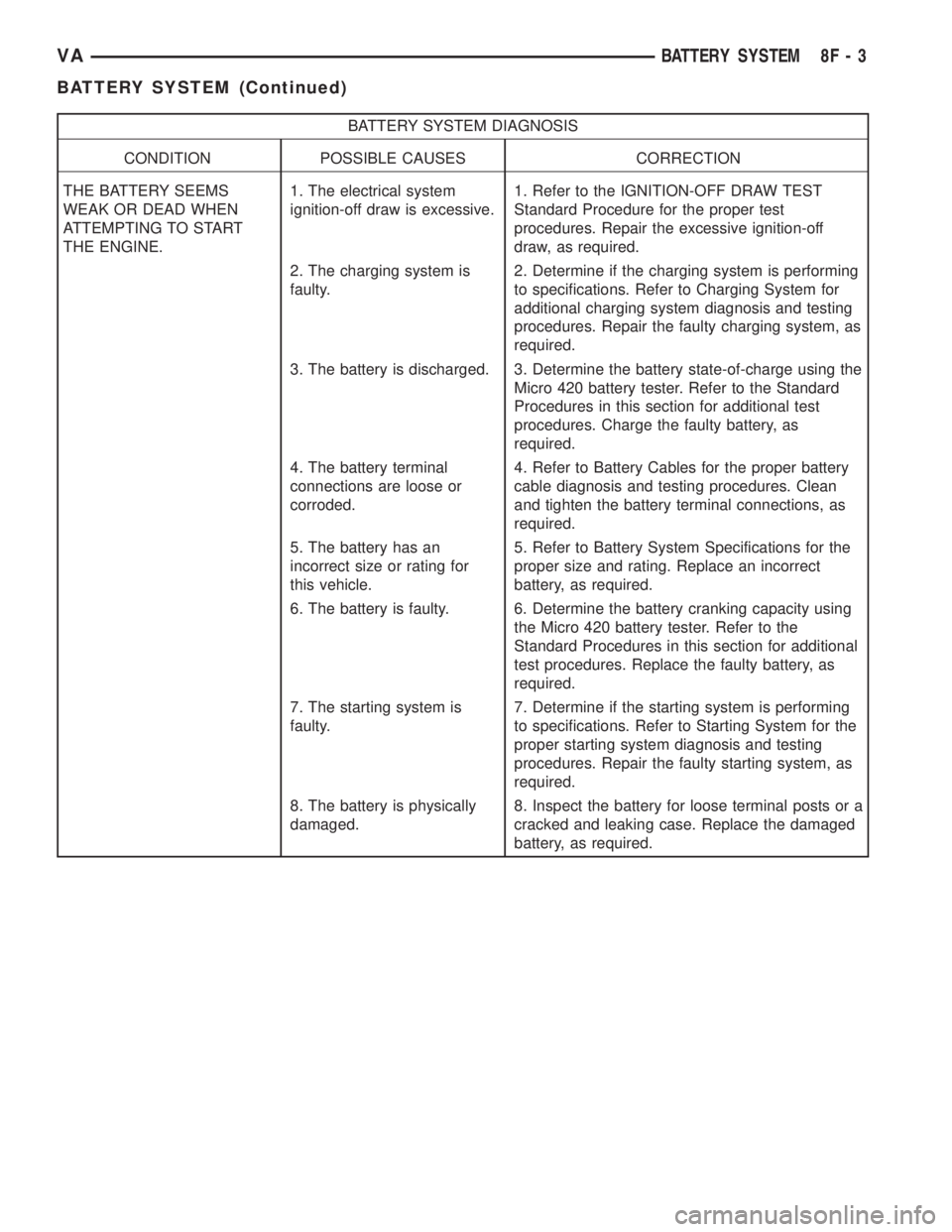
BATTERY SYSTEM DIAGNOSIS
CONDITION POSSIBLE CAUSES CORRECTION
THE BATTERY SEEMS
WEAK OR DEAD WHEN
ATTEMPTING TO START
THE ENGINE.1. The electrical system
ignition-off draw is excessive.1. Refer to the IGNITION-OFF DRAW TEST
Standard Procedure for the proper test
procedures. Repair the excessive ignition-off
draw, as required.
2. The charging system is
faulty.2. Determine if the charging system is performing
to specifications. Refer to Charging System for
additional charging system diagnosis and testing
procedures. Repair the faulty charging system, as
required.
3. The battery is discharged. 3. Determine the battery state-of-charge using the
Micro 420 battery tester. Refer to the Standard
Procedures in this section for additional test
procedures. Charge the faulty battery, as
required.
4. The battery terminal
connections are loose or
corroded.4. Refer to Battery Cables for the proper battery
cable diagnosis and testing procedures. Clean
and tighten the battery terminal connections, as
required.
5. The battery has an
incorrect size or rating for
this vehicle.5. Refer to Battery System Specifications for the
proper size and rating. Replace an incorrect
battery, as required.
6. The battery is faulty. 6. Determine the battery cranking capacity using
the Micro 420 battery tester. Refer to the
Standard Procedures in this section for additional
test procedures. Replace the faulty battery, as
required.
7. The starting system is
faulty.7. Determine if the starting system is performing
to specifications. Refer to Starting System for the
proper starting system diagnosis and testing
procedures. Repair the faulty starting system, as
required.
8. The battery is physically
damaged.8. Inspect the battery for loose terminal posts or a
cracked and leaking case. Replace the damaged
battery, as required.
VABATTERY SYSTEM 8F - 3
BATTERY SYSTEM (Continued)
Page 132 of 1232
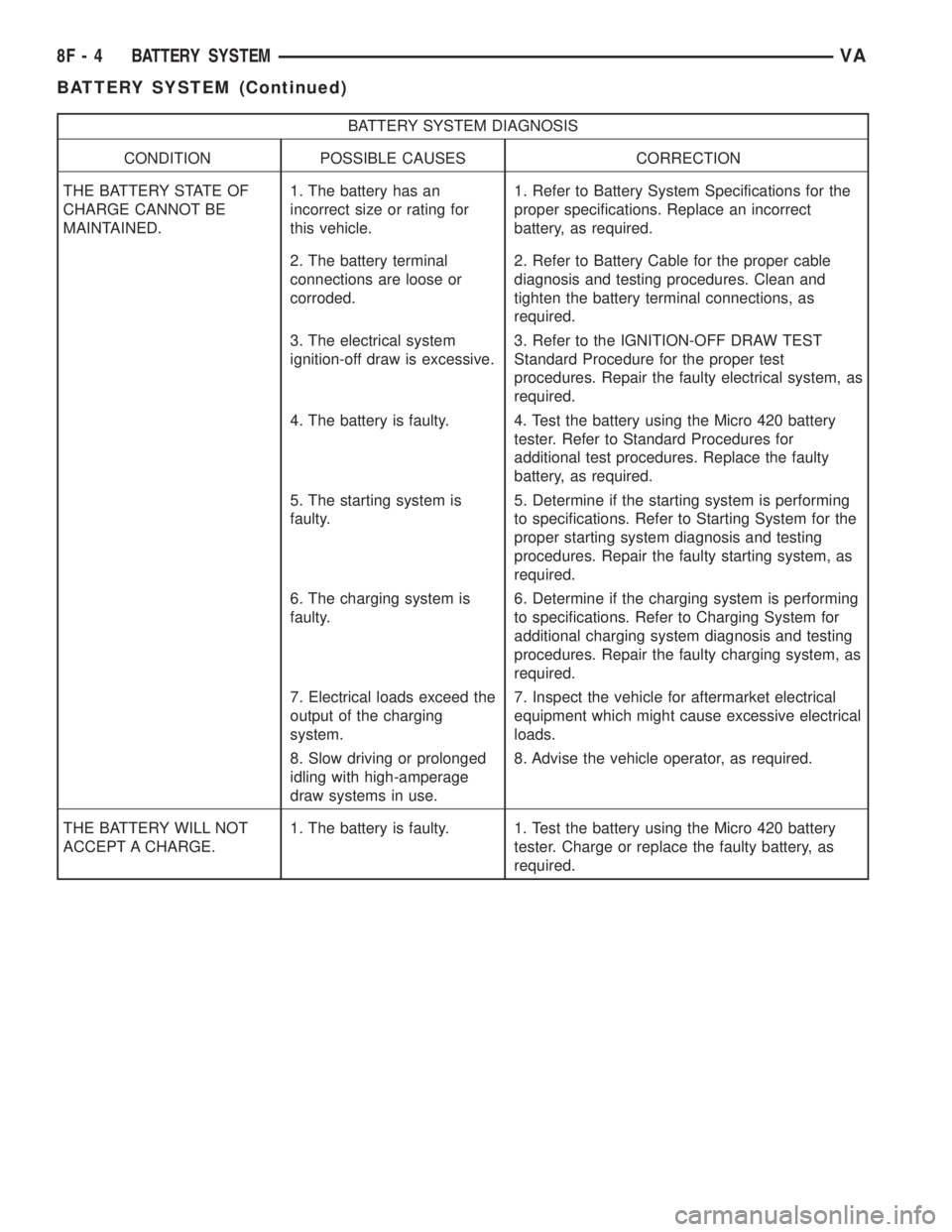
BATTERY SYSTEM DIAGNOSIS
CONDITION POSSIBLE CAUSES CORRECTION
THE BATTERY STATE OF
CHARGE CANNOT BE
MAINTAINED.1. The battery has an
incorrect size or rating for
this vehicle.1. Refer to Battery System Specifications for the
proper specifications. Replace an incorrect
battery, as required.
2. The battery terminal
connections are loose or
corroded.2. Refer to Battery Cable for the proper cable
diagnosis and testing procedures. Clean and
tighten the battery terminal connections, as
required.
3. The electrical system
ignition-off draw is excessive.3. Refer to the IGNITION-OFF DRAW TEST
Standard Procedure for the proper test
procedures. Repair the faulty electrical system, as
required.
4. The battery is faulty. 4. Test the battery using the Micro 420 battery
tester. Refer to Standard Procedures for
additional test procedures. Replace the faulty
battery, as required.
5. The starting system is
faulty.5. Determine if the starting system is performing
to specifications. Refer to Starting System for the
proper starting system diagnosis and testing
procedures. Repair the faulty starting system, as
required.
6. The charging system is
faulty.6. Determine if the charging system is performing
to specifications. Refer to Charging System for
additional charging system diagnosis and testing
procedures. Repair the faulty charging system, as
required.
7. Electrical loads exceed the
output of the charging
system.7. Inspect the vehicle for aftermarket electrical
equipment which might cause excessive electrical
loads.
8. Slow driving or prolonged
idling with high-amperage
draw systems in use.8. Advise the vehicle operator, as required.
THE BATTERY WILL NOT
ACCEPT A CHARGE.1. The battery is faulty. 1. Test the battery using the Micro 420 battery
tester. Charge or replace the faulty battery, as
required.
8F - 4 BATTERY SYSTEMVA
BATTERY SYSTEM (Continued)
Page 133 of 1232
ABNORMAL BATTERY DISCHARGING
Any of the following conditions can result in abnor-
mal battery discharging:
1. A faulty or incorrect charging system compo-
nent. Refer to Charging System for additional charg-
ing system diagnosis and testing procedures.
2. A faulty or incorrect battery. Use Micro 420 bat-
tery tester and refer to Battery System for additional
battery diagnosis and testing procedures.
3. A faulty circuit or component causing excessive
ignition-off draw.
4. Electrical loads that exceed the output of the
charging system. This can be due to equipment
installed after manufacture, or repeated short trip
use.
5. A faulty or incorrect starting system component.
Refer to Starting System for the proper starting sys-
tem diagnosis and testing procedures.
6. Corroded or loose battery posts and/or terminal
clamps.
7. Slow driving speeds (heavy traffic conditions) or
prolonged idling, with high-amperage draw systems
in use.
CLEANING
The following information details the recommended
cleaning procedures for the battery and related com-
ponents. In addition to the maintenance schedules
found in this service manual and the owner's man-
ual, it is recommended that these procedures be per-
formed any time the battery or related components
must be removed for vehicle service.
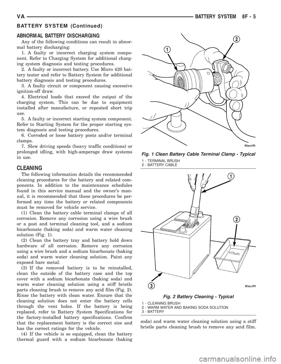
(1) Clean the battery cable terminal clamps of all
corrosion. Remove any corrosion using a wire brush
or a post and terminal cleaning tool, and a sodium
bicarbonate (baking soda) and warm water cleaning
solution (Fig. 1).
(2) Clean the battery tray and battery hold down
hardware of all corrosion. Remove any corrosion
using a wire brush and a sodium bicarbonate (baking
soda) and warm water cleaning solution. Paint any
exposed bare metal.
(3) If the removed battery is to be reinstalled,
clean the outside of the battery case and the top
cover with a sodium bicarbonate (baking soda) and
warm water cleaning solution using a stiff bristle
parts cleaning brush to remove any acid film (Fig. 2).
Rinse the battery with clean water. Ensure that the
cleaning solution does not enter the battery cells
through the vent holes. If the battery is being
replaced, refer to Battery System Specifications for
the factory-installed battery specifications. Confirm
that the replacement battery is the correct size and
has the correct ratings for the vehicle.
(4) If the vehicle is so equipped, clean the battery
thermal guard with a sodium bicarbonate (bakingsoda) and warm water cleaning solution using a stiff
bristle parts cleaning brush to remove any acid film.
Fig. 1 Clean Battery Cable Terminal Clamp - Typical
1 - TERMINAL BRUSH
2 - BATTERY CABLE
Fig. 2 Battery Cleaning - Typical
1 - CLEANING BRUSH
2 - WARM WATER AND BAKING SODA SOLUTION
3 - BATTERY
VABATTERY SYSTEM 8F - 5
BATTERY SYSTEM (Continued)