2005 MERCEDES-BENZ SPRINTER AUX
[x] Cancel search: AUXPage 14 of 1232
Full synthetic oils, such as Mobilt1 0W-40, is
required if the ASSYST Oil Service Reminder is fol-
lowed. Use of a lower quality oil on this service
schedule may cause severe engine damage.
DESCRIPTION - AUTOMATIC TRANSMISSION
FLUID - NAG1
NOTE: Refer to Service Procedures in this group for
fluid level checking procedures.
Shellt3403 Automatic Transmission Fluid is the
recommended fluid for the NAG1 DaimlerChrysler
automatic transmission.
Dexron II fluid IS NOT recommended. Clutch
chatter can result from the use of improper
fluid.
MopartATF+4, Automatic Transmission Fluid, or
other fluids meeting MS-9602, may be used if Shellt
3403 Automatic Transmission Fluid is not available.
Shellt3403 Automatic Transmission Fluid when
new is red in color. The ATF is dyed red so it can be
identified from other fluids used in the vehicle such
as engine oil or antifreeze. The red color is not per-
manent and is not an indicator of fluid condition. As
the vehicle is driven, the ATF will begin to look
darker in color and may eventually become brown.
This is normal.
FLUID ADDITIVES
DaimlerChrysler strongly recommends against the
addition of any fluids to the transmission, other than
those automatic transmission fluids listed above.
Exceptions to this policy are the use of special dyes
to aid in detecting fluid leaks.
Various ªspecialº additives and supplements exist
that claim to improve shift feel and/or quality. These
additives and others also claim to improve converter
clutch operation and inhibit overheating, oxidation,
varnish, and sludge. These claims have not been sup-
ported to the satisfaction of DaimlerChrysler and
these additivesmust not be used.The use of trans-
mission ªsealersº should also be avoided, since they
may adversely affect the integrity of transmission
seals.
OPERATION - AUTOMATIC TRANSMISSION
FLUID
The automatic transmission fluid is selected based
upon several qualities. The fluid must provide a high
level of protection for the internal components by
providing a lubricating film between adjacent metal
components. The fluid must also be thermally stable
so that it can maintain a consistent viscosity through
a large temperature range. If the viscosity stays con-
stant through the temperature range of operation,transmission operation and shift feel will remain con-
sistent. Transmission fluid must also be a good con-
ductor of heat. The fluid must absorb heat from the
internal transmission components and transfer that
heat to the transmission case.
FLUID CAPACITIES
SPECIFICATIONS - FLUID CAPACITIES
DESCRIPTION SPECIFICATION
ENGINE COOLANT
10 Liters 10.5 Quarts
ENGINE OIL
9.0L with Filter
Replacement9.5 Quarts with Filter
Replacement
AUTOMATIC TRANSMISSION
Service Fill - NAG1 5.0 L (10.6 pts.)
O-haul Fill - NAG1 7.7 L (16.3 pts.)
Dry fill capacity Depending on type and size of
internal cooler, length and inside diameter of cooler
lines, or use of an auxiliary cooler, these figures may
vary. (Refer to appropriate 21 - TRANSMISSION/
AUTOMATIC/FLUID - STANDARD PROCEDURE).
REAR AXLE .03L (1 oz.)
8 1/2 1.8 L (4.0 pts.)
FUEL TANK
Primary 100 L (26.4 gal.)*
Reserve 10.5 L (2.8 gal.)*
*Nominal refill capacities are shown. A variation may
be observed from vehicle to vehicle due to
manufacturing tolerance and refill procedure
POWER STEERING SYSTEM
Power steering fluid capacities are dependent on
engine/chassis options as well as steering gear/cooler
options. Depending on type and size of internal
cooler, length and inside diameter of cooler lines, or
use of an auxiliary cooler, these capacities may vary.
Refer to 19, Steering for proper fill and bleed
procedures.
FLUID FILL/CHECK
LOCATIONS
INSPECTION - FLUID FILL/CHECK LOCATIONS
The fluid fill/check locations and lubrication points
are located in each applicable group.
0 - 4 LUBRICATION & MAINTENANCEVA
FLUID TYPES (Continued)
Page 129 of 1232
ENGINE SYSTEMS
TABLE OF CONTENTS
page page
BATTERY SYSTEM......................... 1
CHARGING SYSTEM....................... 17STARTING SYSTEM....................... 24
BATTERY SYSTEM
TABLE OF CONTENTS
page page
BATTERY SYSTEM
DESCRIPTION..........................1
OPERATION............................2
DIAGNOSIS AND TESTING - BATTERY
SYSTEM.............................2
CLEANING.............................5
INSPECTION...........................6
SPECIAL TOOLS
BATTERY SYSTEM SPECIAL TOOLS.......6
BATTERY
DESCRIPTION..........................6
OPERATION............................7
DIAGNOSIS AND TESTING - BATTERY.......7
STANDARD PROCEDURE
STANDARD PROCEDURE - BATTERY
CHARGING...........................8
STANDARD PROCEDURE - OPEN-CIRCUIT
VOLTAGE TEST.......................10
STANDARD PROCEDURE - IGNITION-OFF
DRAW TEST.........................10
STANDARD PROCEDURE - USING MICRO
420 BATTERY TESTER.................11
STANDARD PROCEDURE - CHECKING
BATTERY ELECTROLYTE LEVEL.........12REMOVAL
UNDER HOOD BATTERY REMOVAL.......12
AUXILIARY BATTERY REMOVAL..........13
INSTALLATION
UNDER HOOD BATTERY INSTALLATION . . . 13
AUXILIARY BATTERY INSTALLATION......13
BATTERY HOLDDOWN
DESCRIPTION.........................14
REMOVAL.............................14
INSTALLATION.........................14
BATTERY CABLES
DESCRIPTION.........................14
OPERATION...........................14
DIAGNOSIS AND TESTING - BATTERY
CABLES............................14
REMOVAL.............................16
INSTALLATION.........................16
BATTERY TRAY
DESCRIPTION.........................16
OPERATION...........................16
REMOVAL.............................16
INSTALLATION.........................16
BATTERY SYSTEM
DESCRIPTION
A single 12-volt battery is standard factory-in-
stalled equipment on this model. Some vehicles are
equipped with a second auxiliary battery for running
additional electrical equipment. The standard battery
is located in the engine compartment, while the aux-
iliary battery (if equipped) is located under the pas-
sengers front seat. The battery system for thisvehicle covers the following related components,
which are covered in further detail later in this sec-
tion of the service manual:
²Battery- The 12v storage battery(s) provides a
reliable means of storing a renewable source of elec-
trical energy within the vehicle.
²Battery Cables- The battery cables connect
the battery terminal posts to the vehicle electrical
system.
VAENGINE SYSTEMS 8F - 1
Page 134 of 1232
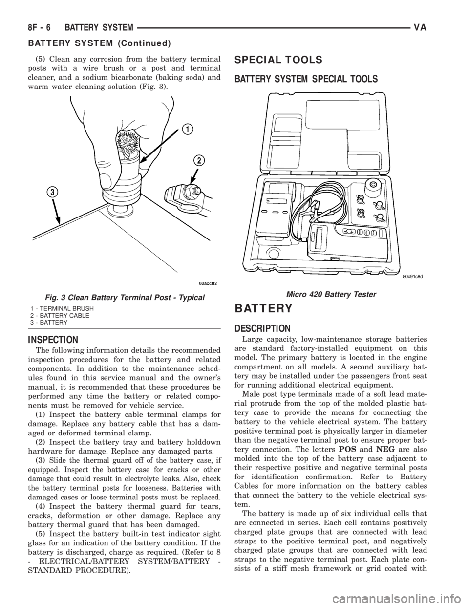
(5) Clean any corrosion from the battery terminal
posts with a wire brush or a post and terminal
cleaner, and a sodium bicarbonate (baking soda) and
warm water cleaning solution (Fig. 3).
INSPECTION
The following information details the recommended
inspection procedures for the battery and related
components. In addition to the maintenance sched-
ules found in this service manual and the owner's
manual, it is recommended that these procedures be
performed any time the battery or related compo-
nents must be removed for vehicle service.
(1) Inspect the battery cable terminal clamps for
damage. Replace any battery cable that has a dam-
aged or deformed terminal clamp.
(2) Inspect the battery tray and battery holddown
hardware for damage. Replace any damaged parts.
(3)
Slide the thermal guard off of the battery case, if
equipped. Inspect the battery case for cracks or other
damage that could result in electrolyte leaks. Also, check
the battery terminal posts for looseness. Batteries with
damaged cases or loose terminal posts must be replaced.
(4) Inspect the battery thermal guard for tears,
cracks, deformation or other damage. Replace any
battery thermal guard that has been damaged.
(5) Inspect the battery built-in test indicator sight
glass for an indication of the battery condition. If the
battery is discharged, charge as required. (Refer to 8
- ELECTRICAL/BATTERY SYSTEM/BATTERY -
STANDARD PROCEDURE).
SPECIAL TOOLS
BATTERY SYSTEM SPECIAL TOOLS
BATTERY
DESCRIPTION
Large capacity, low-maintenance storage batteries
are standard factory-installed equipment on this
model. The primary battery is located in the engine
compartment on all models. A second auxiliary bat-
tery may be installed under the passengers front seat
for running additional electrical equipment.
Male post type terminals made of a soft lead mate-
rial protrude from the top of the molded plastic bat-
tery case to provide the means for connecting the
battery to the vehicle electrical system. The battery
positive terminal post is physically larger in diameter
than the negative terminal post to ensure proper bat-
tery connection. The lettersPOSandNEGare also
molded into the top of the battery case adjacent to
their respective positive and negative terminal posts
for identification confirmation. Refer to Battery
Cables for more information on the battery cables
that connect the battery to the vehicle electrical sys-
tem.
The battery is made up of six individual cells that
are connected in series. Each cell contains positively
charged plate groups that are connected with lead
straps to the positive terminal post, and negatively
charged plate groups that are connected with lead
straps to the negative terminal post. Each plate con-
sists of a stiff mesh framework or grid coated with
Fig. 3 Clean Battery Terminal Post - Typical
1 - TERMINAL BRUSH
2 - BATTERY CABLE
3 - BATTERY
Micro 420 Battery Tester
8F - 6 BATTERY SYSTEMVA
BATTERY SYSTEM (Continued)
Page 141 of 1232
essary, use a battery terminal puller to remove the
terminal clamp from the battery post.
(6) Remove the battery hold downs from the bat-
tery (Refer to 8 - ELECTRICAL/BATTERY SYSTEM/
BATTERY HOLDDOWN - REMOVAL).
WARNING: WEAR A SUITABLE PAIR OF RUBBER
GLOVES (NOT THE HOUSEHOLD TYPE) WHEN
REMOVING A BATTERY BY HAND. SAFETY
GLASSES SHOULD ALSO BE WORN. IF THE BAT-
TERY IS CRACKED OR LEAKING, THE ELECTRO-
LYTE CAN BURN THE SKIN AND EYES.
(7) Remove the battery from the battery tray.
AUXILIARY BATTERY REMOVAL
(1) Turn the ignition switch to the Off position. Be
certain that all electrical accessories are turned off.
(2) Remove the passenger front seat assembly.
Refer to the Body section for procedure.
(3) Remove the top cover from the seat base
assembly.
(4) Loosen the battery negative cable terminal
clamp pinch-bolt hex nut.
(5) Disconnect the battery negative cable terminal
clamp from the battery negative terminal post. If
necessary, use a battery terminal puller to remove
the terminal clamp from the battery post.
(6) Loosen the battery positive cable terminal
clamp pinch-bolt hex nut.
(7) Disconnect the battery positive cable terminal
clamp from the battery positive terminal post. If nec-
essary, use a battery terminal puller to remove the
terminal clamp from the battery post.
(8) Remove the battery hold downs from the bat-
tery (Refer to 8 - ELECTRICAL/BATTERY SYSTEM/
BATTERY HOLDDOWN - REMOVAL).
WARNING: WEAR A SUITABLE PAIR OF RUBBER
GLOVES (NOT THE HOUSEHOLD TYPE) WHEN
REMOVING A BATTERY BY HAND. SAFETY
GLASSES SHOULD ALSO BE WORN. IF THE BAT-
TERY IS CRACKED OR LEAKING, THE ELECTRO-
LYTE CAN BURN THE SKIN AND EYES.
(9) Remove the battery from the battery tray.
INSTALLATION
UNDER HOOD BATTERY INSTALLATION
(1) Position the battery onto the battery tray.
Ensure that the battery positive and negative termi-
nal posts are correctly positioned. The battery cable
terminal clamps must reach the correct battery ter-
minal post without stretching the cables.(2) Reinstall the battery hold downs onto the bat-
tery (Refer to 8 - ELECTRICAL/BATTERY SYSTEM/
BATTERY HOLDDOWN - INSTALLATION).
CAUTION: Be certain that the battery cable terminal
clamps are connected to the correct battery termi-
nal posts. Reverse battery polarity may damage
electrical components of the vehicle.
(3) Reconnect the battery positive cable terminal
clamp to the battery positive terminal post. Tighten
the terminal clamp pinch-bolt hex nut to 11.8 N´m
(105 in. lbs.).
(4) Reconnect the battery negative cable terminal
clamp to the battery negative terminal post. Tighten
the terminal clamp pinch-bolt hex nut to 7.9 N´m (70
in. lbs.).
(5) Apply a thin coating of petroleum jelly or chas-
sis grease to the exposed surfaces of the battery cable
terminal clamps and the battery terminal posts.
AUXILIARY BATTERY INSTALLATION
(1) Position the battery onto the battery tray.
Ensure that the battery positive and negative termi-
nal posts are correctly positioned. The battery cable
terminal clamps must reach the correct battery ter-
minal post without stretching the cables.
(2) Reinstall the battery hold downs onto the bat-
tery (Refer to 8 - ELECTRICAL/BATTERY SYSTEM/
BATTERY HOLDDOWN - INSTALLATION).
CAUTION: Be certain that the battery cable terminal
clamps are connected to the correct battery termi-
nal posts. Reverse battery polarity may damage
electrical components of the vehicle.
(3) Reconnect the battery positive cable terminal
clamp to the battery positive terminal post. Tighten
the terminal clamp pinch-bolt hex nut to 11.8 N´m
(105 in. lbs.).
(4) Reconnect the battery negative cable terminal
clamp to the battery negative terminal post. Tighten
the terminal clamp pinch-bolt hex nut to 7.9 N´m (70
in. lbs.).
(5) Apply a thin coating of petroleum jelly or chas-
sis grease to the exposed surfaces of the battery cable
terminal clamps and the battery terminal posts.
(6) Install the top cover on the seat base assembly.
(7) Install the passenger front seat assembly. Refer
to the Body section for procedure.
VABATTERY SYSTEM 8F - 13
BATTERY (Continued)
Page 317 of 1232
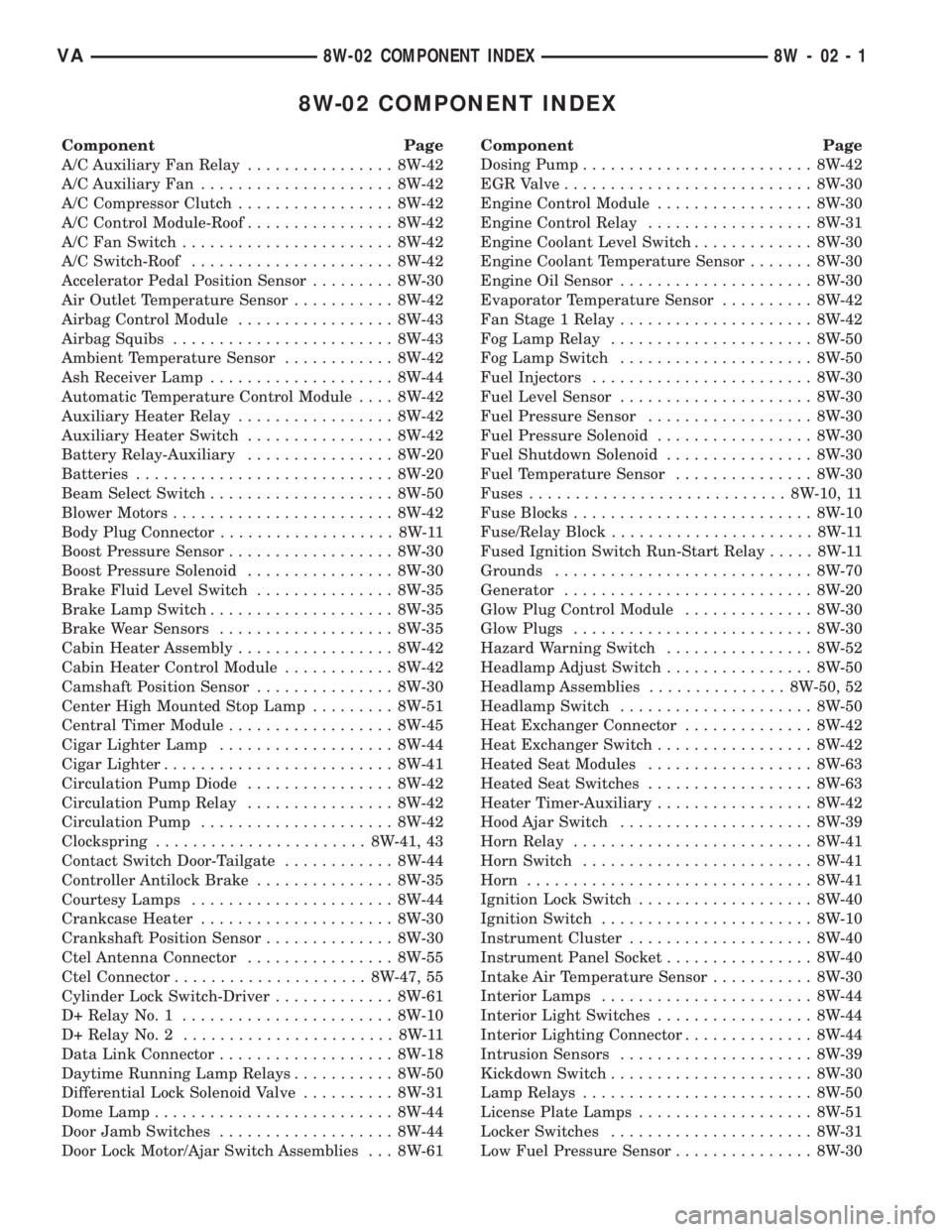
8W-02 COMPONENT INDEX
Component Page
A/C Auxiliary Fan Relay................ 8W-42
A/C Auxiliary Fan..................... 8W-42
A/C Compressor Clutch................. 8W-42
A/C Control Module-Roof................ 8W-42
A/C Fan Switch....................... 8W-42
A/C Switch-Roof...................... 8W-42
Accelerator Pedal Position Sensor......... 8W-30
Air Outlet Temperature Sensor........... 8W-42
Airbag Control Module................. 8W-43
Airbag Squibs........................ 8W-43
Ambient Temperature Sensor............ 8W-42
Ash Receiver Lamp.................... 8W-44
Automatic Temperature Control Module.... 8W-42
Auxiliary Heater Relay................. 8W-42
Auxiliary Heater Switch................ 8W-42
Battery Relay-Auxiliary................ 8W-20
Batteries............................ 8W-20
Beam Select Switch.................... 8W-50
Blower Motors........................ 8W-42
Body Plug Connector................... 8W-11
Boost Pressure Sensor.................. 8W-30
Boost Pressure Solenoid................ 8W-30
Brake Fluid Level Switch............... 8W-35
Brake Lamp Switch.................... 8W-35
Brake Wear Sensors................... 8W-35
Cabin Heater Assembly................. 8W-42
Cabin Heater Control Module............ 8W-42
Camshaft Position Sensor............... 8W-30
Center High Mounted Stop Lamp......... 8W-51
Central Timer Module.................. 8W-45
Cigar Lighter Lamp................... 8W-44
Cigar Lighter......................... 8W-41
Circulation Pump Diode................ 8W-42
Circulation Pump Relay................ 8W-42
Circulation Pump..................... 8W-42
Clockspring....................... 8W-41, 43
Contact Switch Door-Tailgate............ 8W-44
Controller Antilock Brake............... 8W-35
Courtesy Lamps...................... 8W-44
Crankcase Heater..................... 8W-30
Crankshaft Position Sensor.............. 8W-30
Ctel Antenna Connector................ 8W-55
Ctel Connector..................... 8W-47, 55
Cylinder Lock Switch-Driver............. 8W-61
D+ Relay No. 1....................... 8W-10
D+ Relay No. 2....................... 8W-11
Data Link Connector................... 8W-18
Daytime Running Lamp Relays........... 8W-50
Differential Lock Solenoid Valve.......... 8W-31
Dome Lamp.......................... 8W-44
Door Jamb Switches................... 8W-44
Door Lock Motor/Ajar Switch Assemblies . . . 8W-61Component Page
Dosing Pump......................... 8W-42
EGR Valve........................... 8W-30
Engine Control Module................. 8W-30
Engine Control Relay.................. 8W-31
Engine Coolant Level Switch............. 8W-30
Engine Coolant Temperature Sensor....... 8W-30
Engine Oil Sensor..................... 8W-30
Evaporator Temperature Sensor.......... 8W-42
Fan Stage 1 Relay..................... 8W-42
Fog Lamp Relay...................... 8W-50
Fog Lamp Switch..................... 8W-50
Fuel Injectors........................ 8W-30
Fuel Level Sensor..................... 8W-30
Fuel Pressure Sensor.................. 8W-30
Fuel Pressure Solenoid................. 8W-30
Fuel Shutdown Solenoid................ 8W-30
Fuel Temperature Sensor............... 8W-30
Fuses............................ 8W-10, 11
Fuse Blocks.......................... 8W-10
Fuse/Relay Block...................... 8W-11
Fused Ignition Switch Run-Start Relay..... 8W-11
Grounds............................ 8W-70
Generator........................... 8W-20
Glow Plug Control Module.............. 8W-30
Glow Plugs.......................... 8W-30
Hazard Warning Switch................ 8W-52
Headlamp Adjust Switch................ 8W-50
Headlamp Assemblies............... 8W-50, 52
Headlamp Switch..................... 8W-50
Heat Exchanger Connector.............. 8W-42
Heat Exchanger Switch................. 8W-42
Heated Seat Modules.................. 8W-63
Heated Seat Switches.................. 8W-63
Heater Timer-Auxiliary................. 8W-42
Hood Ajar Switch..................... 8W-39
Horn Relay.......................... 8W-41
Horn Switch......................... 8W-41
Horn............................... 8W-41
Ignition Lock Switch................... 8W-40
Ignition Switch....................... 8W-10
Instrument Cluster.................... 8W-40
Instrument Panel Socket................ 8W-40
Intake Air Temperature Sensor........... 8W-30
Interior Lamps....................... 8W-44
Interior Light Switches................. 8W-44
Interior Lighting Connector.............. 8W-44
Intrusion Sensors..................... 8W-39
Kickdown Switch...................... 8W-30
Lamp Relays......................... 8W-50
License Plate Lamps................... 8W-51
Locker Switches...................... 8W-31
Low Fuel Pressure Sensor............... 8W-30
VA8W-02 COMPONENT INDEX 8W - 02 - 1
Page 318 of 1232
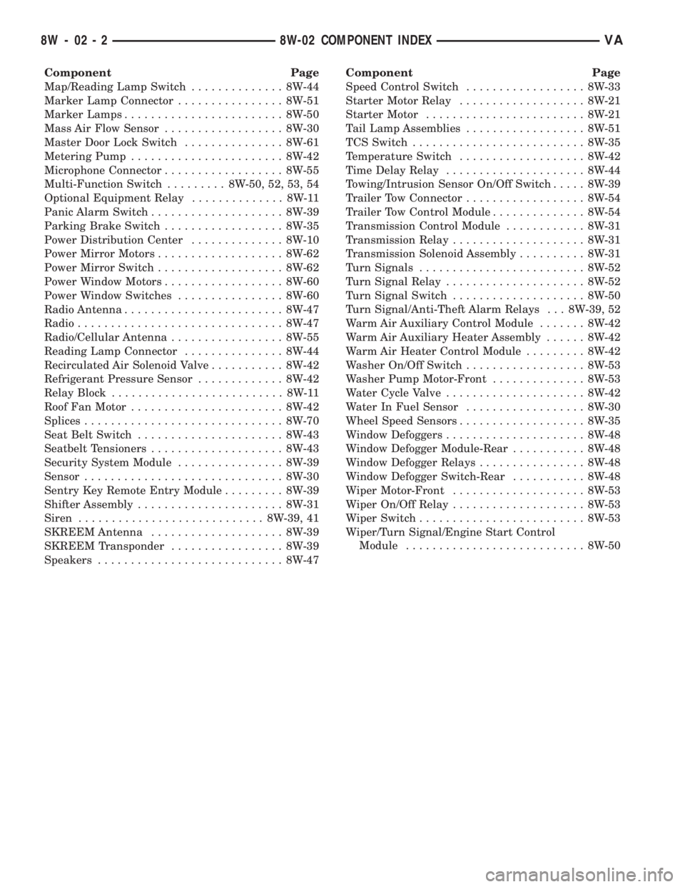
Component Page
Map/Reading Lamp Switch.............. 8W-44
Marker Lamp Connector................ 8W-51
Marker Lamps........................ 8W-50
Mass Air Flow Sensor.................. 8W-30
Master Door Lock Switch............... 8W-61
Metering Pump....................... 8W-42
Microphone Connector.................. 8W-55
Multi-Function Switch......... 8W-50, 52, 53, 54
Optional Equipment Relay.............. 8W-11
Panic Alarm Switch.................... 8W-39
Parking Brake Switch.................. 8W-35
Power Distribution Center.............. 8W-10
Power Mirror Motors................... 8W-62
Power Mirror Switch................... 8W-62
Power Window Motors.................. 8W-60
Power Window Switches................ 8W-60
Radio Antenna........................ 8W-47
Radio............................... 8W-47
Radio/Cellular Antenna................. 8W-55
Reading Lamp Connector............... 8W-44
Recirculated Air Solenoid Valve........... 8W-42
Refrigerant Pressure Sensor............. 8W-42
Relay Block.......................... 8W-11
Roof Fan Motor....................... 8W-42
Splices.............................. 8W-70
Seat Belt Switch...................... 8W-43
Seatbelt Tensioners.................... 8W-43
Security System Module................ 8W-39
Sensor.............................. 8W-30
Sentry Key Remote Entry Module......... 8W-39
Shifter Assembly...................... 8W-31
Siren............................ 8W-39, 41
SKREEM Antenna.................... 8W-39
SKREEM Transponder................. 8W-39
Speakers............................ 8W-47Component Page
Speed Control Switch.................. 8W-33
Starter Motor Relay................... 8W-21
Starter Motor........................ 8W-21
Tail Lamp Assemblies.................. 8W-51
TCS Switch.......................... 8W-35
Temperature Switch................... 8W-42
Time Delay Relay..................... 8W-44
Towing/Intrusion Sensor On/Off Switch..... 8W-39
Trailer Tow Connector.................. 8W-54
Trailer Tow Control Module.............. 8W-54
Transmission Control Module............ 8W-31
Transmission Relay.................... 8W-31
Transmission Solenoid Assembly.......... 8W-31
Turn Signals......................... 8W-52
Turn Signal Relay..................... 8W-52
Turn Signal Switch.................... 8W-50
Turn Signal/Anti-Theft Alarm Relays . . . 8W-39, 52
Warm Air Auxiliary Control Module....... 8W-42
Warm Air Auxiliary Heater Assembly...... 8W-42
Warm Air Heater Control Module......... 8W-42
Washer On/Off Switch.................. 8W-53
Washer Pump Motor-Front.............. 8W-53
Water Cycle Valve..................... 8W-42
Water In Fuel Sensor.................. 8W-30
Wheel Speed Sensors................... 8W-35
Window Defoggers..................... 8W-48
Window Defogger Module-Rear........... 8W-48
Window Defogger Relays................ 8W-48
Window Defogger Switch-Rear........... 8W-48
Wiper Motor-Front.................... 8W-53
Wiper On/Off Relay.................... 8W-53
Wiper Switch......................... 8W-53
Wiper/Turn Signal/Engine Start Control
Module........................... 8W-50
8W - 02 - 2 8W-02 COMPONENT INDEXVA
Page 319 of 1232
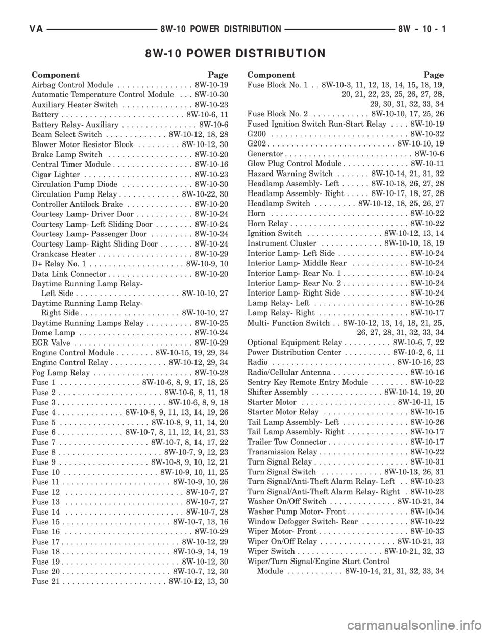
8W-10 POWER DISTRIBUTION
Component Page
Airbag Control Module................ 8W-10-19
Automatic Temperature Control Module . . . 8W-10-30
Auxiliary Heater Switch............... 8W-10-23
Battery.......................... 8W-10-6, 11
Battery Relay- Auxiliary................ 8W-10-6
Beam Select Switch............. 8W-10-12, 18, 28
Blower Motor Resistor Block......... 8W-10-12, 30
Brake Lamp Switch.................. 8W-10-20
Central Timer Module................. 8W-10-16
Cigar Lighter....................... 8W-10-23
Circulation Pump Diode............... 8W-10-30
Circulation Pump Relay............. 8W-10-22, 30
Controller Antilock Brake.............. 8W-10-20
Courtesy Lamp- Driver Door............ 8W-10-24
Courtesy Lamp- Left Sliding Door........ 8W-10-24
Courtesy Lamp- Passenger Door......... 8W-10-24
Courtesy Lamp- Right Sliding Door....... 8W-10-24
Crankcase Heater.................... 8W-10-29
D+ Relay No. 1.................... 8W-10-9, 10
Data Link Connector.................. 8W-10-20
Daytime Running Lamp Relay-
Left Side...................... 8W-10-10, 27
Daytime Running Lamp Relay-
Right Side..................... 8W-10-10, 27
Daytime Running Lamps Relay.......... 8W-10-25
Dome Lamp........................ 8W-10-24
EGR Valve......................... 8W-10-29
Engine Control Module........ 8W-10-15, 19, 29, 34
Engine Control Relay............ 8W-10-12, 29, 34
Fog Lamp Relay..................... 8W-10-28
Fuse 1................. 8W-10-6, 8, 9, 17, 18, 25
Fuse 2...................... 8W-10-6, 8, 11, 18
Fuse 3....................... 8W-10-6, 8, 9, 18
Fuse 4.............. 8W-10-8, 9, 11, 13, 14, 19, 26
Fuse 5................... 8W-10-8, 9, 11, 14, 20
Fuse 6.............. 8W-10-7, 8, 11, 12, 14, 21, 33
Fuse 7................... 8W-10-7, 8, 14, 17, 22
Fuse 8...................... 8W-10-7, 9, 12, 23
Fuse 9................... 8W-10-8, 9, 10, 12, 21
Fuse 10.................... 8W-10-9, 10, 11, 25
Fuse 11....................... 8W-10-9, 10, 26
Fuse 12......................... 8W-10-7, 27
Fuse 13......................... 8W-10-7, 27
Fuse 14......................... 8W-10-7, 28
Fuse 15....................... 8W-10-7, 13, 16
Fuse 16........................... 8W-10-29
Fuse 17......................... 8W-10-12, 29
Fuse 18....................... 8W-10-9, 14, 19
Fuse 19......................... 8W-10-12, 30
Fuse 20....................... 8W-10-7, 12, 30
Fuse 21...................... 8W-10-12, 13, 30
Component Page
Fuse Block No. 1 . . 8W-10-3, 11, 12, 13, 14, 15, 18, 19,
20, 21, 22, 23, 25, 26, 27, 28,
29, 30, 31, 32, 33, 34
Fuse Block No. 2............ 8W-10-10, 17, 25, 26
Fused Ignition Switch Run-Start Relay.... 8W-10-19
G200............................. 8W-10-32
G202........................... 8W-10-10, 19
Generator........................... 8W-10-6
Glow Plug Control Module.............. 8W-10-11
Hazard Warning Switch....... 8W-10-14, 21, 31, 32
Headlamp Assembly- Left...... 8W-10-18, 26, 27, 28
Headlamp Assembly- Right..... 8W-10-17, 18, 27, 28
Headlamp Switch......... 8W-10-12, 18, 25, 26, 27
Horn............................. 8W-10-22
Horn Relay......................... 8W-10-22
Ignition Switch................ 8W-10-12, 13, 14
Instrument Cluster............. 8W-10-10, 18, 19
Interior Lamp- Left Side............... 8W-10-24
Interior Lamp- Middle Rear............ 8W-10-24
Interior Lamp- Rear No. 1.............. 8W-10-24
Interior Lamp- Rear No. 2.............. 8W-10-24
Interior Lamp- Right Side.............. 8W-10-24
Lamp Relay- Left.................... 8W-10-26
Lamp Relay- Right................... 8W-10-17
Multi- Function Switch . . 8W-10-12, 13, 14, 18, 21, 25,
26, 27, 28, 31, 32, 33, 34
Optional Equipment Relay.......... 8W-10-6, 7, 22
Power Distribution Center.......... 8W-10-2, 6, 11
Radio.......................... 8W-10-16, 23
Radio/Cellular Antenna................ 8W-10-16
Sentry Key Remote Entry Module........ 8W-10-22
Shifter Assembly............... 8W-10-14, 19, 20
Starter Motor.................... 8W-10-11, 15
Starter Motor Relay.................. 8W-10-15
Tail Lamp Assembly- Left.............. 8W-10-26
Tail Lamp Assembly- Right............. 8W-10-17
Trailer Tow Connector................. 8W-10-17
Transmission Relay................... 8W-10-22
Turn Signal Relay.................... 8W-10-31
Turn Signal Switch............. 8W-10-13, 26, 31
Turn Signal/Anti-Theft Alarm Relay- Left . . 8W-10-23
Turn Signal/Anti-Theft Alarm Relay- Right . 8W-10-23
Washer On/Off Switch.............. 8W-10-21, 34
Washer Pump Motor- Front............. 8W-10-34
Window Defogger Switch- Rear.......... 8W-10-22
Wiper Motor- Front................... 8W-10-33
Wiper On/Off Relay................ 8W-10-21, 33
Wiper Switch.................. 8W-10-21, 32, 33
Wiper/Turn Signal/Engine Start Control
Module............ 8W-10-14, 21, 31, 32, 33, 34
VA8W-10 POWER DISTRIBUTION 8W - 10 - 1
Page 353 of 1232
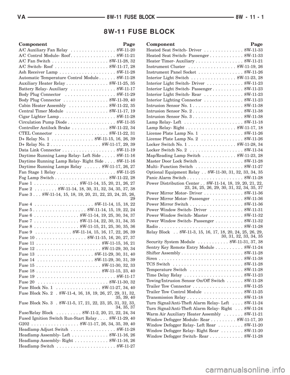
8W-11 FUSE BLOCK
Component Page
A/C Auxiliary Fan Relay................ 8W-11-20
A/C Control Module- Roof................ 8W-11-21
A/C Fan Switch.................... 8W-11-28, 32
A/C Switch- Roof................... 8W-11-17, 28
Ash Receiver Lamp.................... 8W-11-28
Automatic Temperature Control Module...... 8W-11-28
Auxiliary Heater Relay............... 8W-11-25, 35
Battery Relay- Auxiliary................ 8W-11-17
Body Plug Connector.................. 8W-11-29
Body Plug Connector................ 8W-11-39, 40
Cabin Heater Assembly.............. 8W-11-22, 35
Central Timer Module............... 8W-11-17, 19
Cigar Lighter Lamp.................... 8W-11-28
Circulation Pump Diode................. 8W-11-35
Controller Antilock Brake............. 8W-11-22, 34
CTEL Connector................... 8W-11-22, 31
D+ Relay No. 1............... 8W-11-15, 16, 26, 39
D+ Relay No. 2.................. 8W-11-17, 29, 39
Data Link Connector................... 8W-11-19
Daytime Running Lamp Relay- Left Side..... 8W-11-16
Daytime Running Lamp Relay- Right Side.... 8W-11-16
Daytime Running Lamps Relay...... 8W-11-17, 26, 27
Fan Stage 1 Relay..................... 8W-11-25
Fog Lamp Switch................... 8W-11-22, 28
Fuse 1................ 8W-11-14, 15, 20, 21, 26, 27
Fuse 2........ 8W-11-14, 18, 30, 31, 32, 34, 35, 37, 38
Fuse 3 . . . 8W-11-14, 15, 18, 19, 20, 21, 22, 23, 24, 25, 26,
29
Fuse 4..................... 8W-11-14, 15, 18, 22
Fuse 5................... 8W-11-14, 15, 19, 22, 24
Fuse 6................ 8W-11-14, 19, 25, 30, 34, 37
Fuse 7................ 8W-11-14, 22, 30, 31, 34, 35
Fuse 8................ 8W-11-15, 21, 25, 30, 35, 36
Fuse 9............. 8W-11-14, 15, 16, 17, 22, 26, 39
Fuse 10.................. 8W-11-15, 16, 20, 27, 37
Fuse 11....................... 8W-11-15, 16, 21
Fuse 12....................... 8W-11-29, 30, 34
Fuse 13.................... 8W-11-29, 30, 31, 40
Fuse 14.................... 8W-11-29, 30, 31, 39
Fuse 15....................... 8W-11-30, 32, 33
Fuse 18....................... 8W-11-15, 23, 40
Fuse 19............................ 8W-11-17
Fuse 20......................... 8W-11-30, 32
Fuse Block No. 1................ 8W-11-27, 34, 40
Fuse Block No. 2 . 8W-11-4, 16, 18, 19, 26, 27, 29, 31, 32,
35, 39, 40
Fuse Block No. 3 . 8W-11-5, 17, 21, 22, 23, 25, 31, 32, 33,
34, 35, 37
Fuse/Relay Block......... 8W-11-2, 20, 21, 22, 24, 34
Fused Ignition Switch Run-Start Relay.... 8W-11-29, 40
G202................. 8W-11-17, 26, 34, 35, 39, 40
Headlamp Adjust Switch................ 8W-11-28
Headlamp Assembly- Left............. 8W-11-16, 26
Headlamp Assembly- Right............ 8W-11-16, 26
Headlamp Switch..................... 8W-11-27
Component Page
Heated Seat Switch- Driver.............. 8W-11-33
Heated Seat Switch- Passenger............ 8W-11-33
Heater Timer- Auxiliary................. 8W-11-21
Instrument Cluster................. 8W-11-19, 26
Instrument Panel Socket................ 8W-11-26
Interior Light Switch................ 8W-11-23, 28
Interior Light Switch- Driver............. 8W-11-23
Interior Light Switch- Passenger........... 8W-11-23
Interior Light Switch- Rear.............. 8W-11-23
Interior Lighting Connector.............. 8W-11-23
Intrusion Sensor No. 1.................. 8W-11-38
Intrusion Sensor No. 2.................. 8W-11-38
Intrusion Sensor No. 3.................. 8W-11-38
Lamp Relay- Left..................... 8W-11-18
Lamp Relay- Right.................. 8W-11-17, 18
License Plate Lamp No. 1............... 8W-11-26
License Plate Lamp No. 2............... 8W-11-26
Locker Switch No. 1................. 8W-11-28, 34
Locker Switch No. 2................... 8W-11-34
Map/Reading Lamp Switch............ 8W-11-23, 28
Master Door Lock Switch................ 8W-11-28
Multi- Function Switch................. 8W-11-27
Optional Equipment Relay . . 8W-11-30, 31, 32, 33, 34, 35
Panic Alarm Switch.................... 8W-11-28
Power Distribution Center . . 8W-11-14, 18, 19, 20, 21, 22,
23, 24, 25, 26, 29, 30, 31, 32, 34, 35, 37
Power Mirror Motor- Driver.............. 8W-11-36
Power Mirror Motor- Passenger........... 8W-11-36
Power Mirror Switch................... 8W-11-36
Power Window Switch- Driver............ 8W-11-31
Power Window Switch- Master............ 8W-11-32
Power Window Switch- Passenger.......... 8W-11-32
Radio.............................. 8W-11-28
Relay Block . . 8W-11-3, 15, 16, 17, 18, 20, 24, 25, 26, 29,
30, 31, 32, 33, 34, 35
Security System Module........... 8W-11-31, 37, 38
Sentry Key Remote Entry Module.......... 8W-11-24
Shifter Assembly...................... 8W-11-28
Siren.............................. 8W-11-38
TCS Switch......................... 8W-11-28
Temperature Switch................... 8W-11-28
Time Delay Relay..................... 8W-11-23
Towing/Intrusion Sensor On/Off Switch...... 8W-11-28
Trailer Tow Connector.................. 8W-11-25
Trailer Tow Control Module.............. 8W-11-25
Transmission Relay.................... 8W-11-18
Turn Signal/Anti-Theft Alarm Relay- Left.... 8W-11-24
Turn Signal/Anti-Theft Alarm Relay- Right . . . 8W-11-24
Warm Air Auxiliary Heater Assembly....... 8W-11-21
Window Defogger Module- Rear......... 8W-11-17, 20
Window Defogger Relay- Left Rear......... 8W-11-20
Window Defogger Relay- Right Rear........ 8W-11-20
Window Defogger Switch- Rear............ 8W-11-28
VA8W-11 FUSE BLOCK 8W - 11 - 1