2005 MERCEDES-BENZ SPRINTER wheel bolts
[x] Cancel search: wheel boltsPage 90 of 1232
LEVER
REMOVAL
(1) Disconnect the front brake cable from the pul-
ley unit.
(2) Remove the front brake cable from the hand
brake lever (Fig. 29).
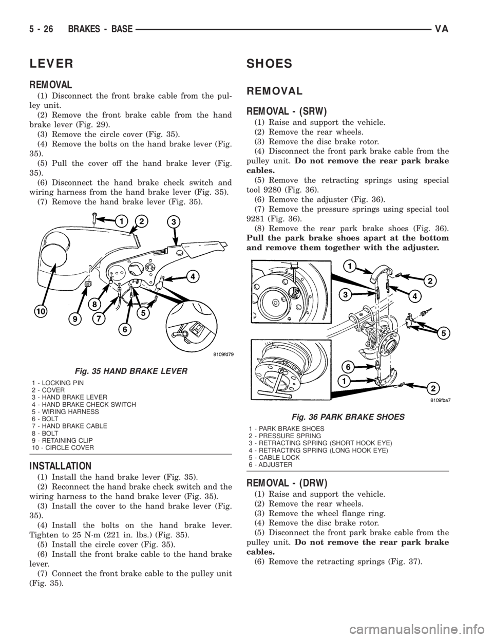
(3) Remove the circle cover (Fig. 35).
(4) Remove the bolts on the hand brake lever (Fig.
35).
(5) Pull the cover off the hand brake lever (Fig.
35).
(6) Disconnect the hand brake check switch and
wiring harness from the hand brake lever (Fig. 35).
(7) Remove the hand brake lever (Fig. 35).
INSTALLATION
(1) Install the hand brake lever (Fig. 35).
(2) Reconnect the hand brake check switch and the
wiring harness to the hand brake lever (Fig. 35).
(3) Install the cover to the hand brake lever (Fig.
35).
(4) Install the bolts on the hand brake lever.
Tighten to 25 N´m (221 in. lbs.) (Fig. 35).
(5) Install the circle cover (Fig. 35).
(6) Install the front brake cable to the hand brake
lever.
(7) Connect the front brake cable to the pulley unit
(Fig. 35).
SHOES
REMOVAL
REMOVAL - (SRW)
(1) Raise and support the vehicle.
(2) Remove the rear wheels.
(3) Remove the disc brake rotor.
(4) Disconnect the front park brake cable from the
pulley unit.Do not remove the rear park brake
cables.
(5) Remove the retracting springs using special
tool 9280 (Fig. 36).
(6) Remove the adjuster (Fig. 36).
(7) Remove the pressure springs using special tool
9281 (Fig. 36).
(8) Remove the rear park brake shoes (Fig. 36).
Pull the park brake shoes apart at the bottom
and remove them together with the adjuster.
REMOVAL - (DRW)
(1) Raise and support the vehicle.
(2) Remove the rear wheels.
(3) Remove the wheel flange ring.
(4) Remove the disc brake rotor.
(5) Disconnect the front park brake cable from the
pulley unit.Do not remove the rear park brake
cables.
(6) Remove the retracting springs (Fig. 37).
Fig. 35 HAND BRAKE LEVER
1 - LOCKING PIN
2 - COVER
3 - HAND BRAKE LEVER
4 - HAND BRAKE CHECK SWITCH
5 - WIRING HARNESS
6 - BOLT
7 - HAND BRAKE CABLE
8 - BOLT
9 - RETAINING CLIP
10 - CIRCLE COVER
Fig. 36 PARK BRAKE SHOES
1 - PARK BRAKE SHOES
2 - PRESSURE SPRING
3 - RETRACTING SPRING (SHORT HOOK EYE)
4 - RETRACTING SPRING (LONG HOOK EYE)
5 - CABLE LOCK
6 - ADJUSTER
5 - 26 BRAKES - BASEVA
Page 144 of 1232
REMOVAL
(1) Turn the ignition switch to the Off position. Be
certain that all electrical accessories are turned off.
(2) Disconnect and isolate the remote battery neg-
ative cable terminal.
(3) One at a time, trace and disconnect the battery
cable retaining pushpins, fasteners and routing clips
until the cables are free from the vehicle.
(4)
Feed the battery cable assembly out of the vehicle.
INSTALLATION
(1) Position the battery cable in the vehicle.
(2) One at a time, install the battery cable retain-
ing pushpins, fasteners and routing clips until the
cable is installed exactly in the factory installed loca-
tion in the vehicle. Refer to the Wiring Diagram sec-
tion of the service manual for reference.
(3) Connect the battery negative cable terminal.
BATTERY TRAY
DESCRIPTION
The battery is mounted in a stamped steel battery
tray located in the left front corner of the engine
compartment. The battery tray is secured with bolts
to the left front wheelhouse inner steel panel. A hole
in the bottom of the battery tray is fitted with a
formed drain tube. A second hole in the bottom of the
tray is fitted with a battery temperature sensor.
OPERATION
The battery tray provides a mounting location and
support for the vehicle battery. The battery tray sup-
port supports the battery tray and provides an
anchor point for the inboard battery hold down hard-
ware. The battery tray and the battery hold down
hardware combine to secure and stabilize the battery
in the engine compartment, which prevents battery
movement during vehicle operation. Unrestrained
battery movement during vehicle operation could
result in damage to the vehicle, the battery or both.
The battery tray drain tube directs spilled water or
electrolyte from a leaking battery to the ground
through another hole in the front extension of the
left front wheelhouse inner panel.
REMOVAL
(1) Remove the battery from the battery tray.
(Refer to 8 - ELECTRICAL/BATTERY SYSTEM/BAT-
TERY - REMOVAL).
(2) Remove the battery temperature sensor from
the battery tray. (Refer to 8 - ELECTRICAL/CHARG-
ING/BATTERY TEMPERATURE SENSOR -
REMOVAL).
(3) Remove the bolts that secure the battery tray
to the battery tray support.
(4) Remove the battery tray from the vehicle.
INSTALLATION
(1) Clean and inspect the battery tray.(Refer to 8 -
ELECTRICAL/BATTERY SYSTEM - CLEANING).
(2) Position the battery tray onto the battery tray
support.
(3) Install and tighten the bolts that secure the
battery tray to the battery tray support. Tighten the
screws to 11.8 N´m (105 in. lbs.).
(4) Install the battery temperature sensor onto the
battery tray. (Refer to 8 - ELECTRICAL/CHARGING/
BATTERY TEMPERATURE SENSOR - INSTALLA-
TION).
(5) Install the battery onto the battery tray. (Refer
to 8 - ELECTRICAL/BATTERY SYSTEM/BATTERY -
INSTALLATION).
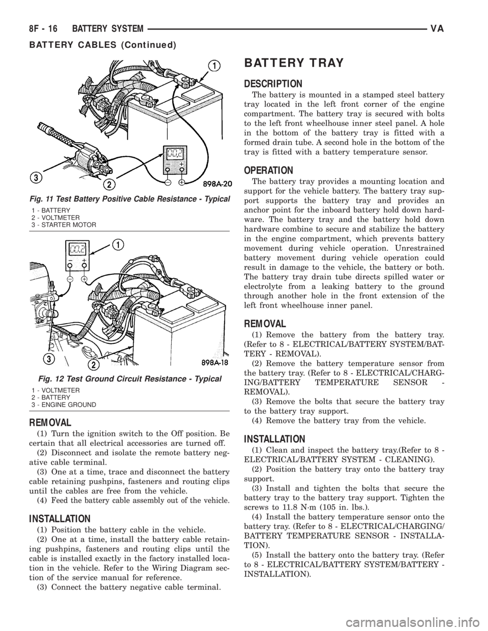
Fig. 11 Test Battery Positive Cable Resistance - Typical
1 - BATTERY
2 - VOLTMETER
3 - STARTER MOTOR
Fig. 12 Test Ground Circuit Resistance - Typical
1 - VOLTMETER
2 - BATTERY
3 - ENGINE GROUND
8F - 16 BATTERY SYSTEMVA
BATTERY CABLES (Continued)
Page 243 of 1232
WARNING
WARNINGS - RESTRAINT SYSTEM
WARNING: DURING AND FOLLOWING ANY SEAT
BELT SERVICE, CAREFULLY INSPECT ALL SEAT
BELTS, BUCKLES, MOUNTING HARDWARE,
RETRACTORS, TETHER STRAPS, AND ANCHORS
FOR PROPER INSTALLATION, OPERATION, OR
DAMAGE. REPLACE ANY BELT THAT IS CUT,
FRAYED, OR TORN. STRAIGHTEN ANY BELT THAT
IS TWISTED. TIGHTEN ANY LOOSE FASTENERS.
REPLACE ANY BELT THAT HAS A DAMAGED OR
INOPERATIVE BUCKLE OR RETRACTOR. REPLACE
ANY BELT THAT HAS A BENT OR DAMAGED
LATCH PLATE OR ANCHOR PLATE. NEVER
ATTEMPT TO REPAIR A SEAT BELT COMPONENT.
ALWAYS REPLACE DAMAGED OR FAULTY SEAT
BELT COMPONENTS WITH THE CORRECT, NEW
AND UNUSED REPLACEMENT PARTS LISTED IN
THE DAIMLERCHRYSLER MOPAR PARTS CATA-
LOG.
WARNING: ON VEHICLES EQUIPPED WITH AIR-
BAGS, DISABLE THE SUPPLEMENTAL RESTRAINT
SYSTEM BEFORE ATTEMPTING ANY STEERING
WHEEL, STEERING COLUMN, DRIVER AIRBAG,
PASSENGER AIRBAG, SEAT BELT TENSIONER, OR
INSTRUMENT PANEL COMPONENT DIAGNOSIS OR
SERVICE. DISCONNECT AND ISOLATE THE BAT-
TERY NEGATIVE (GROUND) CABLE, THEN WAIT
TWO MINUTES FOR THE SYSTEM CAPACITOR TO
DISCHARGE BEFORE PERFORMING FURTHER
DIAGNOSIS OR SERVICE. THIS IS THE ONLY SURE
WAY TO DISABLE THE SUPPLEMENTAL
RESTRAINT SYSTEM. FAILURE TO TAKE THE
PROPER PRECAUTIONS COULD RESULT IN ACCI-
DENTAL AIRBAG DEPLOYMENT AND POSSIBLE
PERSONAL INJURY.
WARNING: ON VEHICLES EQUIPPED WITH AIR-
BAGS, BEFORE PERFORMING ANY WELDING
OPERATIONS DISCONNECT AND ISOLATE THE
BATTERY NEGATIVE (GROUND) CABLE AND DIS-
CONNECT ALL WIRE HARNESS CONNECTORS
FROM THE AIRBAG CONTROL MODULE (ACM).
FAILURE TO TAKE THE PROPER PRECAUTIONS
COULD RESULT IN ACCIDENTAL AIRBAG DEPLOY-
MENT AND OTHER POSSIBLE DAMAGE TO THE
SUPPLEMENTAL RESTRAINT SYSTEM CIRCUITS
AND COMPONENTS.
WARNING: AN AIRBAG INFLATOR UNIT MAY CON-
TAIN SODIUM AZIDE AND POTASSIUM NITRATE.THESE MATERIALS ARE POISONOUS AND
EXTREMELY FLAMMABLE. CONTACT WITH ACID,
WATER, OR HEAVY METALS MAY PRODUCE HARM-
FUL AND IRRITATING GASES (SODIUM HYDROXIDE
IS FORMED IN THE PRESENCE OF MOISTURE) OR
COMBUSTIBLE COMPOUNDS. AN AIRBAG INFLA-
TOR UNIT MAY ALSO CONTAIN A GAS CANISTER
PRESSURIZED TO OVER 2500 PSI. DO NOT
ATTEMPT TO DISMANTLE AN AIRBAG UNIT OR
TAMPER WITH ITS INFLATOR. DO NOT PUNCTURE,
INCINERATE, OR BRING INTO CONTACT WITH
ELECTRICITY. DO NOT STORE AT TEMPERATURES
EXCEEDING 93É C (200É F).
WARNING: WHEN HANDLING A SEAT BELT TEN-
SIONER RETRACTOR, PROPER CARE SHOULD BE
EXERCISED TO KEEP FINGERS OUT FROM UNDER
THE RETRACTOR COVER AND AWAY FROM THE
SEAT BELT WEBBING WHERE IT EXITS FROM THE
RETRACTOR COVER.
WARNING: REPLACE ALL RESTRAINT SYSTEM
COMPONENTS ONLY WITH PARTS SPECIFIED IN
THE DAIMLERCHRYSLER MOPAR PARTS CATA-
LOG. SUBSTITUTE PARTS MAY APPEAR INTER-
CHANGEABLE, BUT INTERNAL DIFFERENCES MAY
RESULT IN INFERIOR OCCUPANT PROTECTION.
WARNING: THE FASTENERS, SCREWS, AND
BOLTS ORIGINALLY USED FOR THE RESTRAINT
SYSTEM COMPONENTS HAVE SPECIAL COATINGS
AND ARE SPECIFICALLY DESIGNED FOR THE
RESTRAINT SYSTEM. THEY MUST NEVER BE
REPLACED WITH ANY SUBSTITUTES. ANY TIME A
NEW FASTENER IS NEEDED, REPLACE IT WITH
THE CORRECT FASTENERS PROVIDED IN THE
SERVICE PACKAGE OR SPECIFIED IN THE
DAIMLERCHRYSLER MOPAR PARTS CATALOG.
WARNING: WHEN A STEERING COLUMN HAS AN
AIRBAG UNIT ATTACHED, NEVER PLACE THE COL-
UMN ON THE FLOOR OR ANY OTHER SURFACE
WITH THE STEERING WHEEL OR AIRBAG UNIT
FACE DOWN.
DIAGNOSIS AND TESTING - SUPPLEMENTAL
RESTRAINT SYSTEM
Proper diagnosis and testing of the supplemental
restraint system components or the Airbag Control
Module (ACM), initialization of the ACM, as well as
the retrieval or erasure of a Diagnostic Trouble Code
(DTC) from the ACM requires the use of a DRBIIIt
scan tool. Refer to the appropriate diagnostic infor-
mation.
VARESTRAINTS 8O - 5
RESTRAINTS (Continued)
Page 775 of 1232
CRANKSHAFT OIL SEAL -
REAR
REMOVAL
This must be done with the transmission removed
from the vehicle.
(1) Disconnect the negative battery cable.
(2) Raise and support the vehicle.
(3) Drain the engine oil.
NOTE: Loosen all of the oil pan bolts to assure that
the oil pan gasket is not damaged when removing
the rear main oil seal and end cover assembly.
NOTE: Inspect the oil pan gasket for damage. If the
oil pan gasket is damaged, remove the oil pan and
replace the oil pan gasket.
(4) Loosen the oil pan bolts.
(5) Remove the flywheel.CAUTION: Care must be taken when removing the
rear main seal and adaptor assembly. Failure to do
so will result in damage to the oil pan gasket.
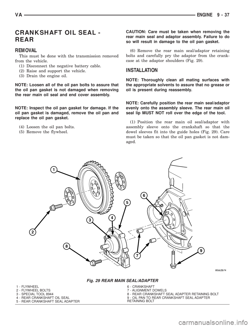
(6) Remove the rear main seal/adaptor retaining
bolts and carefully pry the adaptor from the crank-
case at the adaptor shoulders (Fig. 29).
INSTALLATION
NOTE: Thoroughly clean all mating surfaces with
the appropriate solvents to assure that no grease or
oil is present during reassembly.
NOTE: Carefully position the rear main seal/adaptor
evenly onto the assembly sleeve. The rear main oil
seal lip MUST NOT roll over the edge of the tool.
(1) Position the rear main oil seal/adaptor with
assembly sleeve onto the crankshaft so that the
dowel sleeves fit into the guide holes (Fig. 29). Care
must be taken so that the oil pan gasket is not dam-
aged.
Fig. 29 REAR MAIN SEAL/ADAPTER
1 - FLYWHEEL
2 - FLYWHEEL BOLTS
3 - SPECIAL TOOL 8944
4 - REAR CRANKSHAFT OIL SEAL
5 - REAR CRANKSHAFT SEAL ADAPTER6 - CRANKSHAFT
7 - ALIGNMENT DOWELS
8 - REAR CRANKSHAFT SEAL ADAPTER RETAINING BOLT
9 - OIL PAN TO REAR CRANKSHAFT SEAL ADAPTER
RETAINING BOLT
VAENGINE 9 - 37
Page 776 of 1232
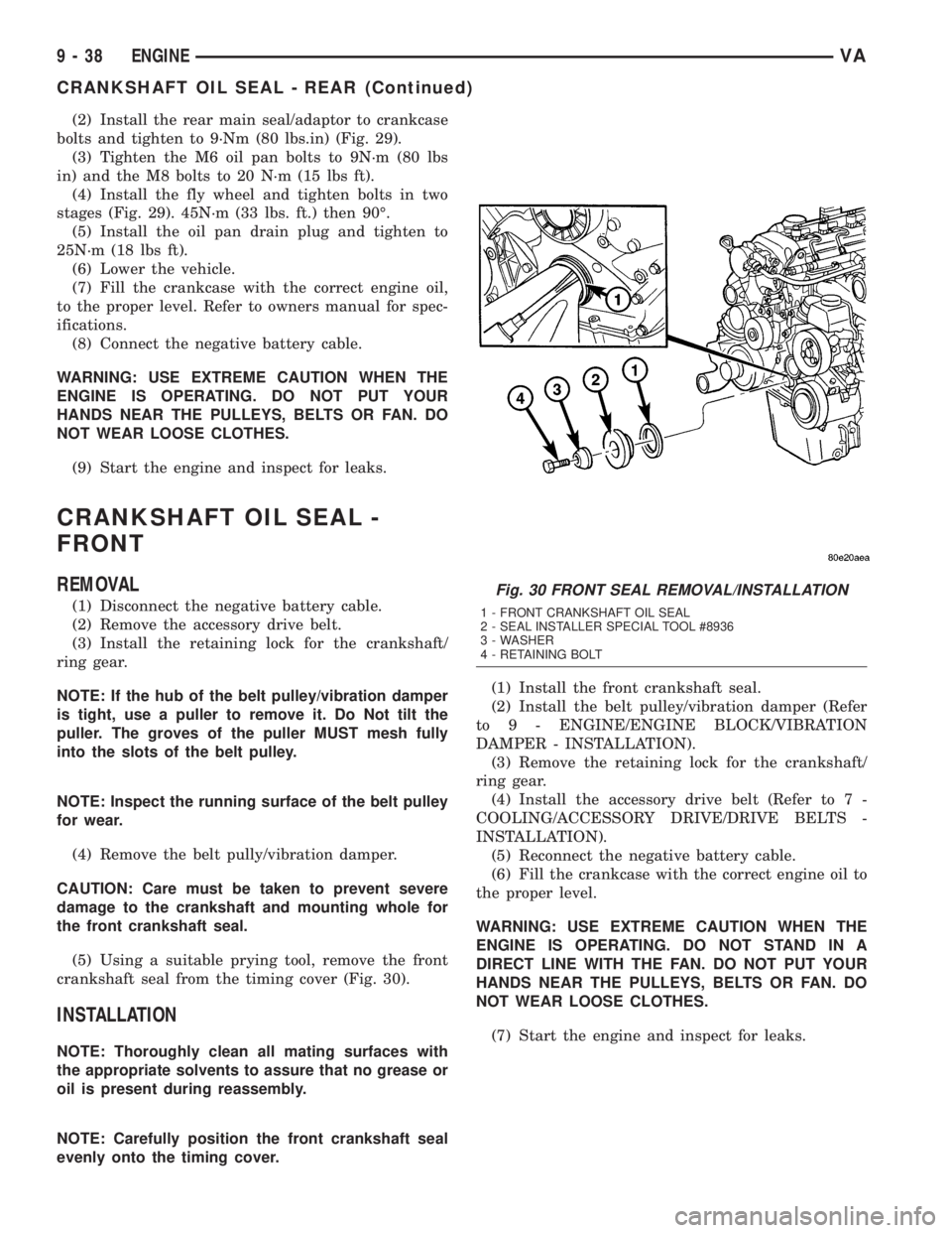
(2) Install the rear main seal/adaptor to crankcase
bolts and tighten to 9´Nm (80 lbs.in) (Fig. 29).
(3) Tighten the M6 oil pan bolts to 9N´m (80 lbs
in) and the M8 bolts to 20 N´m (15 lbs ft).
(4) Install the fly wheel and tighten bolts in two
stages (Fig. 29). 45N´m (33 lbs. ft.) then 90É.
(5) Install the oil pan drain plug and tighten to
25N´m (18 lbs ft).
(6) Lower the vehicle.
(7) Fill the crankcase with the correct engine oil,
to the proper level. Refer to owners manual for spec-
ifications.
(8) Connect the negative battery cable.
WARNING: USE EXTREME CAUTION WHEN THE
ENGINE IS OPERATING. DO NOT PUT YOUR
HANDS NEAR THE PULLEYS, BELTS OR FAN. DO
NOT WEAR LOOSE CLOTHES.
(9) Start the engine and inspect for leaks.
CRANKSHAFT OIL SEAL -
FRONT
REMOVAL
(1) Disconnect the negative battery cable.
(2) Remove the accessory drive belt.
(3) Install the retaining lock for the crankshaft/
ring gear.
NOTE: If the hub of the belt pulley/vibration damper
is tight, use a puller to remove it. Do Not tilt the
puller. The groves of the puller MUST mesh fully
into the slots of the belt pulley.
NOTE: Inspect the running surface of the belt pulley
for wear.
(4) Remove the belt pully/vibration damper.
CAUTION: Care must be taken to prevent severe
damage to the crankshaft and mounting whole for
the front crankshaft seal.
(5) Using a suitable prying tool, remove the front
crankshaft seal from the timing cover (Fig. 30).
INSTALLATION
NOTE: Thoroughly clean all mating surfaces with
the appropriate solvents to assure that no grease or
oil is present during reassembly.
NOTE: Carefully position the front crankshaft seal
evenly onto the timing cover.(1) Install the front crankshaft seal.
(2) Install the belt pulley/vibration damper (Refer
to 9 - ENGINE/ENGINE BLOCK/VIBRATION
DAMPER - INSTALLATION).
(3) Remove the retaining lock for the crankshaft/
ring gear.
(4) Install the accessory drive belt (Refer to 7 -
COOLING/ACCESSORY DRIVE/DRIVE BELTS -
INSTALLATION).
(5) Reconnect the negative battery cable.
(6) Fill the crankcase with the correct engine oil to
the proper level.
WARNING: USE EXTREME CAUTION WHEN THE
ENGINE IS OPERATING. DO NOT STAND IN A
DIRECT LINE WITH THE FAN. DO NOT PUT YOUR
HANDS NEAR THE PULLEYS, BELTS OR FAN. DO
NOT WEAR LOOSE CLOTHES.
(7) Start the engine and inspect for leaks.
Fig. 30 FRONT SEAL REMOVAL/INSTALLATION
1 - FRONT CRANKSHAFT OIL SEAL
2 - SEAL INSTALLER SPECIAL TOOL #8936
3 - WASHER
4 - RETAINING BOLT
9 - 38 ENGINEVA
CRANKSHAFT OIL SEAL - REAR (Continued)
Page 777 of 1232
FLYWHEEL
REMOVAL
(1) Remove transmission (Refer to 21 - TRANS-
MISSION/TRANSAXLE/AUTOMATIC - W5J400 -
REMOVAL).
NOTE: M6x90 bolts must be used with retaining
lock to prevent damage to rear end cover.
(2) Install retaining lock for crankshaft/starter
ring gear.
NOTE: Flywheel does not need balancing or should
it be interchanged.
(3) Remove flywheel with both inner and outer
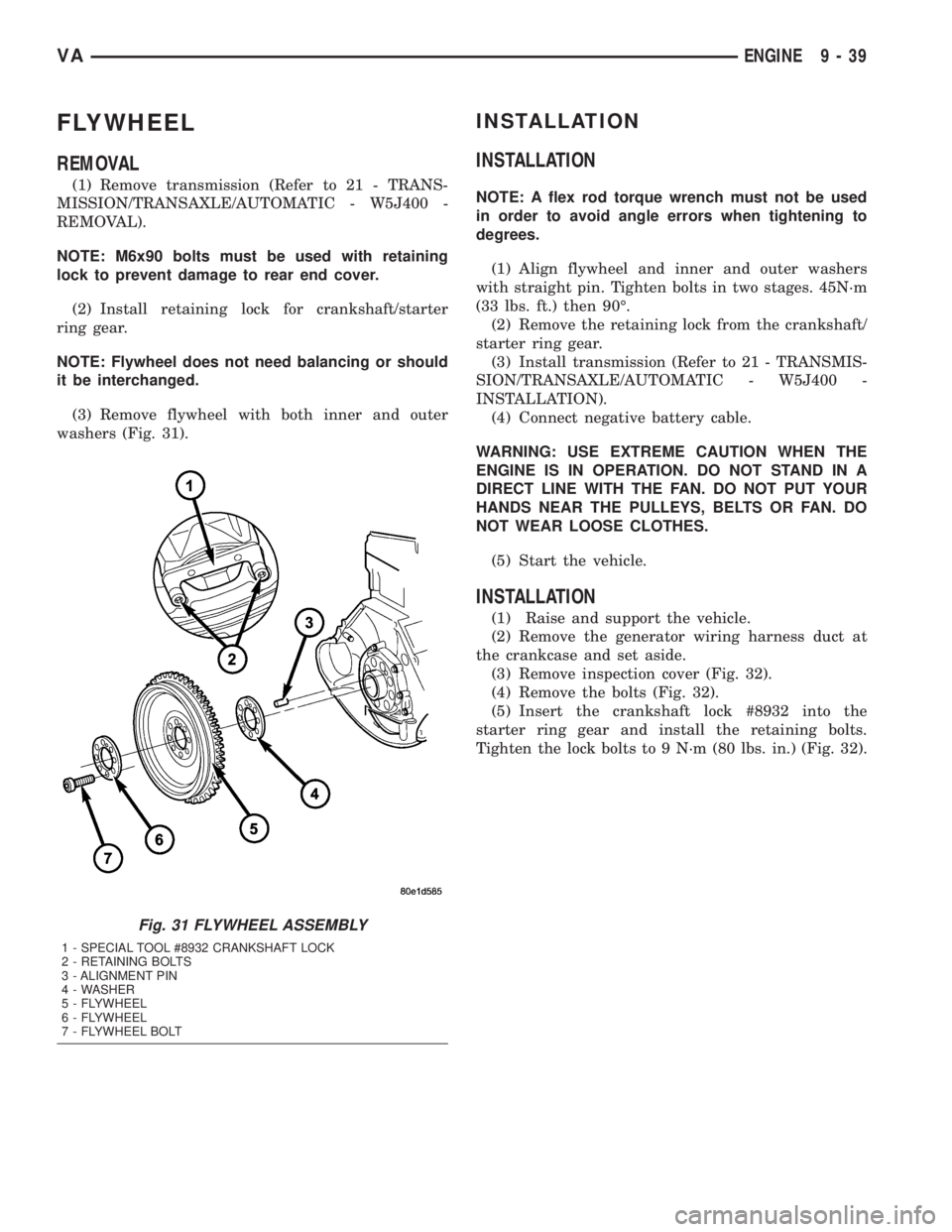
washers (Fig. 31).
INSTALLATION
INSTALLATION
NOTE: A flex rod torque wrench must not be used
in order to avoid angle errors when tightening to
degrees.
(1) Align flywheel and inner and outer washers
with straight pin. Tighten bolts in two stages. 45N´m
(33 lbs. ft.) then 90É.
(2) Remove the retaining lock from the crankshaft/
starter ring gear.
(3) Install transmission (Refer to 21 - TRANSMIS-
SION/TRANSAXLE/AUTOMATIC - W5J400 -
INSTALLATION).
(4) Connect negative battery cable.
WARNING: USE EXTREME CAUTION WHEN THE
ENGINE IS IN OPERATION. DO NOT STAND IN A
DIRECT LINE WITH THE FAN. DO NOT PUT YOUR
HANDS NEAR THE PULLEYS, BELTS OR FAN. DO
NOT WEAR LOOSE CLOTHES.
(5) Start the vehicle.
INSTALLATION
(1) Raise and support the vehicle.
(2) Remove the generator wiring harness duct at
the crankcase and set aside.
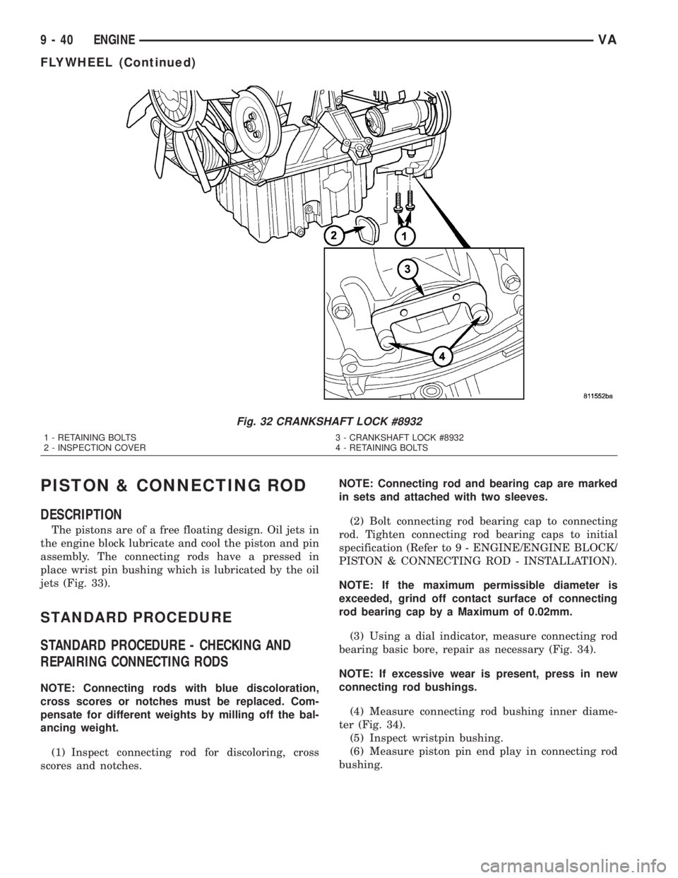
(3) Remove inspection cover (Fig. 32).
(4) Remove the bolts (Fig. 32).
(5) Insert the crankshaft lock #8932 into the
starter ring gear and install the retaining bolts.
Tighten the lock bolts to 9 N´m (80 lbs. in.) (Fig. 32).
Fig. 31 FLYWHEEL ASSEMBLY
1 - SPECIAL TOOL #8932 CRANKSHAFT LOCK
2 - RETAINING BOLTS
3 - ALIGNMENT PIN
4 - WASHER
5 - FLYWHEEL
6 - FLYWHEEL
7 - FLYWHEEL BOLT
VAENGINE 9 - 39
Page 778 of 1232
PISTON & CONNECTING ROD
DESCRIPTION
The pistons are of a free floating design. Oil jets in
the engine block lubricate and cool the piston and pin
assembly. The connecting rods have a pressed in
place wrist pin bushing which is lubricated by the oil
jets (Fig. 33).
STANDARD PROCEDURE
STANDARD PROCEDURE - CHECKING AND
REPAIRING CONNECTING RODS
NOTE: Connecting rods with blue discoloration,
cross scores or notches must be replaced. Com-
pensate for different weights by milling off the bal-
ancing weight.
(1) Inspect connecting rod for discoloring, cross
scores and notches.NOTE: Connecting rod and bearing cap are marked
in sets and attached with two sleeves.
(2) Bolt connecting rod bearing cap to connecting
rod. Tighten connecting rod bearing caps to initial
specification (Refer to 9 - ENGINE/ENGINE BLOCK/
PISTON & CONNECTING ROD - INSTALLATION).
NOTE: If the maximum permissible diameter is
exceeded, grind off contact surface of connecting
rod bearing cap by a Maximum of 0.02mm.
(3) Using a dial indicator, measure connecting rod
bearing basic bore, repair as necessary (Fig. 34).
NOTE: If excessive wear is present, press in new
connecting rod bushings.
(4) Measure connecting rod bushing inner diame-
ter (Fig. 34).
(5) Inspect wristpin bushing.
(6) Measure piston pin end play in connecting rod
bushing.
Fig. 32 CRANKSHAFT LOCK #8932
1 - RETAINING BOLTS 3 - CRANKSHAFT LOCK #8932
2 - INSPECTION COVER 4 - RETAINING BOLTS
9 - 40 ENGINEVA
FLYWHEEL (Continued)
Page 825 of 1232
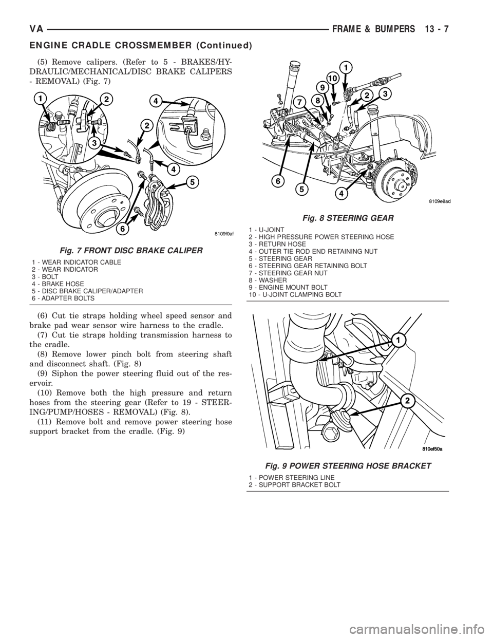
(5) Remove calipers. (Refer to 5 - BRAKES/HY-
DRAULIC/MECHANICAL/DISC BRAKE CALIPERS
- REMOVAL) (Fig. 7)
(6) Cut tie straps holding wheel speed sensor and
brake pad wear sensor wire harness to the cradle.
(7) Cut tie straps holding transmission harness to
the cradle.
(8) Remove lower pinch bolt from steering shaft
and disconnect shaft. (Fig. 8)
(9) Siphon the power steering fluid out of the res-
ervoir.
(10) Remove both the high pressure and return
hoses from the steering gear (Refer to 19 - STEER-
ING/PUMP/HOSES - REMOVAL) (Fig. 8).
(11) Remove bolt and remove power steering hose
support bracket from the cradle. (Fig. 9)
Fig. 7 FRONT DISC BRAKE CALIPER
1 - WEAR INDICATOR CABLE
2 - WEAR INDICATOR
3 - BOLT
4 - BRAKE HOSE
5 - DISC BRAKE CALIPER/ADAPTER
6 - ADAPTER BOLTS
Fig. 8 STEERING GEAR
1 - U-JOINT
2 - HIGH PRESSURE POWER STEERING HOSE
3 - RETURN HOSE
4 - OUTER TIE ROD END RETAINING NUT
5 - STEERING GEAR
6 - STEERING GEAR RETAINING BOLT
7 - STEERING GEAR NUT
8 - WASHER
9 - ENGINE MOUNT BOLT
10 - U-JOINT CLAMPING BOLT
Fig. 9 POWER STEERING HOSE BRACKET
1 - POWER STEERING LINE
2 - SUPPORT BRACKET BOLT
VAFRAME & BUMPERS 13 - 7
ENGINE CRADLE CROSSMEMBER (Continued)