2005 MERCEDES-BENZ SPRINTER fuel tank removal
[x] Cancel search: fuel tank removalPage 830 of 1232
DIAGNOSIS AND TESTING - AIR IN FUEL
SYSTEM
Air will enter the fuel system whenever fuel supply
lines, separator filters, injection pump, high-pressure
lines or injectors are removed or disconnected. Air
trapped in the fuel system can result in hard start-
ing, a rough running engine, engine misfire, low
power, excessive smoke and fuel knock.
Inspect the fuel system from the fuel tank to the
injectors for loose connections (Refer to 14 - FUEL
SYSTEM - WARNING). Leaking fuel is an indicator
of loose connections or defective seals. Air can also
enter the fuel system between the fuel tank and the
fuel pump. Inspect the fuel tank and fuel lines for
damage that might allow air into the system.
With the DRBIIItconnected to the vehicle, select
Engine and the select Sensor Display. Page down to
view Fuel Pressure Set Point and Actual Fuel Pres-
sure. Start the engine and observe the Fuel Pressure
Set Point and the Actual Fuel Pressure. If the Actual
Fuel Pressure Oscillates above and below the Fuel
Pressure Set Point in a regular cycle, perform the
Fuel System Air Purge procedure (Refer to 14 -
FUEL SYSTEM - STANDARD PROCEDURE).
If the Actual Fuel Pressure gradually drops below
the Fuel Pressure Set Point then spikes well above
the Fuel Pressure Set Point, replace the fuel pres-
sure solenoid (Refer to 14 - FUEL SYSTEM/FUEL
INJECTION/FUEL PRESSURE SOLENOID -
REMOVAL), then perform the Fuel System Air Purgeprocedure (Refer to 14 - FUEL SYSTEM - STAN-
DARD PROCEDURE).
STANDARD PROCEDURE
STANDARD PROCEDURES - CLEANING FUEL
SYSTEM COMPONENTS
CAUTION: Cleanliness cannot be overemphasized
when handling or replacing diesel fuel system com-
ponents. This especially includes the fuel injectors,
high-pressure fuel lines, fuel rail, and fuel injection
pump. Very tight tolerances are used with these
parts. Dirt contamination could cause rapid part
wear and possible plugging of fuel injector nozzle
tip holes. This in turn could lead to possible engine
misfire. Always wash/clean any fuel system compo-
nent thoroughly before disassembly and then air
dry. DO NOT wire brush injector nozzles when
cleaning. Cap or cover any open part after disas-
sembly. Before assembly, examine each part for
dirt, grease or other contaminants and clean if nec-
essary. When installing new parts, lubricate them
with clean engine oil or clean diesel fuel only.
STANDARD PROCEDURE - DISCONNECTING
AND CONNECTING FUEL LINES
NOTE: Capture and store any fuel spillage in appro-
priately marked containers.
(1) Disconnect negative battery cable.
(2) Push release arm to release position A, as far
as the stop (arrow) (Fig. 2).
(3) Disconnect fuel line.
(4) Immediately return the release arm back to the
assembly position, as far as the stop (Fig. 2).
The release arm must not be left in the release
position for a long time. Connectors left in the
release position for lengthy periods may leak and
must be replaced.
(5) Insert connector into connection in assembly
position (B) (Fig. 2).
(6) Ensure that the connectors are firmly seated
and free of leaks (Fig. 2).
STANDARD PROCEDURES - DRAINING WATER
FROM FUEL FILTER
Refer to Fuel Filter/Water Separator removal/in-
stallation for procedures (Refer to 14 - FUEL SYS-
TEM/FUEL DELIVERY/FUEL FILTER / WATER
SEPARATOR - REMOVAL).
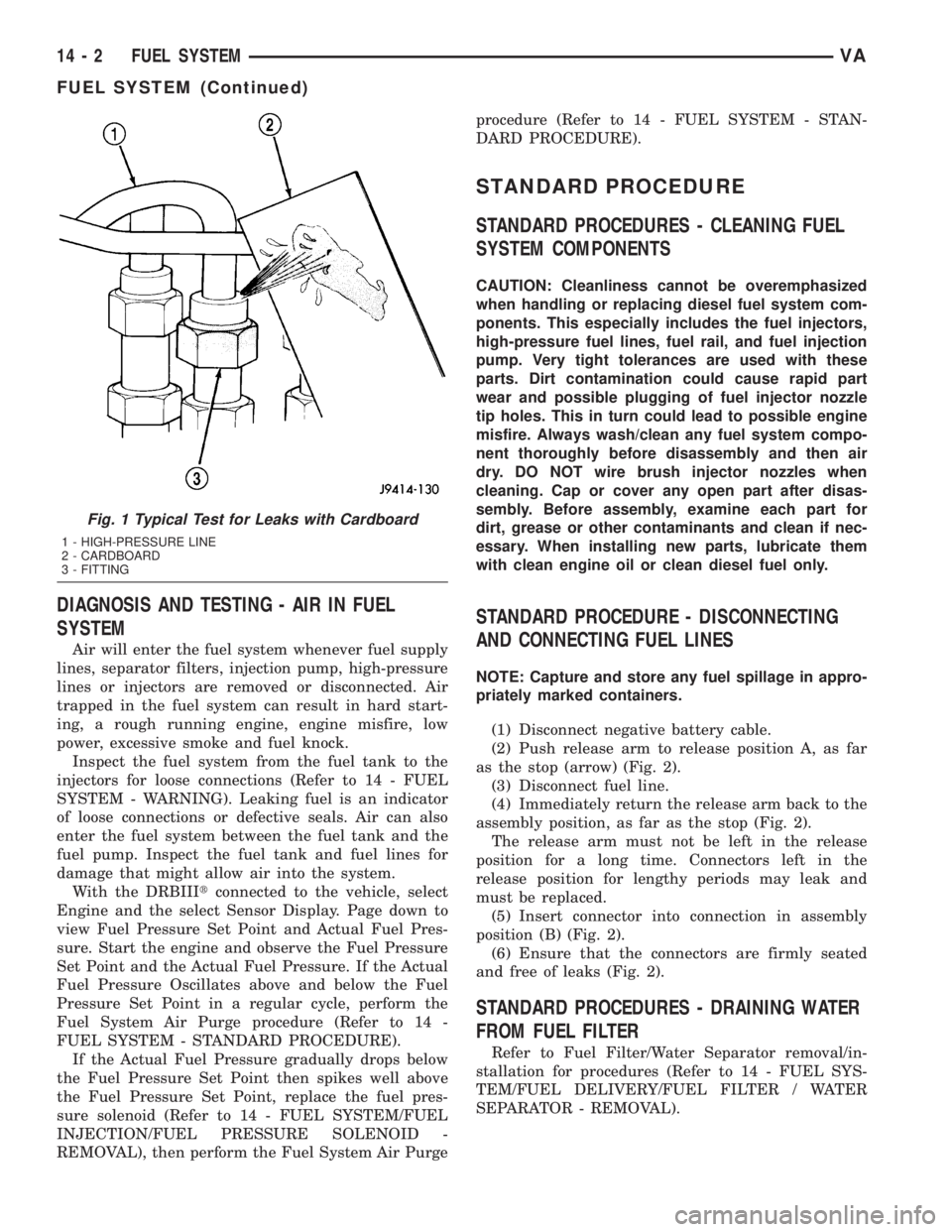
Fig. 1 Typical Test for Leaks with Cardboard
1 - HIGH-PRESSURE LINE
2 - CARDBOARD
3 - FITTING
14 - 2 FUEL SYSTEMVA
FUEL SYSTEM (Continued)
Page 832 of 1232
FUEL DELIVERY
TABLE OF CONTENTS
page page
FUEL DELIVERY
SPECIFICATIONS
TORQUE.............................4
SPECIAL TOOLS
FUEL SYSTEM........................5
FUEL DRAIN TUBES
DIAGNOSIS AND TESTING - FUEL SUPPLY
RESTRICTIONS........................5
FUEL FILTER
DESCRIPTION..........................5
OPERATION............................5
REMOVAL.............................5
INSTALLATION..........................6
FUEL LINES
REMOVAL - HIGH PRESSURE LINES.........6
INSTALLATION - HIGH PRESSURE LINES.....7
FUEL PUMP
DESCRIPTION
DESCRIPTION - HIGH PRESSURE PUMP....7
DESCRIPTION - LOW PRESSURE PUMP....7
OPERATION
OPERATION..........................7
OPERATION - LOW PRESSURE PUMP......8
REMOVAL
REMOVAL - HIGH PRESSURE PUMP.......8
REMOVAL - LOW PRESSURE PUMP.......9INSTALLATION
INSTALLATION - HIGH PRESSURE PUMP . . 10
INSTALLATION - LOW PRESSURE PUMP . . . 11
FUEL RAIL
DESCRIPTION.........................11
OPERATION...........................11
REMOVAL.............................11
INSTALLATION.........................11
FUEL TANK
DESCRIPTION.........................12
REMOVAL.............................12
INSTALLATION.........................13
FUEL TANK MODULE
DESCRIPTION.........................13
REMOVAL.............................13
INSTALLATION.........................14
FUEL LEVEL SENDING UNIT / SENSOR
DESCRIPTION.........................15
REMOVAL.............................15
INSTALLATION.........................15
HI PRESSURE FUEL SHUTOFF SOL
DESCRIPTION.........................16
OPERATION...........................16
WATER IN FUEL SENSOR
DESCRIPTION.........................16
OPERATION...........................16
FUEL DELIVERY
SPECIFICATIONS
TORQUE
DESCRIPTION N´m Ft. Lbs. In. Lbs.
FUEL TANK MOUNTING NUTS 15 - 17 11 - 13 -
FUEL TANK MODULE LOCKRING
(LOCKNUT)45-55 33-41 -
14 - 4 FUEL DELIVERYVA
Page 833 of 1232
SPECIAL TOOLS
FUEL SYSTEM
SPECIAL TOOL CROSS REFERENCE CHART
MB
TOOL #MILLER
TOOL #DESCRIPTION
N/A 5069-2 FUEL GAUGE
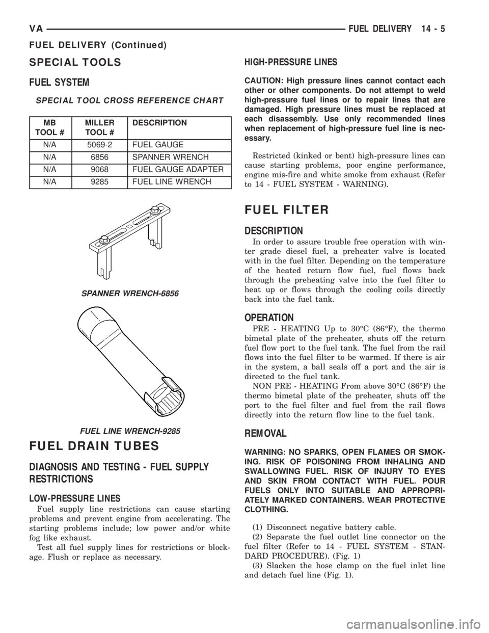
N/A 6856 SPANNER WRENCH
N/A 9068 FUEL GAUGE ADAPTER
N/A 9285 FUEL LINE WRENCH
FUEL DRAIN TUBES
DIAGNOSIS AND TESTING - FUEL SUPPLY
RESTRICTIONS
LOW-PRESSURE LINES
Fuel supply line restrictions can cause starting
problems and prevent engine from accelerating. The
starting problems include; low power and/or white
fog like exhaust.
Test all fuel supply lines for restrictions or block-
age. Flush or replace as necessary.
HIGH-PRESSURE LINES
CAUTION: High pressure lines cannot contact each
other or other components. Do not attempt to weld
high-pressure fuel lines or to repair lines that are
damaged. High pressure lines must be replaced at
each disassembly. Use only recommended lines
when replacement of high-pressure fuel line is nec-
essary.
Restricted (kinked or bent) high-pressure lines can
cause starting problems, poor engine performance,
engine mis-fire and white smoke from exhaust (Refer
to 14 - FUEL SYSTEM - WARNING).
FUEL FILTER
DESCRIPTION
In order to assure trouble free operation with win-
ter grade diesel fuel, a preheater valve is located
with in the fuel filter. Depending on the temperature
of the heated return flow fuel, fuel flows back
through the preheating valve into the fuel filter to
heat up or flows through the cooling coils directly
back into the fuel tank.
OPERATION
PRE - HEATING Up to 30ÉC (86ÉF), the thermo
bimetal plate of the preheater, shuts off the return
fuel flow port to the fuel tank. The fuel from the rail
flows into the fuel filter to be warmed. If there is air
in the system, a ball seals off a port and the air is
directed to the fuel tank.
NON PRE - HEATING From above 30ÉC (86ÉF) the
thermo bimetal plate of the preheater, shuts off the
port to the fuel filter and fuel from the rail flows
directly into the return flow line to the fuel tank.
REMOVAL
WARNING: NO SPARKS, OPEN FLAMES OR SMOK-
ING. RISK OF POISONING FROM INHALING AND
SWALLOWING FUEL. RISK OF INJURY TO EYES
AND SKIN FROM CONTACT WITH FUEL. POUR
FUELS ONLY INTO SUITABLE AND APPROPRI-
ATELY MARKED CONTAINERS. WEAR PROTECTIVE
CLOTHING.
(1) Disconnect negative battery cable.
(2) Separate the fuel outlet line connector on the
fuel filter (Refer to 14 - FUEL SYSTEM - STAN-
DARD PROCEDURE). (Fig. 1)
(3) Slacken the hose clamp on the fuel inlet line
and detach fuel line (Fig. 1).
SPANNER WRENCH-6856
FUEL LINE WRENCH-9285
VAFUEL DELIVERY 14 - 5
FUEL DELIVERY (Continued)
Page 836 of 1232
HIGH PRESSURE SIDE
A. Filling the piston:The piston is moved down
as a result of the piston spring. The fuel supplied by
the fuel delivery pump flows along the ring passage,
the valve disk and the valve spring into the cylinder.
The ball valve prevents the fuel from being able to
flow back from the high pressure passage.
B. Producing high pressure:The piston is
moved up by the rising eccentric shaft and the fuel is
thus compressed. The valve disk shuts off the deliv-
ery volume to the fuel feed. Once the fuel pressure in
the cylinder rises beyond the pressure which exists
in the high pressure circuit, the ball valve opens and
the fuel is pumped into the high pressure circuit.
C. Fuel Temperature RegulationThe ECM can
Interrupt the fuel high pressure delivery of one of the
pump elements in the particle load range in order to
reduce the power required for driving the high pres-
sure pump so as to reduce the fuel temperature. The
pump element is switched off if the fuel temperature
is excessively high (above 278É, 120 bar).
OPERATION - LOW PRESSURE PUMP
The low pressure pump draws fuel from tank
through fuel filter and supplies the high pressure
pump. Fuel pressure at starter speed is 0.4 to 1.5 bar
(6 to 22 psi.). A fuel pressure of 2.0 to 2.5 bar (29 to
36 psi.) is reached at idle speed. Fuel pressure is lim-
ited to 3.5 bar .5 bar (51 psi. 7 psi) by the valve
in the fuel delivery pump. This valve opens by over
coming a spring force and allows excessive fuel to
flow to the intake side of the low pressure pump.
This diverted fuel flows into the return flow pipe
through the fuel cooler back to the tank. As a result
of this circulation, the fuel always remains relatively
cool.
REMOVAL
REMOVAL - HIGH PRESSURE PUMP
(Refer to 14 - FUEL SYSTEM - WARNING)
(1) Disconnect negative battery cable.
(2) Remove viscous fan clutch (Refer to 7 - COOL-
ING/ENGINE/FAN DRIVE VISCOUS CLUTCH -
REMOVAL).
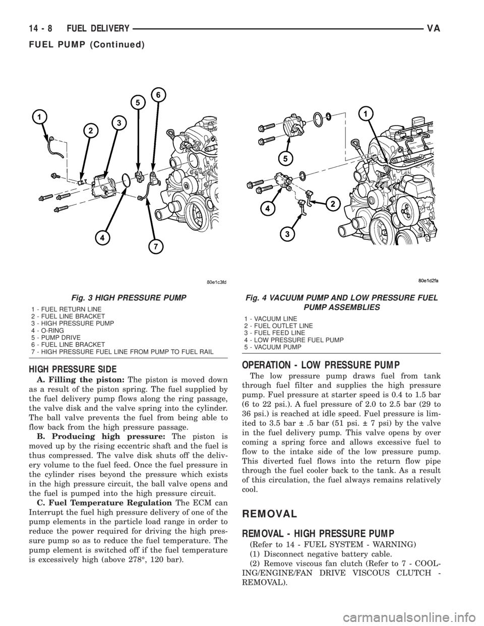
Fig. 3 HIGH PRESSURE PUMP
1 - FUEL RETURN LINE
2 - FUEL LINE BRACKET
3 - HIGH PRESSURE PUMP
4 - O-RING
5 - PUMP DRIVE
6 - FUEL LINE BRACKET
7 - HIGH PRESSURE FUEL LINE FROM PUMP TO FUEL RAIL
Fig. 4 VACUUM PUMP AND LOW PRESSURE FUEL
PUMP ASSEMBLIES
1 - VACUUM LINE
2 - FUEL OUTLET LINE
3 - FUEL FEED LINE
4 - LOW PRESSURE FUEL PUMP
5 - VACUUM PUMP
14 - 8 FUEL DELIVERYVA
FUEL PUMP (Continued)
Page 840 of 1232
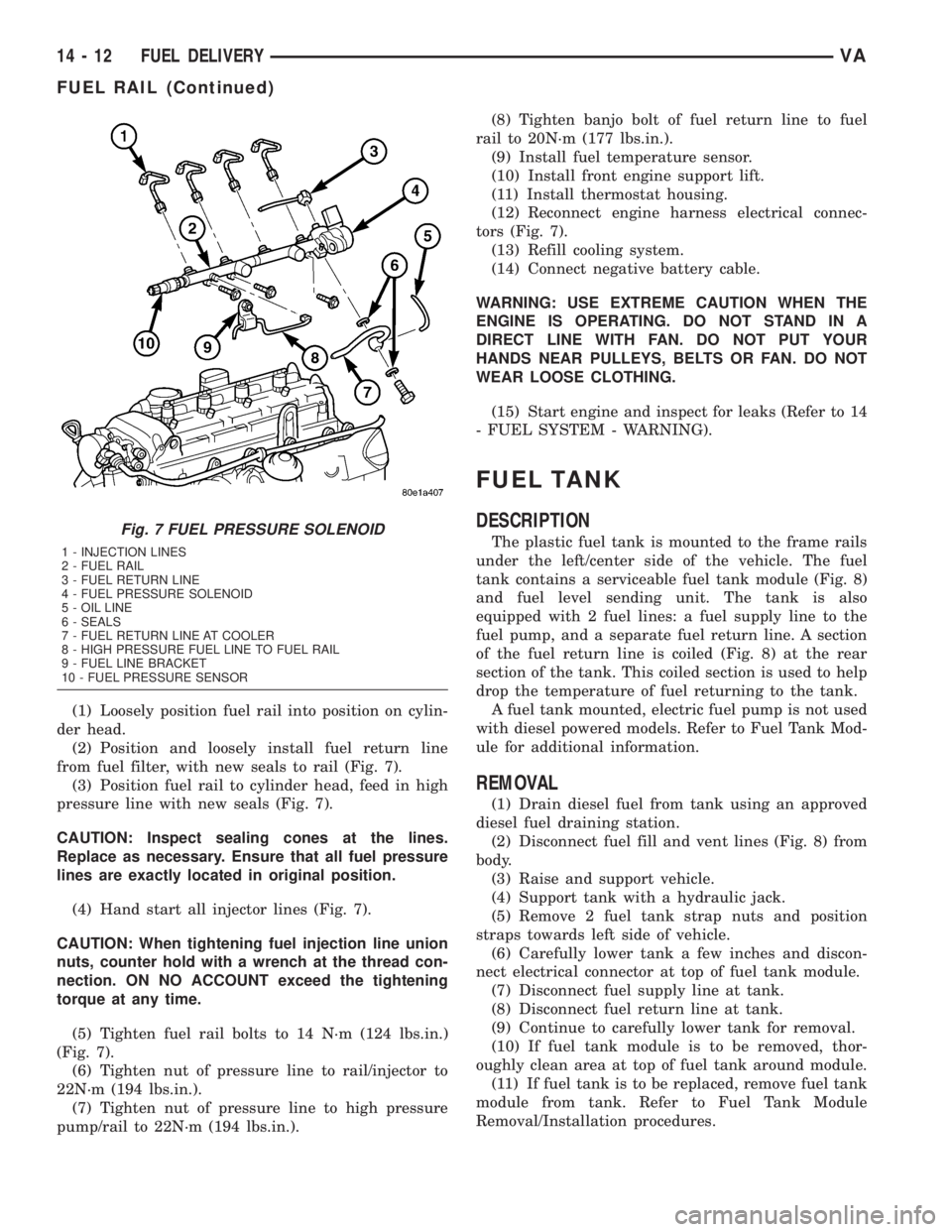
(1) Loosely position fuel rail into position on cylin-
der head.
(2) Position and loosely install fuel return line
from fuel filter, with new seals to rail (Fig. 7).
(3) Position fuel rail to cylinder head, feed in high
pressure line with new seals (Fig. 7).
CAUTION: Inspect sealing cones at the lines.
Replace as necessary. Ensure that all fuel pressure
lines are exactly located in original position.
(4) Hand start all injector lines (Fig. 7).
CAUTION: When tightening fuel injection line union
nuts, counter hold with a wrench at the thread con-
nection. ON NO ACCOUNT exceed the tightening
torque at any time.
(5) Tighten fuel rail bolts to 14 N´m (124 lbs.in.)
(Fig. 7).
(6) Tighten nut of pressure line to rail/injector to
22N´m (194 lbs.in.).
(7) Tighten nut of pressure line to high pressure
pump/rail to 22N´m (194 lbs.in.).(8) Tighten banjo bolt of fuel return line to fuel
rail to 20N´m (177 lbs.in.).
(9) Install fuel temperature sensor.
(10) Install front engine support lift.
(11) Install thermostat housing.
(12) Reconnect engine harness electrical connec-
tors (Fig. 7).
(13) Refill cooling system.
(14) Connect negative battery cable.
WARNING: USE EXTREME CAUTION WHEN THE
ENGINE IS OPERATING. DO NOT STAND IN A
DIRECT LINE WITH FAN. DO NOT PUT YOUR
HANDS NEAR PULLEYS, BELTS OR FAN. DO NOT
WEAR LOOSE CLOTHING.
(15) Start engine and inspect for leaks (Refer to 14
- FUEL SYSTEM - WARNING).
FUEL TANK
DESCRIPTION
The plastic fuel tank is mounted to the frame rails
under the left/center side of the vehicle. The fuel
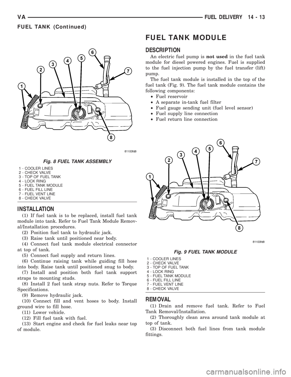
tank contains a serviceable fuel tank module (Fig. 8)
and fuel level sending unit. The tank is also
equipped with 2 fuel lines: a fuel supply line to the
fuel pump, and a separate fuel return line. A section
of the fuel return line is coiled (Fig. 8) at the rear
section of the tank. This coiled section is used to help
drop the temperature of fuel returning to the tank.
A fuel tank mounted, electric fuel pump is not used
with diesel powered models. Refer to Fuel Tank Mod-
ule for additional information.
REMOVAL
(1) Drain diesel fuel from tank using an approved
diesel fuel draining station.
(2) Disconnect fuel fill and vent lines (Fig. 8) from
body.
(3) Raise and support vehicle.
(4) Support tank with a hydraulic jack.
(5) Remove 2 fuel tank strap nuts and position
straps towards left side of vehicle.
(6) Carefully lower tank a few inches and discon-
nect electrical connector at top of fuel tank module.
(7) Disconnect fuel supply line at tank.
(8) Disconnect fuel return line at tank.
(9) Continue to carefully lower tank for removal.
(10) If fuel tank module is to be removed, thor-
oughly clean area at top of fuel tank around module.
(11) If fuel tank is to be replaced, remove fuel tank
module from tank. Refer to Fuel Tank Module
Removal/Installation procedures.
Fig. 7 FUEL PRESSURE SOLENOID
1 - INJECTION LINES
2 - FUEL RAIL
3 - FUEL RETURN LINE
4 - FUEL PRESSURE SOLENOID
5 - OIL LINE
6 - SEALS
7 - FUEL RETURN LINE AT COOLER
8 - HIGH PRESSURE FUEL LINE TO FUEL RAIL
9 - FUEL LINE BRACKET
10 - FUEL PRESSURE SENSOR
14 - 12 FUEL DELIVERYVA
FUEL RAIL (Continued)
Page 841 of 1232
INSTALLATION
(1) If fuel tank is to be replaced, install fuel tank
module into tank. Refer to Fuel Tank Module Remov-
al/Installation procedures.
(2) Position fuel tank to hydraulic jack.
(3) Raise tank until positioned near body.
(4) Connect fuel tank module electrical connector
at top of tank.
(5) Connect fuel supply and return lines.
(6) Continue raising tank while guiding fill hose
into body. Raise tank until positioned snug to body.
(7) Install and position both fuel tank support
straps to mounting studs.
(8) Install 2 fuel tank strap nuts. Refer to Torque
Specifications.
(9) Remove hydraulic jack.
(10) Connect fill and vent hoses to body. Install
ground wire to fill hose.
(11) Lower vehicle.
(12) Fill fuel tank with fuel.
(13) Start engine and check for fuel leaks near top
of module.
FUEL TANK MODULE
DESCRIPTION
An electric fuel pump isnot usedin the fuel tank
module for diesel powered engines. Fuel is supplied
to the fuel injection pump by the fuel transfer (lift)
pump.
The fuel tank module is installed in the top of the
fuel tank (Fig. 9). The fuel tank module contains the
following components:
²Fuel reservoir
²A separate in-tank fuel filter
²Fuel gauge sending unit (fuel level sensor)
²Fuel supply line connection
²Fuel return line connection
REMOVAL
(1) Drain and remove fuel tank. Refer to Fuel
Tank Removal/Installation.
(2) Thoroughly clean area around tank module at
top of tank.
(3) Disconnect both fuel lines from tank module
fittings.
Fig. 8 FUEL TANK ASSEMBLY
1 - COOLER LINES
2 - CHECK VALVE
3 - TOP OF FUEL TANK
4 - LOCK RING
5 - FUEL TANK MODULE
6 - FUEL FILL LINE
7 - FUEL VENT LINE
8 - CHECK VALVE
Fig. 9 FUEL TANK MODULE
1 - COOLER LINES
2 - CHECK VALVE
3 - TOP OF FUEL TANK
4 - LOCK RING
5 - FUEL TANK MODULE
6 - FUEL FILL LINE
7 - FUEL VENT LINE
8 - CHECK VALVE
VAFUEL DELIVERY 14 - 13
FUEL TANK (Continued)
Page 842 of 1232
(4) The plastic fuel tank module locknut (lockring)
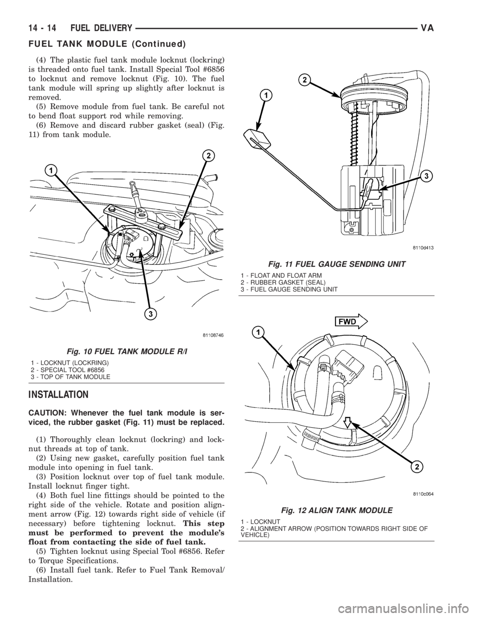
is threaded onto fuel tank. Install Special Tool #6856
to locknut and remove locknut (Fig. 10). The fuel
tank module will spring up slightly after locknut is
removed.
(5) Remove module from fuel tank. Be careful not
to bend float support rod while removing.
(6) Remove and discard rubber gasket (seal) (Fig.
11) from tank module.
INSTALLATION
CAUTION: Whenever the fuel tank module is ser-
viced, the rubber gasket (Fig. 11) must be replaced.
(1) Thoroughly clean locknut (lockring) and lock-
nut threads at top of tank.
(2) Using new gasket, carefully position fuel tank
module into opening in fuel tank.
(3) Position locknut over top of fuel tank module.
Install locknut finger tight.
(4) Both fuel line fittings should be pointed to the
right side of the vehicle. Rotate and position align-
ment arrow (Fig. 12) towards right side of vehicle (if
necessary) before tightening locknut.This step
must be performed to prevent the module's
float from contacting the side of fuel tank.
(5) Tighten locknut using Special Tool #6856. Refer
to Torque Specifications.
(6) Install fuel tank. Refer to Fuel Tank Removal/
Installation.
Fig. 10 FUEL TANK MODULE R/I
1 - LOCKNUT (LOCKRING)
2 - SPECIAL TOOL #6856
3 - TOP OF TANK MODULE
Fig. 11 FUEL GAUGE SENDING UNIT
1 - FLOAT AND FLOAT ARM
2 - RUBBER GASKET (SEAL)
3 - FUEL GAUGE SENDING UNIT
Fig. 12 ALIGN TANK MODULE
1 - LOCKNUT
2 - ALIGNMENT ARROW (POSITION TOWARDS RIGHT SIDE OF
VEHICLE)
14 - 14 FUEL DELIVERYVA
FUEL TANK MODULE (Continued)
Page 843 of 1232
FUEL LEVEL SENDING UNIT /
SENSOR
DESCRIPTION
The fuel gauge sending unit (fuel level sensor) is
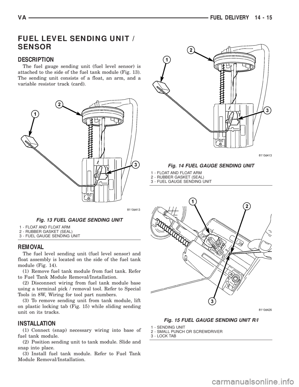
attached to the side of the fuel tank module (Fig. 13).
The sending unit consists of a float, an arm, and a
variable resistor track (card).
REMOVAL
The fuel level sending unit (fuel level sensor) and
float assembly is located on the side of the fuel tank
module (Fig. 14).
(1) Remove fuel tank module from fuel tank. Refer
to Fuel Tank Module Removal/Installation.
(2) Disconnect wiring from fuel tank module base
using a terminal pick / removal tool. Refer to Special
Tools in 8W, Wiring for tool part numbers.
(3) To remove sending unit from tank module, lift
on plastic locking tab (Fig. 15) while sliding sending
unit on its tracks.
INSTALLATION
(1) Connect (snap) necessary wiring into base of
fuel tank module.
(2) Position sending unit to tank module. Slide and
snap into place.
(3) Install fuel tank module. Refer to Fuel Tank
Module Removal/Installation.
Fig. 13 FUEL GAUGE SENDING UNIT
1 - FLOAT AND FLOAT ARM
2 - RUBBER GASKET (SEAL)
3 - FUEL GAUGE SENDING UNIT
Fig. 14 FUEL GAUGE SENDING UNIT
1 - FLOAT AND FLOAT ARM
2 - RUBBER GASKET (SEAL)
3 - FUEL GAUGE SENDING UNIT
Fig. 15 FUEL GAUGE SENDING UNIT R/I
1 - SENDING UNIT
2 - SMALL PUNCH OR SCREWDRIVER
3 - LOCK TAB
VAFUEL DELIVERY 14 - 15