2005 MERCEDES-BENZ SPRINTER sliding
[x] Cancel search: slidingPage 70 of 1232
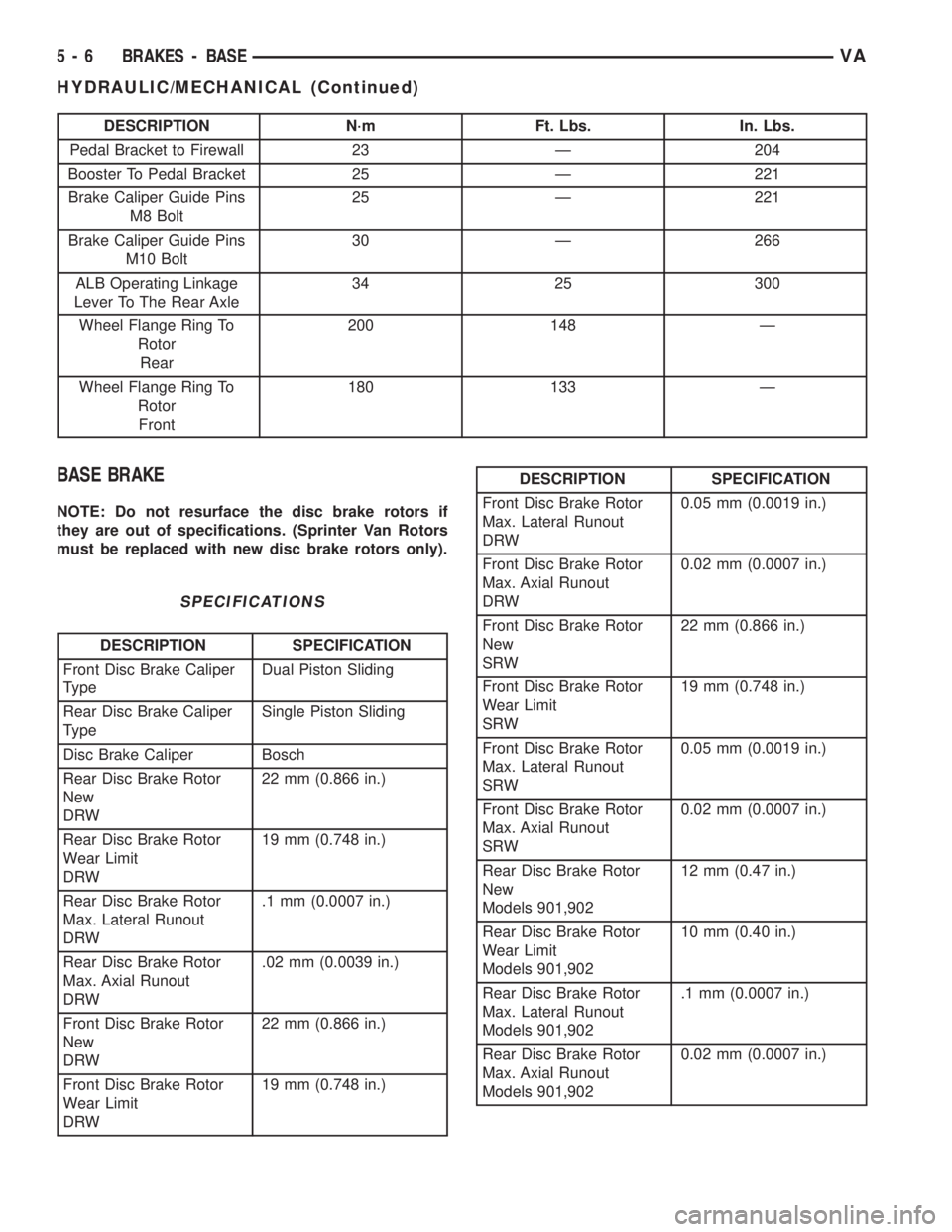
DESCRIPTION N´m Ft. Lbs. In. Lbs.
Pedal Bracket to Firewall 23 Ð 204
Booster To Pedal Bracket 25 Ð 221
Brake Caliper Guide Pins
M8 Bolt25 Ð 221
Brake Caliper Guide Pins
M10 Bolt30 Ð 266
ALB Operating Linkage
Lever To The Rear Axle34 25 300
Wheel Flange Ring To
Rotor
Rear200 148 Ð
Wheel Flange Ring To
Rotor
Front180 133 Ð
BASE BRAKE
NOTE: Do not resurface the disc brake rotors if
they are out of specifications. (Sprinter Van Rotors
must be replaced with new disc brake rotors only).
SPECIFICATIONS
DESCRIPTION SPECIFICATION
Front Disc Brake Caliper
TypeDual Piston Sliding
Rear Disc Brake Caliper
TypeSingle Piston Sliding
Disc Brake Caliper Bosch
Rear Disc Brake Rotor
New
DRW22 mm (0.866 in.)
Rear Disc Brake Rotor
Wear Limit
DRW19 mm (0.748 in.)
Rear Disc Brake Rotor
Max. Lateral Runout
DRW.1 mm (0.0007 in.)
Rear Disc Brake Rotor
Max. Axial Runout
DRW.02 mm (0.0039 in.)
Front Disc Brake Rotor
New
DRW22 mm (0.866 in.)
Front Disc Brake Rotor
Wear Limit
DRW19 mm (0.748 in.)
DESCRIPTION SPECIFICATION
Front Disc Brake Rotor
Max. Lateral Runout
DRW0.05 mm (0.0019 in.)
Front Disc Brake Rotor
Max. Axial Runout
DRW0.02 mm (0.0007 in.)
Front Disc Brake Rotor
New
SRW22 mm (0.866 in.)
Front Disc Brake Rotor
Wear Limit
SRW19 mm (0.748 in.)
Front Disc Brake Rotor
Max. Lateral Runout
SRW0.05 mm (0.0019 in.)
Front Disc Brake Rotor
Max. Axial Runout
SRW0.02 mm (0.0007 in.)
Rear Disc Brake Rotor
New
Models 901,90212 mm (0.47 in.)
Rear Disc Brake Rotor
Wear Limit
Models 901,90210 mm (0.40 in.)
Rear Disc Brake Rotor
Max. Lateral Runout
Models 901,902.1 mm (0.0007 in.)
Rear Disc Brake Rotor
Max. Axial Runout
Models 901,9020.02 mm (0.0007 in.)
5 - 6 BRAKES - BASEVA
HYDRAULIC/MECHANICAL (Continued)
Page 122 of 1232
OPERATION
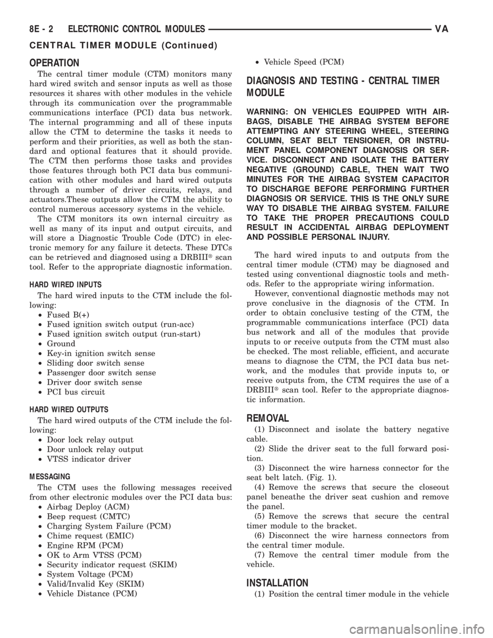
The central timer module (CTM) monitors many
hard wired switch and sensor inputs as well as those
resources it shares with other modules in the vehicle
through its communication over the programmable
communications interface (PCI) data bus network.
The internal programming and all of these inputs
allow the CTM to determine the tasks it needs to
perform and their priorities, as well as both the stan-
dard and optional features that it should provide.
The CTM then performs those tasks and provides
those features through both PCI data bus communi-
cation with other modules and hard wired outputs
through a number of driver circuits, relays, and
actuators.These outputs allow the CTM the ability to
control numerous accessory systems in the vehicle.
The CTM monitors its own internal circuitry as
well as many of its input and output circuits, and
will store a Diagnostic Trouble Code (DTC) in elec-
tronic memory for any failure it detects. These DTCs
can be retrieved and diagnosed using a DRBIIItscan
tool. Refer to the appropriate diagnostic information.
HARD WIRED INPUTS
The hard wired inputs to the CTM include the fol-
lowing:
²Fused B(+)
²Fused ignition switch output (run-acc)
²Fused ignition switch output (run-start)
²Ground
²Key-in ignition switch sense
²Sliding door switch sense
²Passenger door switch sense
²Driver door switch sense
²PCI bus circuit
HARD WIRED OUTPUTS
The hard wired outputs of the CTM include the fol-
lowing:
²Door lock relay output
²Door unlock relay output
²VTSS indicator driver
MESSAGING
The CTM uses the following messages received
from other electronic modules over the PCI data bus:
²Airbag Deploy (ACM)
²Beep request (CMTC)
²Charging System Failure (PCM)
²Chime request (EMIC)
²Engine RPM (PCM)
²OK to Arm VTSS (PCM)
²Security indicator request (SKIM)
²System Voltage (PCM)
²Valid/Invalid Key (SKIM)
²Vehicle Distance (PCM)²Vehicle Speed (PCM)DIAGNOSIS AND TESTING - CENTRAL TIMER
MODULE
WARNING: ON VEHICLES EQUIPPED WITH AIR-
BAGS, DISABLE THE AIRBAG SYSTEM BEFORE
ATTEMPTING ANY STEERING WHEEL, STEERING
COLUMN, SEAT BELT TENSIONER, OR INSTRU-
MENT PANEL COMPONENT DIAGNOSIS OR SER-
VICE. DISCONNECT AND ISOLATE THE BATTERY
NEGATIVE (GROUND) CABLE, THEN WAIT TWO
MINUTES FOR THE AIRBAG SYSTEM CAPACITOR
TO DISCHARGE BEFORE PERFORMING FURTHER
DIAGNOSIS OR SERVICE. THIS IS THE ONLY SURE
WAY TO DISABLE THE AIRBAG SYSTEM. FAILURE
TO TAKE THE PROPER PRECAUTIONS COULD
RESULT IN ACCIDENTAL AIRBAG DEPLOYMENT
AND POSSIBLE PERSONAL INJURY.
The hard wired inputs to and outputs from the
central timer module (CTM) may be diagnosed and
tested using conventional diagnostic tools and meth-
ods. Refer to the appropriate wiring information.
However, conventional diagnostic methods may not
prove conclusive in the diagnosis of the CTM. In
order to obtain conclusive testing of the CTM, the
programmable communications interface (PCI) data
bus network and all of the modules that provide
inputs to or receive outputs from the CTM must also
be checked. The most reliable, efficient, and accurate
means to diagnose the CTM, the PCI data bus net-
work, and the modules that provide inputs to, or
receive outputs from, the CTM requires the use of a
DRBIIItscan tool. Refer to the appropriate diagnos-
tic information.
REMOVAL
(1) Disconnect and isolate the battery negative
cable.
(2) Slide the driver seat to the full forward posi-
tion.
(3) Disconnect the wire harness connector for the
seat belt latch. (Fig. 1).
(4) Remove the screws that secure the closeout
panel beneathe the driver seat cushion and remove
the panel.
(5) Remove the screws that secure the central
timer module to the bracket.
(6) Disconnect the wire harness connectors from
the central timer module.
(7) Remove the central timer module from the
vehicle.
INSTALLATION
(1) Position the central timer module in the vehicle
8E - 2 ELECTRONIC CONTROL MODULESVA
CENTRAL TIMER MODULE (Continued)
Page 224 of 1232
A door jamb switch for each sliding side door and the
right rear door is standard equipment on wagon mod-
els. The sliding and rear door jamb switches are not
available for van models.
²Entry/Exit Lamp- An entry/exit lamp to illu-
minate each front and sliding side door step well is
optional equipment on wagon models.
²Time Delay Relay- Vehicles equipped with the
optional remote cargo lamp switches also have a time
delay relay located in the electrical center within the
driver side front seat riser.
Hard wired circuitry connects the interior lighting
system components to the electrical system of the
vehicle. These hard wired circuits are integral to sev-
eral wire harnesses, which are routed throughout the
vehicle and retained by many different methods.
These circuits may be connected to each other, to the
vehicle electrical system and to the interior lighting
system components through the use of a combination
of soldered splices, splice block connectors, and many
different types of wire harness terminal connectors
and insulators. Refer to the appropriate wiring infor-
mation. The wiring information includes wiring dia-
grams, proper wire and connector repair procedures,
further details on wire harness routing and reten-
tion, as well as pin-out and location views for the
various wire harness connectors, splices and grounds.
OPERATION
The interior lighting systems can be divided into
two general classifications based upon the circuit
that controls their operation: The interior lighting
circuit, or the exterior lighting circuit. The hard
wired circuits and components of the interior lighting
systems may be diagnosed and tested using conven-
tional diagnostic tools and procedures.
INTERIOR LIGHTING CIRCUIT
Depending upon the vehicle model (van or wagon)
and the selected vehicle options the interior lighting
circuit may include dome/cargo lamps located over-
head in the front and rear of the vehicle, a dome/
reading lamp located in the header area above the
windshield between the sun visors, and entry/exit
lamps located in the front and sliding side door step
wells.
WAGON MODELS
In all wagon models, the lamps in the interior
lighting circuit are provided with battery current at
all times by a fuse in the fuse block beneath the
steering column. The front, side, and rear door jamb
switches control a ground path for each of these
lamps, except for the optional reading lamp. If the
lamp has an optional integral switch, that switch has
three separate positions. The first position provides aground path independent of the door jamb switches
to turn the lamp On. The second, or center position
allows the door jamb switches to control the lamp.
The third position segregates that lamp from the
door jamb switch input, turning the lamp Off. In the
case of the optional dome/reading lamp, the integral
lamp switch has a fourth position which will illumi-
nate only the reading lamp bulb.
VAN MODELS
Unless a van model is equipped with an optional
remote cargo lamp switch, all of the lamps in the
interior lighting circuit operate the same way as the
wagon models except that there are only two door
jamb switches, one for each front door. If the vehicle
is equipped with an optional remote cargo lamp
switch, the lamps in the rear of the vehicle on the
interior lighting circuit are provided with battery
current by the time delay relay. The time delay relay
is a smart relay containing active electronic elements
that comprise an electronic timer logic circuit. When
the remote cargo lamp switches provide the proper
input to the time delay relay, the relay logic responds
by energizing the relay control coil. The energized
relay control coil provides battery current to all of
the lamps on the rear interior lighting circuit and to
the indicator Light-Emitting Diode (LED) units in
the remote cargo switches causing each to illuminate.
If a remote cargo lamp switch remains On for more
than about fifteen minutes, the time delay relay will
then automatically de-energize the rear interior
lighting circuits until the remote cargo lamp switch
is cycled Off and then back On.
EXTERIOR LIGHTING CIRCUIT
The exterior lighting circuit provides battery cur-
rent to the optional ash receiver/cigar lighter lamp
and to the illumination Light-Emitting Diode (LED)
unit within the remote cargo lamp switch in the
instrument panel accessory switch bezel whenever
the exterior lamps are turned On.
SPECIFICATIONS - INTERIOR LIGHTING
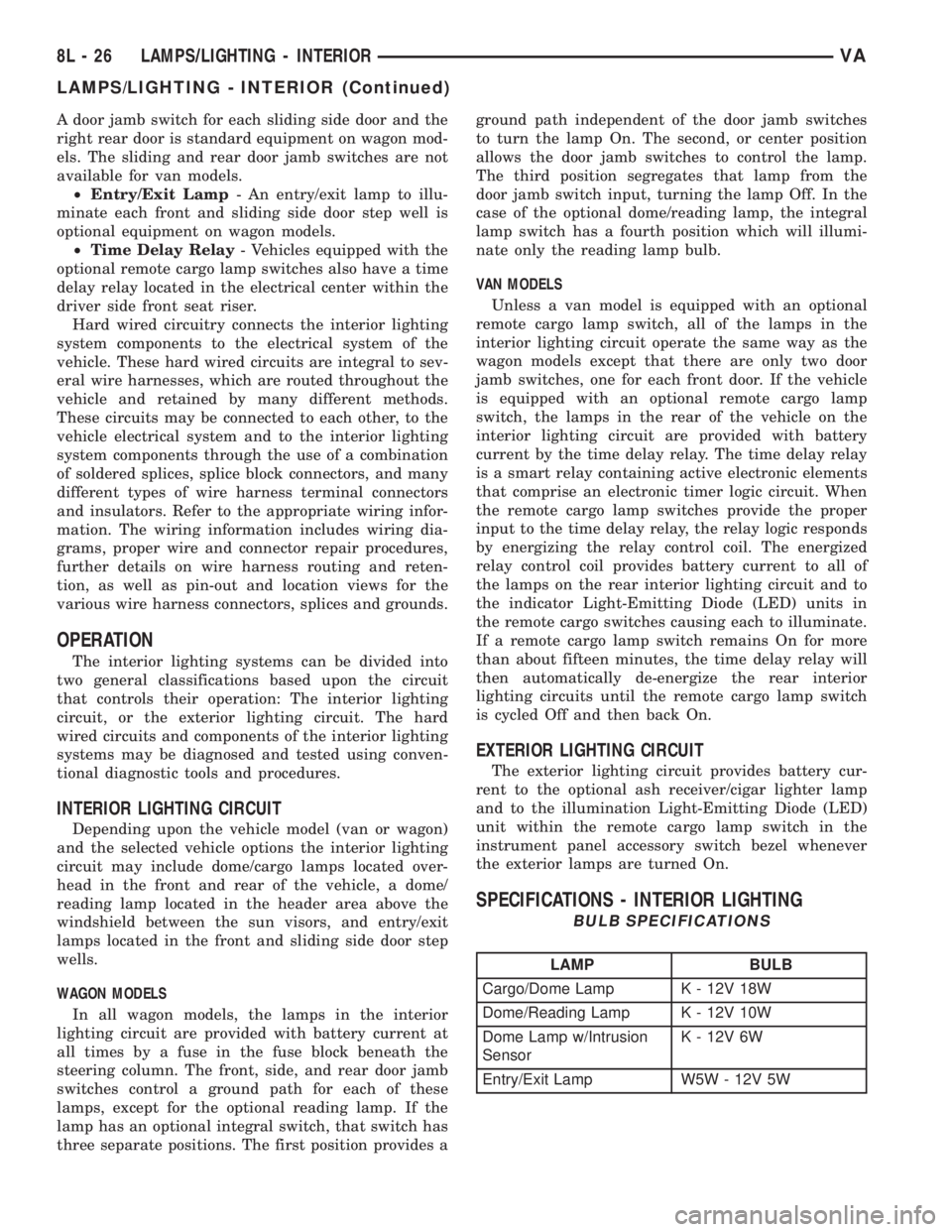
BULB SPECIFICATIONS
LAMP BULB
Cargo/Dome Lamp K - 12V 18W
Dome/Reading Lamp K - 12V 10W
Dome Lamp w/Intrusion
SensorK - 12V 6W
Entry/Exit Lamp W5W - 12V 5W
8L - 26 LAMPS/LIGHTING - INTERIORVA
LAMPS/LIGHTING - INTERIOR (Continued)
Page 313 of 1232
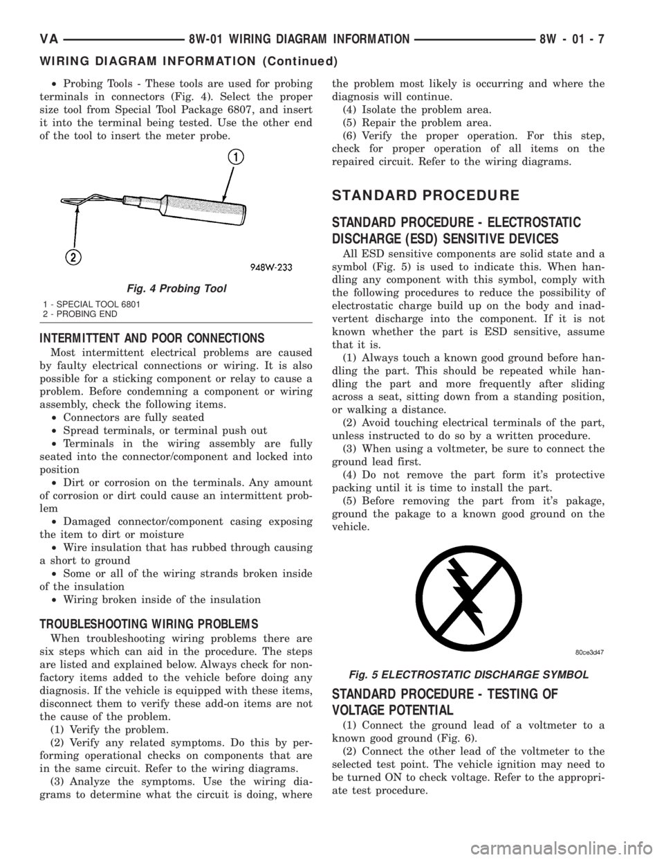
²Probing Tools - These tools are used for probing
terminals in connectors (Fig. 4). Select the proper
size tool from Special Tool Package 6807, and insert
it into the terminal being tested. Use the other end
of the tool to insert the meter probe.
INTERMITTENT AND POOR CONNECTIONS
Most intermittent electrical problems are caused
by faulty electrical connections or wiring. It is also
possible for a sticking component or relay to cause a
problem. Before condemning a component or wiring
assembly, check the following items.
²Connectors are fully seated
²Spread terminals, or terminal push out
²Terminals in the wiring assembly are fully
seated into the connector/component and locked into
position
²Dirt or corrosion on the terminals. Any amount
of corrosion or dirt could cause an intermittent prob-
lem
²Damaged connector/component casing exposing
the item to dirt or moisture
²Wire insulation that has rubbed through causing
a short to ground
²Some or all of the wiring strands broken inside
of the insulation
²Wiring broken inside of the insulation
TROUBLESHOOTING WIRING PROBLEMS
When troubleshooting wiring problems there are
six steps which can aid in the procedure. The steps
are listed and explained below. Always check for non-
factory items added to the vehicle before doing any
diagnosis. If the vehicle is equipped with these items,
disconnect them to verify these add-on items are not
the cause of the problem.
(1) Verify the problem.
(2) Verify any related symptoms. Do this by per-
forming operational checks on components that are
in the same circuit. Refer to the wiring diagrams.
(3) Analyze the symptoms. Use the wiring dia-
grams to determine what the circuit is doing, wherethe problem most likely is occurring and where the
diagnosis will continue.
(4) Isolate the problem area.
(5) Repair the problem area.
(6) Verify the proper operation. For this step,
check for proper operation of all items on the
repaired circuit. Refer to the wiring diagrams.
STANDARD PROCEDURE
STANDARD PROCEDURE - ELECTROSTATIC
DISCHARGE (ESD) SENSITIVE DEVICES
All ESD sensitive components are solid state and a
symbol (Fig. 5) is used to indicate this. When han-
dling any component with this symbol, comply with
the following procedures to reduce the possibility of
electrostatic charge build up on the body and inad-
vertent discharge into the component. If it is not
known whether the part is ESD sensitive, assume
that it is.
(1) Always touch a known good ground before han-
dling the part. This should be repeated while han-
dling the part and more frequently after sliding
across a seat, sitting down from a standing position,
or walking a distance.
(2) Avoid touching electrical terminals of the part,
unless instructed to do so by a written procedure.
(3) When using a voltmeter, be sure to connect the
ground lead first.
(4) Do not remove the part form it's protective
packing until it is time to install the part.
(5) Before removing the part from it's pakage,
ground the pakage to a known good ground on the
vehicle.
STANDARD PROCEDURE - TESTING OF
VOLTAGE POTENTIAL
(1) Connect the ground lead of a voltmeter to a
known good ground (Fig. 6).
(2) Connect the other lead of the voltmeter to the
selected test point. The vehicle ignition may need to
be turned ON to check voltage. Refer to the appropri-
ate test procedure.
Fig. 4 Probing Tool
1 - SPECIAL TOOL 6801
2 - PROBING END
Fig. 5 ELECTROSTATIC DISCHARGE SYMBOL
VA8W-01 WIRING DIAGRAM INFORMATION 8W - 01 - 7
WIRING DIAGRAM INFORMATION (Continued)
Page 319 of 1232
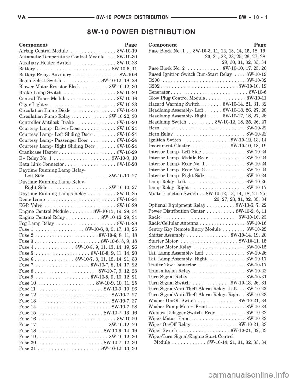
8W-10 POWER DISTRIBUTION
Component Page
Airbag Control Module................ 8W-10-19
Automatic Temperature Control Module . . . 8W-10-30
Auxiliary Heater Switch............... 8W-10-23
Battery.......................... 8W-10-6, 11
Battery Relay- Auxiliary................ 8W-10-6
Beam Select Switch............. 8W-10-12, 18, 28
Blower Motor Resistor Block......... 8W-10-12, 30
Brake Lamp Switch.................. 8W-10-20
Central Timer Module................. 8W-10-16
Cigar Lighter....................... 8W-10-23
Circulation Pump Diode............... 8W-10-30
Circulation Pump Relay............. 8W-10-22, 30
Controller Antilock Brake.............. 8W-10-20
Courtesy Lamp- Driver Door............ 8W-10-24
Courtesy Lamp- Left Sliding Door........ 8W-10-24
Courtesy Lamp- Passenger Door......... 8W-10-24
Courtesy Lamp- Right Sliding Door....... 8W-10-24
Crankcase Heater.................... 8W-10-29
D+ Relay No. 1.................... 8W-10-9, 10
Data Link Connector.................. 8W-10-20
Daytime Running Lamp Relay-
Left Side...................... 8W-10-10, 27
Daytime Running Lamp Relay-
Right Side..................... 8W-10-10, 27
Daytime Running Lamps Relay.......... 8W-10-25
Dome Lamp........................ 8W-10-24
EGR Valve......................... 8W-10-29
Engine Control Module........ 8W-10-15, 19, 29, 34
Engine Control Relay............ 8W-10-12, 29, 34
Fog Lamp Relay..................... 8W-10-28
Fuse 1................. 8W-10-6, 8, 9, 17, 18, 25
Fuse 2...................... 8W-10-6, 8, 11, 18
Fuse 3....................... 8W-10-6, 8, 9, 18
Fuse 4.............. 8W-10-8, 9, 11, 13, 14, 19, 26
Fuse 5................... 8W-10-8, 9, 11, 14, 20
Fuse 6.............. 8W-10-7, 8, 11, 12, 14, 21, 33
Fuse 7................... 8W-10-7, 8, 14, 17, 22
Fuse 8...................... 8W-10-7, 9, 12, 23
Fuse 9................... 8W-10-8, 9, 10, 12, 21
Fuse 10.................... 8W-10-9, 10, 11, 25
Fuse 11....................... 8W-10-9, 10, 26
Fuse 12......................... 8W-10-7, 27
Fuse 13......................... 8W-10-7, 27
Fuse 14......................... 8W-10-7, 28
Fuse 15....................... 8W-10-7, 13, 16
Fuse 16........................... 8W-10-29
Fuse 17......................... 8W-10-12, 29
Fuse 18....................... 8W-10-9, 14, 19
Fuse 19......................... 8W-10-12, 30
Fuse 20....................... 8W-10-7, 12, 30
Fuse 21...................... 8W-10-12, 13, 30
Component Page
Fuse Block No. 1 . . 8W-10-3, 11, 12, 13, 14, 15, 18, 19,
20, 21, 22, 23, 25, 26, 27, 28,
29, 30, 31, 32, 33, 34
Fuse Block No. 2............ 8W-10-10, 17, 25, 26
Fused Ignition Switch Run-Start Relay.... 8W-10-19
G200............................. 8W-10-32
G202........................... 8W-10-10, 19
Generator........................... 8W-10-6
Glow Plug Control Module.............. 8W-10-11
Hazard Warning Switch....... 8W-10-14, 21, 31, 32
Headlamp Assembly- Left...... 8W-10-18, 26, 27, 28
Headlamp Assembly- Right..... 8W-10-17, 18, 27, 28
Headlamp Switch......... 8W-10-12, 18, 25, 26, 27
Horn............................. 8W-10-22
Horn Relay......................... 8W-10-22
Ignition Switch................ 8W-10-12, 13, 14
Instrument Cluster............. 8W-10-10, 18, 19
Interior Lamp- Left Side............... 8W-10-24
Interior Lamp- Middle Rear............ 8W-10-24
Interior Lamp- Rear No. 1.............. 8W-10-24
Interior Lamp- Rear No. 2.............. 8W-10-24
Interior Lamp- Right Side.............. 8W-10-24
Lamp Relay- Left.................... 8W-10-26
Lamp Relay- Right................... 8W-10-17
Multi- Function Switch . . 8W-10-12, 13, 14, 18, 21, 25,
26, 27, 28, 31, 32, 33, 34
Optional Equipment Relay.......... 8W-10-6, 7, 22
Power Distribution Center.......... 8W-10-2, 6, 11
Radio.......................... 8W-10-16, 23
Radio/Cellular Antenna................ 8W-10-16
Sentry Key Remote Entry Module........ 8W-10-22
Shifter Assembly............... 8W-10-14, 19, 20
Starter Motor.................... 8W-10-11, 15
Starter Motor Relay.................. 8W-10-15
Tail Lamp Assembly- Left.............. 8W-10-26
Tail Lamp Assembly- Right............. 8W-10-17
Trailer Tow Connector................. 8W-10-17
Transmission Relay................... 8W-10-22
Turn Signal Relay.................... 8W-10-31
Turn Signal Switch............. 8W-10-13, 26, 31
Turn Signal/Anti-Theft Alarm Relay- Left . . 8W-10-23
Turn Signal/Anti-Theft Alarm Relay- Right . 8W-10-23
Washer On/Off Switch.............. 8W-10-21, 34
Washer Pump Motor- Front............. 8W-10-34
Window Defogger Switch- Rear.......... 8W-10-22
Wiper Motor- Front................... 8W-10-33
Wiper On/Off Relay................ 8W-10-21, 33
Wiper Switch.................. 8W-10-21, 32, 33
Wiper/Turn Signal/Engine Start Control
Module............ 8W-10-14, 21, 31, 32, 33, 34
VA8W-10 POWER DISTRIBUTION 8W - 10 - 1
Page 475 of 1232
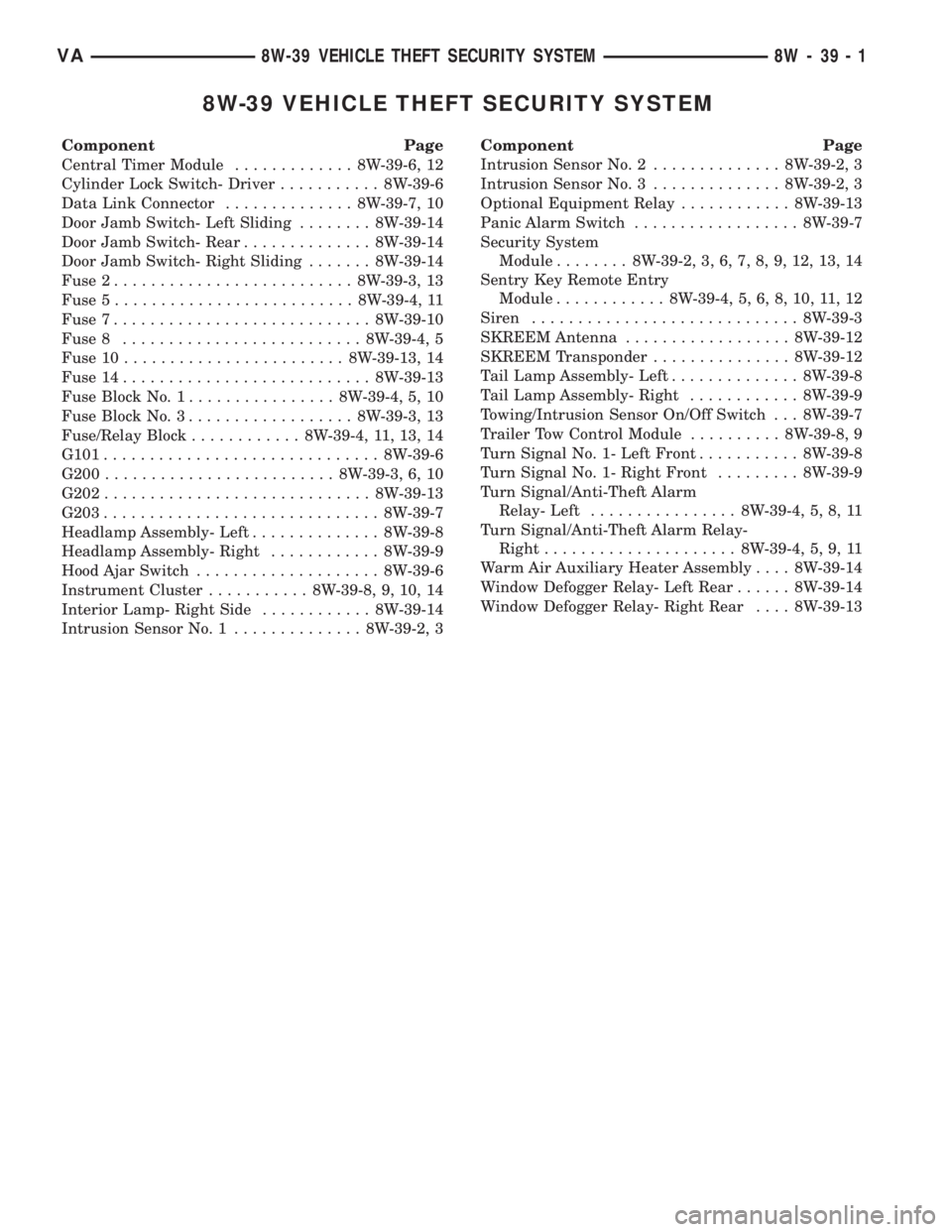
8W-39 VEHICLE THEFT SECURITY SYSTEM
Component Page
Central Timer Module............. 8W-39-6, 12
Cylinder Lock Switch- Driver........... 8W-39-6
Data Link Connector.............. 8W-39-7, 10
Door Jamb Switch- Left Sliding........ 8W-39-14
Door Jamb Switch- Rear.............. 8W-39-14
Door Jamb Switch- Right Sliding....... 8W-39-14
Fuse 2.......................... 8W-39-3, 13
Fuse 5.......................... 8W-39-4, 11
Fuse 7............................ 8W-39-10
Fuse 8.......................... 8W-39-4, 5
Fuse 10........................ 8W-39-13, 14
Fuse 14........................... 8W-39-13
Fuse Block No. 1................ 8W-39-4, 5, 10
Fuse Block No. 3.................. 8W-39-3, 13
Fuse/Relay Block............ 8W-39-4, 11, 13, 14
G101.............................. 8W-39-6
G200......................... 8W-39-3, 6, 10
G202............................. 8W-39-13
G203.............................. 8W-39-7
Headlamp Assembly- Left.............. 8W-39-8
Headlamp Assembly- Right............ 8W-39-9
Hood Ajar Switch.................... 8W-39-6
Instrument Cluster........... 8W-39-8, 9, 10, 14
Interior Lamp- Right Side............ 8W-39-14
Intrusion Sensor No. 1.............. 8W-39-2, 3Component Page
Intrusion Sensor No. 2.............. 8W-39-2, 3
Intrusion Sensor No. 3.............. 8W-39-2, 3
Optional Equipment Relay............ 8W-39-13
Panic Alarm Switch.................. 8W-39-7
Security System
Module........ 8W-39-2, 3, 6, 7, 8, 9, 12, 13, 14
Sentry Key Remote Entry
Module............ 8W-39-4, 5, 6, 8, 10, 11, 12
Siren............................. 8W-39-3
SKREEM Antenna.................. 8W-39-12
SKREEM Transponder............... 8W-39-12
Tail Lamp Assembly- Left.............. 8W-39-8
Tail Lamp Assembly- Right............ 8W-39-9
Towing/Intrusion Sensor On/Off Switch . . . 8W-39-7
Trailer Tow Control Module.......... 8W-39-8, 9
Turn Signal No. 1- Left Front........... 8W-39-8
Turn Signal No. 1- Right Front......... 8W-39-9
Turn Signal/Anti-Theft Alarm
Relay- Left................ 8W-39-4, 5, 8, 11
Turn Signal/Anti-Theft Alarm Relay-
Right..................... 8W-39-4, 5, 9, 11
Warm Air Auxiliary Heater Assembly.... 8W-39-14
Window Defogger Relay- Left Rear...... 8W-39-14
Window Defogger Relay- Right Rear.... 8W-39-13
VA8W-39 VEHICLE THEFT SECURITY SYSTEM 8W - 39 - 1
Page 529 of 1232
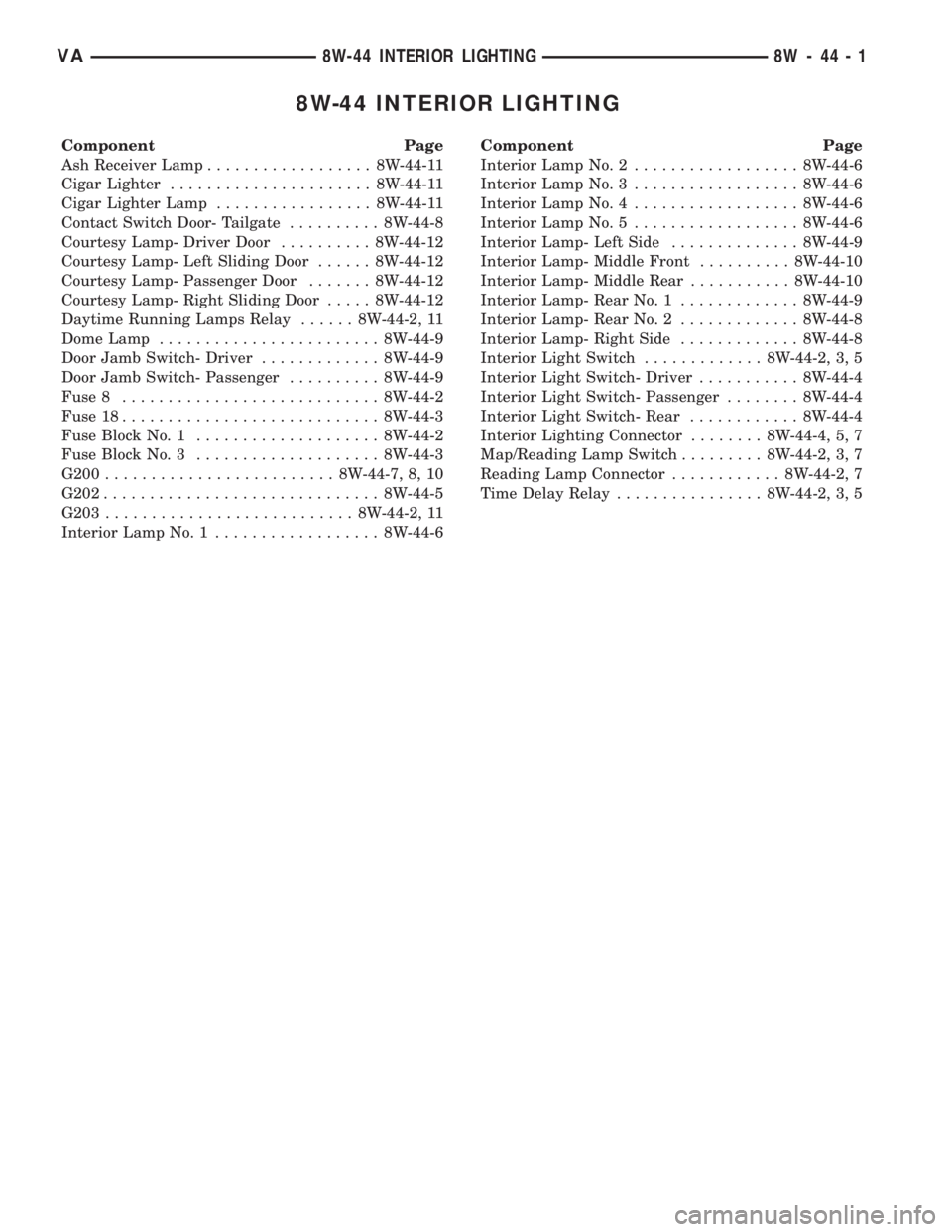
8W-44 INTERIOR LIGHTING
Component Page
Ash Receiver Lamp.................. 8W-44-11
Cigar Lighter...................... 8W-44-11
Cigar Lighter Lamp................. 8W-44-11
Contact Switch Door- Tailgate.......... 8W-44-8
Courtesy Lamp- Driver Door.......... 8W-44-12
Courtesy Lamp- Left Sliding Door...... 8W-44-12
Courtesy Lamp- Passenger Door....... 8W-44-12
Courtesy Lamp- Right Sliding Door..... 8W-44-12
Daytime Running Lamps Relay...... 8W-44-2, 11
Dome Lamp........................ 8W-44-9
Door Jamb Switch- Driver............. 8W-44-9
Door Jamb Switch- Passenger.......... 8W-44-9
Fuse 8............................ 8W-44-2
Fuse 18............................ 8W-44-3
Fuse Block No. 1.................... 8W-44-2
Fuse Block No. 3.................... 8W-44-3
G200......................... 8W-44-7, 8, 10
G202.............................. 8W-44-5
G203........................... 8W-44-2, 11
Interior Lamp No. 1.................. 8W-44-6Component Page
Interior Lamp No. 2.................. 8W-44-6
Interior Lamp No. 3.................. 8W-44-6
Interior Lamp No. 4.................. 8W-44-6
Interior Lamp No. 5.................. 8W-44-6
Interior Lamp- Left Side.............. 8W-44-9
Interior Lamp- Middle Front.......... 8W-44-10
Interior Lamp- Middle Rear........... 8W-44-10
Interior Lamp- Rear No. 1............. 8W-44-9
Interior Lamp- Rear No. 2............. 8W-44-8
Interior Lamp- Right Side............. 8W-44-8
Interior Light Switch............. 8W-44-2, 3, 5
Interior Light Switch- Driver........... 8W-44-4
Interior Light Switch- Passenger........ 8W-44-4
Interior Light Switch- Rear............ 8W-44-4
Interior Lighting Connector........ 8W-44-4, 5, 7
Map/Reading Lamp Switch......... 8W-44-2, 3, 7
Reading Lamp Connector............ 8W-44-2, 7
Time Delay Relay................ 8W-44-2, 3, 5
VA8W-44 INTERIOR LIGHTING 8W - 44 - 1
Page 541 of 1232
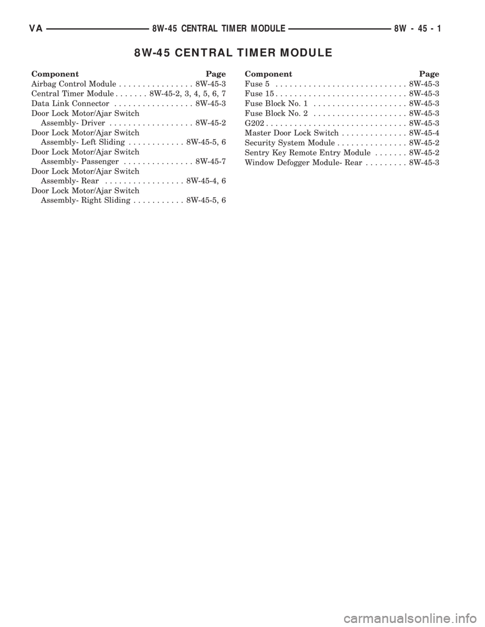
8W-45 CENTRAL TIMER MODULE
Component Page
Airbag Control Module................ 8W-45-3
Central Timer Module....... 8W-45-2, 3, 4, 5, 6, 7
Data Link Connector................. 8W-45-3
Door Lock Motor/Ajar Switch
Assembly- Driver.................. 8W-45-2
Door Lock Motor/Ajar Switch
Assembly- Left Sliding............ 8W-45-5, 6
Door Lock Motor/Ajar Switch
Assembly- Passenger............... 8W-45-7
Door Lock Motor/Ajar Switch
Assembly- Rear................. 8W-45-4, 6
Door Lock Motor/Ajar Switch
Assembly- Right Sliding........... 8W-45-5, 6Component Page
Fuse 5............................ 8W-45-3
Fuse 15............................ 8W-45-3
Fuse Block No. 1.................... 8W-45-3
Fuse Block No. 2.................... 8W-45-3
G202.............................. 8W-45-3
Master Door Lock Switch.............. 8W-45-4
Security System Module............... 8W-45-2
Sentry Key Remote Entry Module....... 8W-45-2
Window Defogger Module- Rear......... 8W-45-3
VA8W-45 CENTRAL TIMER MODULE 8W - 45 - 1