2005 MERCEDES-BENZ SPRINTER sliding
[x] Cancel search: slidingPage 1083 of 1232
(7) Loosen center roller bolt and adjust the front
and rear gaps.
(8) Check rear ridge pattern alignment and
tighten bolt to 45 N´m (33 ft. lbs.).
Flush Adjustment
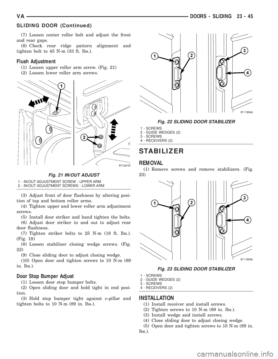
(1) Loosen upper roller arm screw. (Fig. 21)
(2) Loosen lower roller arm screws.
(3) Adjust front of door flushness by altering posi-
tion of top and bottom roller arms.
(4) Tighten upper and lower roller arm adjustment
screws.
(5) Install door striker and hand tighten the bolts.
(6) Adjust door striker in and out to adjust rear
door flushness.
(7) Tighten striker bolts to 25 N´m (18 ft. lbs.).
(Fig. 18)
(8) Loosen stabilizer closing wedge screws. (Fig.
22)
(9) Close sliding door to adjust closing wedge.
(10) Open door and tighten screws to 10 N´m (89
in. lbs.).
Door Stop Bumper Adjust
(1) Loosen door stop bumper bolts.
(2) Open sliding door and hold tight in end posi-
tion.
(3) Hold stop bumper tight against c-pillar and
tighten bolts to 10 N´m (89 in. lbs.).
STABILIZER
REMOVAL
(1) Remove screws and remove stabilizers. (Fig.
23)
INSTALLATION
(1) Install receiver and install screws.
(2) Tighten screws to 10 N´m (89 in. lbs.).
(3) Install wedge and install screws.
(4) Close sliding door to adjust closing wedge.
(5) Open door and tighten screws to 10 N´m (89 in.
lbs.).
Fig. 21 IN/OUT ADJUST
1 - IN/OUT ADJUSTMENT SCREW - UPPER ARM
2 - IN/OUT ADJUSTMENT SCREWS - LOWER ARM
Fig. 22 SLIDING DOOR STABILIZER
1 - SCREWS
2 - GUIDE WEDGES (2)
3 - SCREWS
4 - RECEIVERS (2)
Fig. 23 SLIDING DOOR STABILIZER
1 - SCREWS
2 - GUIDE WEDGES (2)
3 - SCREWS
4 - RECEIVERS (2)
VADOORS - SLIDING 23 - 45
SLIDING DOOR (Continued)
Page 1084 of 1232
TRIM PANEL
REMOVAL
Upper
(1) Remove rivets and remove panel.
Lower
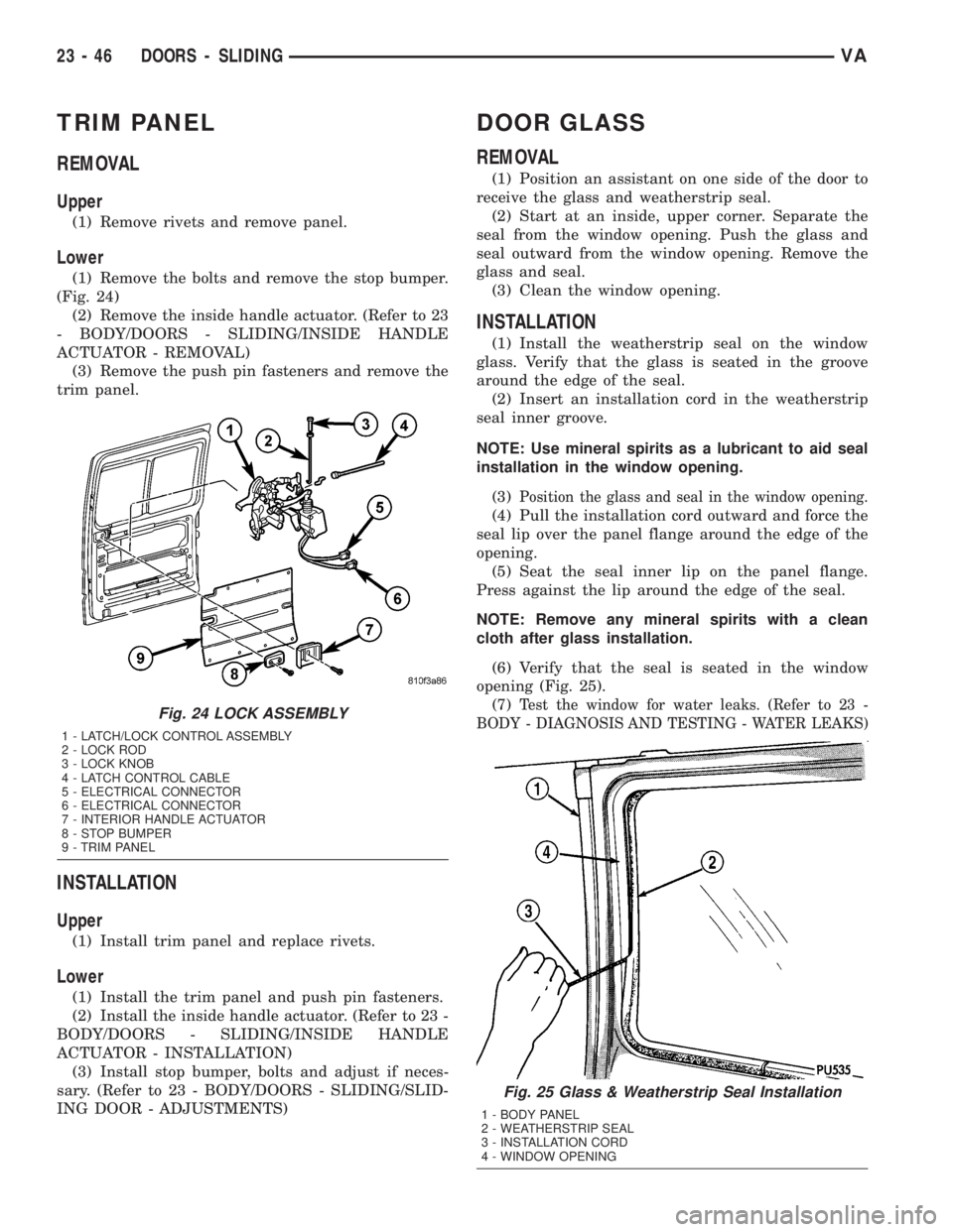
(1) Remove the bolts and remove the stop bumper.
(Fig. 24)
(2) Remove the inside handle actuator. (Refer to 23
- BODY/DOORS - SLIDING/INSIDE HANDLE
ACTUATOR - REMOVAL)
(3) Remove the push pin fasteners and remove the
trim panel.
INSTALLATION
Upper
(1) Install trim panel and replace rivets.
Lower
(1) Install the trim panel and push pin fasteners.
(2) Install the inside handle actuator. (Refer to 23 -
BODY/DOORS - SLIDING/INSIDE HANDLE
ACTUATOR - INSTALLATION)
(3) Install stop bumper, bolts and adjust if neces-
sary. (Refer to 23 - BODY/DOORS - SLIDING/SLID-
ING DOOR - ADJUSTMENTS)
DOOR GLASS
REMOVAL
(1) Position an assistant on one side of the door to
receive the glass and weatherstrip seal.
(2) Start at an inside, upper corner. Separate the
seal from the window opening. Push the glass and
seal outward from the window opening. Remove the
glass and seal.
(3) Clean the window opening.
INSTALLATION
(1) Install the weatherstrip seal on the window
glass. Verify that the glass is seated in the groove
around the edge of the seal.
(2) Insert an installation cord in the weatherstrip
seal inner groove.
NOTE: Use mineral spirits as a lubricant to aid seal
installation in the window opening.
(3)
Position the glass and seal in the window opening.
(4) Pull the installation cord outward and force the
seal lip over the panel flange around the edge of the
opening.
(5) Seat the seal inner lip on the panel flange.
Press against the lip around the edge of the seal.
NOTE: Remove any mineral spirits with a clean
cloth after glass installation.
(6) Verify that the seal is seated in the window
opening (Fig. 25).
(7)
Test the window for water leaks. (Refer to 23 -
BODY - DIAGNOSIS AND TESTING - WATER LEAKS)
Fig. 25 Glass & Weatherstrip Seal Installation
1 - BODY PANEL
2 - WEATHERSTRIP SEAL
3 - INSTALLATION CORD
4 - WINDOW OPENING
Fig. 24 LOCK ASSEMBLY
1 - LATCH/LOCK CONTROL ASSEMBLY
2 - LOCK ROD
3 - LOCK KNOB
4 - LATCH CONTROL CABLE
5 - ELECTRICAL CONNECTOR
6 - ELECTRICAL CONNECTOR
7 - INTERIOR HANDLE ACTUATOR
8 - STOP BUMPER
9 - TRIM PANEL
23 - 46 DOORS - SLIDINGVA
Page 1111 of 1232
INSTALLATION
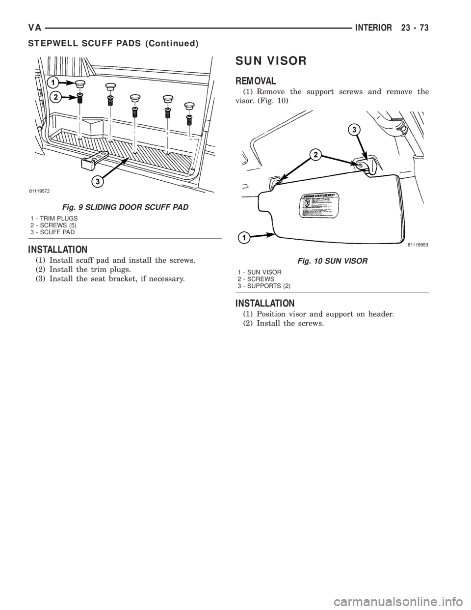
(1) Install scuff pad and install the screws.
(2) Install the trim plugs.
(3) Install the seat bracket, if necessary.
SUN VISOR
REMOVAL
(1) Remove the support screws and remove the
visor. (Fig. 10)
INSTALLATION
(1) Position visor and support on header.
(2) Install the screws.
Fig. 9 SLIDING DOOR SCUFF PAD
1 - TRIM PLUGS
2 - SCREWS (5)
3 - SCUFF PAD
Fig. 10 SUN VISOR
1 - SUN VISOR
2 - SCREWS
3 - SUPPORTS (2)
VAINTERIOR 23 - 73
STEPWELL SCUFF PADS (Continued)
Page 1126 of 1232
BODY STRUCTURE
TABLE OF CONTENTS
page page
GAP AND FLUSH
SPECIFICATIONS.......................88OPENING DIMENSIONS
SPECIFICATIONS.......................90
GAP AND FLUSH
SPECIFICATIONS
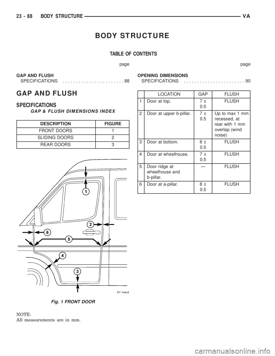
GAP & FLUSH DIMENSIONS INDEX
DESCRIPTION FIGURE
FRONT DOORS 1
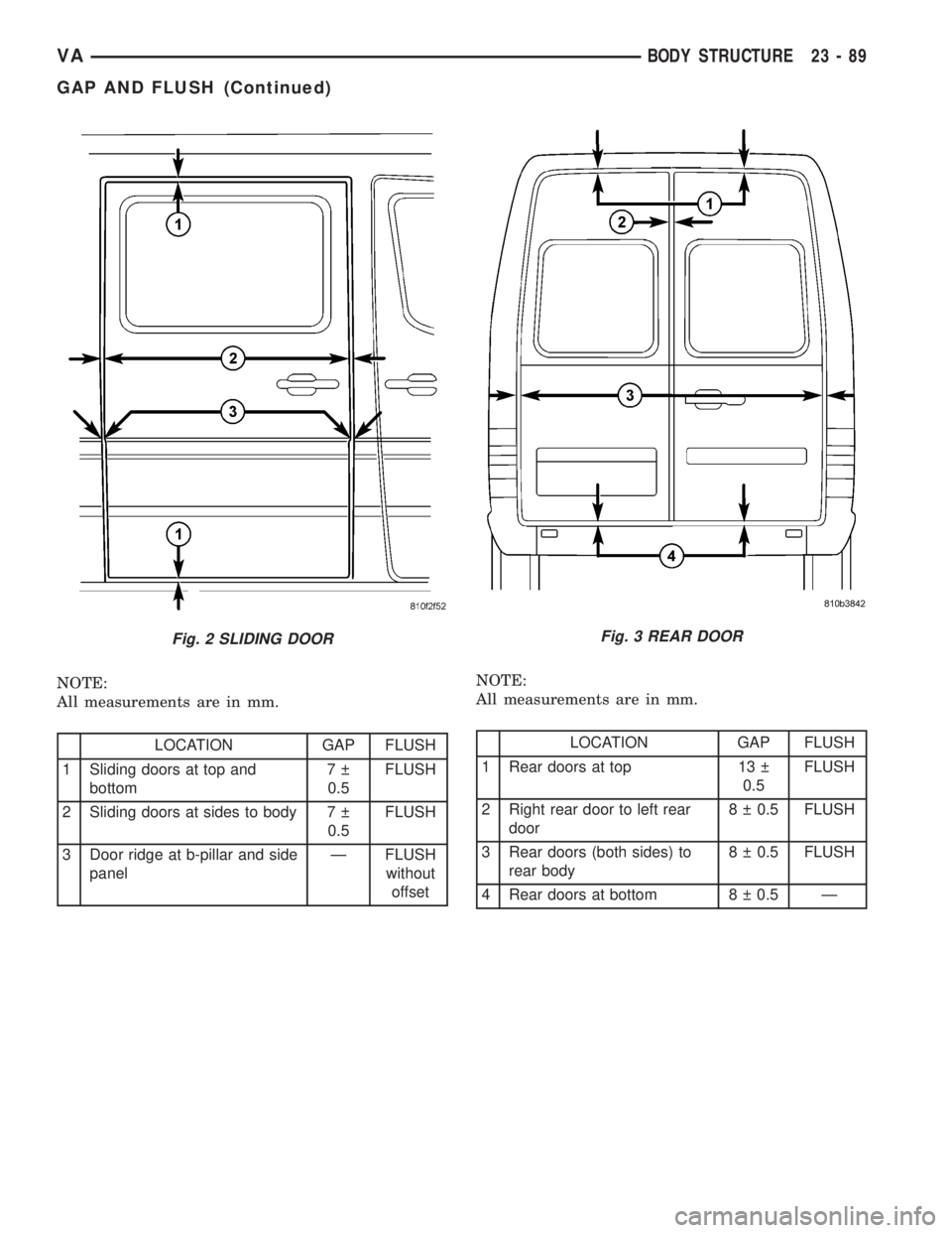
SLIDING DOORS 2
REAR DOORS 3
NOTE:
All measurements are in mm.
LOCATION GAP FLUSH
1 Door at top. 7
0.5FLUSH
2 Door at upper b-pillar. 7
0.5Up to max 1 mm
recessed, at
rear with 1 mm
overlap (wind
noise)
3 Door at bottom. 8
0.5FLUSH
4 Door at wheelhouse. 7
0.5FLUSH
5 Door ridge at
wheelhouse and
b-pillar.Ð FLUSH
6 Door at a-pillar. 8
0.5FLUSH
Fig. 1 FRONT DOOR
23 - 88 BODY STRUCTUREVA
Page 1127 of 1232
NOTE:
All measurements are in mm.
LOCATION GAP FLUSH
1 Sliding doors at top and
bottom7
0.5FLUSH
2 Sliding doors at sides to body 7
0.5FLUSH
3 Door ridge at b-pillar and side
panelÐ FLUSH
without
offsetNOTE:
All measurements are in mm.LOCATION GAP FLUSH
1 Rear doors at top 13
0.5FLUSH
2 Right rear door to left rear
door8 0.5 FLUSH
3 Rear doors (both sides) to
rear body8 0.5 FLUSH
4 Rear doors at bottom 8 0.5 Ð
Fig. 2 SLIDING DOORFig. 3 REAR DOOR
VABODY STRUCTURE 23 - 89
GAP AND FLUSH (Continued)
Page 1144 of 1232
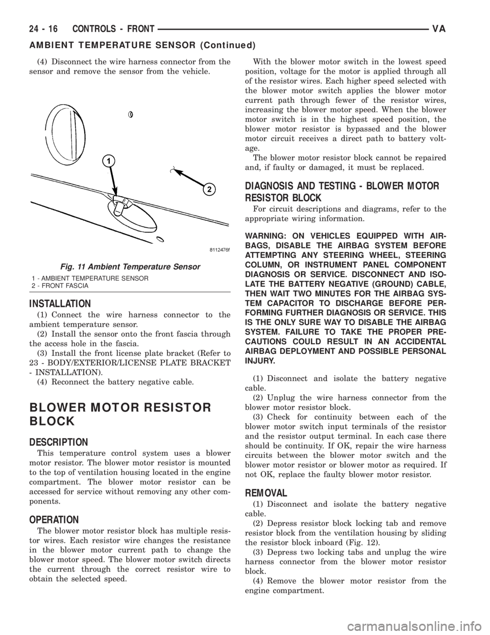
(4) Disconnect the wire harness connector from the
sensor and remove the sensor from the vehicle.
INSTALLATION
(1) Connect the wire harness connector to the
ambient temperature sensor.
(2) Install the sensor onto the front fascia through
the access hole in the fascia.
(3) Install the front license plate bracket (Refer to
23 - BODY/EXTERIOR/LICENSE PLATE BRACKET
- INSTALLATION).
(4) Reconnect the battery negative cable.
BLOWER MOTOR RESISTOR
BLOCK
DESCRIPTION
This temperature control system uses a blower
motor resistor. The blower motor resistor is mounted
to the top of ventilation housing located in the engine
compartment. The blower motor resistor can be
accessed for service without removing any other com-
ponents.
OPERATION
The blower motor resistor block has multiple resis-
tor wires. Each resistor wire changes the resistance
in the blower motor current path to change the
blower motor speed. The blower motor switch directs
the current through the correct resistor wire to
obtain the selected speed.With the blower motor switch in the lowest speed
position, voltage for the motor is applied through all
of the resistor wires. Each higher speed selected with
the blower motor switch applies the blower motor
current path through fewer of the resistor wires,
increasing the blower motor speed. When the blower
motor switch is in the highest speed position, the
blower motor resistor is bypassed and the blower
motor circuit receives a direct path to battery volt-
age.
The blower motor resistor block cannot be repaired
and, if faulty or damaged, it must be replaced.
DIAGNOSIS AND TESTING - BLOWER MOTOR
RESISTOR BLOCK
For circuit descriptions and diagrams, refer to the
appropriate wiring information.
WARNING: ON VEHICLES EQUIPPED WITH AIR-
BAGS, DISABLE THE AIRBAG SYSTEM BEFORE
ATTEMPTING ANY STEERING WHEEL, STEERING
COLUMN, OR INSTRUMENT PANEL COMPONENT
DIAGNOSIS OR SERVICE. DISCONNECT AND ISO-
LATE THE BATTERY NEGATIVE (GROUND) CABLE,
THEN WAIT TWO MINUTES FOR THE AIRBAG SYS-
TEM CAPACITOR TO DISCHARGE BEFORE PER-
FORMING FURTHER DIAGNOSIS OR SERVICE. THIS
IS THE ONLY SURE WAY TO DISABLE THE AIRBAG
SYSTEM. FAILURE TO TAKE THE PROPER PRE-
CAUTIONS COULD RESULT IN AN ACCIDENTAL
AIRBAG DEPLOYMENT AND POSSIBLE PERSONAL
INJURY.
(1) Disconnect and isolate the battery negative
cable.
(2) Unplug the wire harness connector from the
blower motor resistor block.
(3) Check for continuity between each of the
blower motor switch input terminals of the resistor
and the resistor output terminal. In each case there
should be continuity. If OK, repair the wire harness
circuits between the blower motor switch and the
blower motor resistor or blower motor as required. If
not OK, replace the faulty blower motor resistor.
REMOVAL
(1) Disconnect and isolate the battery negative
cable.
(2) Depress resistor block locking tab and remove
resistor block from the ventilation housing by sliding
the resistor block inboard (Fig. 12).
(3) Depress two locking tabs and unplug the wire
harness connector from the blower motor resistor
block.
(4) Remove the blower motor resistor from the
engine compartment.
Fig. 11 Ambient Temperature Sensor
1 - AMBIENT TEMPERATURE SENSOR
2 - FRONT FASCIA
24 - 16 CONTROLS - FRONTVA
AMBIENT TEMPERATURE SENSOR (Continued)
Page 1215 of 1232
COVER - REMOVAL, TIMING CHAIN.......9-59
COVER - REMOVAL, TOP..............23-64
COVER - TRAY - INSTALLATION, TOP.....23-64
COVER - TRAY - REMOVAL, TOP........23-63
COVER(S) - INSTALLATION, CYLINDER
HEAD...............................9-30
COVER(S) - REMOVAL, CYLINDER HEAD . . . 9-30
COWL TRIM - INSTALLATION...........23-70
COWL TRIM - REMOVAL...............23-70
CRADLE CROSSMEMBER -
INSTALLATION, ENGINE................13-8
CRADLE CROSSMEMBER - REMOVAL,
ENGINE.............................13-6
CRANKSHAFT - INSTALLATION...........9-36
CRANKSHAFT - REMOVAL..............9-35
CRANKSHAFT AND BLOCK JOURNALS -
STANDARD PROCEDURE, MEASURE......9-35
CRANKSHAFT OIL SEAL - FRONT -
INSTALLATION........................9-38
CRANKSHAFT OIL SEAL - FRONT -
REMOVAL...........................9-38
CRANKSHAFT OIL SEAL - REAR -
INSTALLATION........................9-37
CRANKSHAFT OIL SEAL - REAR -
REMOVAL...........................9-37
CRANKSHAFT POSITION SENSOR -
DESCRIPTION.......................14-20
CRANKSHAFT POSITION SENSOR -
INSTALLATION.......................14-20
CRANKSHAFT POSITION SENSOR -
OPERATION..........................14-20
CRANKSHAFT POSITION SENSOR -
REMOVAL..........................14-20
CROSSMEMBER - INSTALLATION,
ENGINE CRADLE......................13-8
CROSSMEMBER - INSTALLATION,
RADIATOR..........................23-48
CROSSMEMBER - REMOVAL, ENGINE
CRADLE.............................13-6
CROSSMEMBER - REMOVAL, RADIATOR . . 23-47
CROSSMEMBER - TRANSMISSION -
INSTALLATION, REAR..................13-9
CROSSMEMBER - TRANSMISSION -
REMOVAL, REAR......................13-9
CUP HOLDER - INSTALLATION..........23-56
CUP HOLDER - REMOVAL..............23-55
CUSHION - FRONT - INSTALLATION,
SEAT ..............................23-78
CUSHION - FRONT - REMOVAL, SEAT....23-78
CUSHION/COVER - REAR -
INSTALLATION, SEAT.................23-80
CUSHION/COVER - REAR -
INSTALLATION, SEAT BACK............23-80
CUSHION/COVER - REAR - REMOVAL,
SEAT
..............................23-80
CUSHION/COVER - REAR - REMOVAL,
SEAT BACK
.........................23-80
CYLINDER - INSTALLATION, KEY/LOCK
....19-7
CYLINDER - INSTALLATION, LOCK
.......23-18
CYLINDER - INSTALLATION, MASTER
.....5-18
CYLINDER - REMOVAL, KEY/LOCK
........19-6
CYLINDER - REMOVAL, LOCK
...........23-18
CYLINDER - REMOVAL, MASTER
.........5-17
CYLINDER BLEEDING - STANDARD
PROCEDURE, MASTER
.................5-17
CYLINDER BORES - STANDARD
PROCEDURE, MEASURING
..............9-34
CYLINDER HEAD - INSTALLATION
........9-25
CYLINDER HEAD - REMOVAL
............9-22
CYLINDER HEAD BOLT INSPECTION -
STANDARD PROCEDURE
................9-21
CYLINDER HEAD COVER(S) -
INSTALLATION
........................9-30
CYLINDER HEAD COVER(S) - REMOVAL
. . . 9-30
CYLINDER HEAD FRONT COVER -
INSTALLATION
........................9-26
CYLINDER HEAD FRONT COVER -
REMOVAL
...........................9-23
CYLINDER HEAD GUIDE RAIL -
INSTALLATION
........................9-26
CYLINDER HEAD GUIDE RAIL -
REMOVAL
...........................9-24
CYLINDER HEAD SURFACE - STANDARD
PROCEDURE, MEASURE
................9-21
CYLINDER LEAK DOWN TEST -
STANDARD PROCEDURE
.................9-3CYLINDER PRESSURE LOSS -
STANDARD PROCEDURE,
DETERMINING.........................9-4
CYLINDER/POWER BOOSTER -
DIAGNOSIS AND TESTING, MASTER......5-16
DAMPER - INSTALLATION, VIBRATION.....9-48
DAMPER - REMOVAL, VIBRATION........9-47
DAYTIME RUNNING LAMP RELAY -
INSTALLATION........................8L-9
DAYTIME RUNNING LAMP RELAY -
REMOVAL...........................8L-9
DCHA - DIAGNOSIS AND TESTING,
DIESEL SUPPLEMENTAL HEATER........24-72
DECOUPLER - DIAGNOSIS AND
TESTING, GENERATOR................8F-19
DECOUPLER PULLEY - DESCRIPTION,
GENERATOR........................8F-19
DECOUPLER PULLEY - INSTALLATION,
GENERATOR........................8F-21
DECOUPLER PULLEY - OPERATION,
GENERATOR........................8F-19
DECOUPLER PULLEY - REMOVAL,
GENERATOR........................8F-20
DEFROSTER DUCTS - INSTALLATION.....24-33
DEFROSTER DUCTS - REMOVAL.........24-33
DELAY RELAY - INSTALLATION, TIME....8L-33
DELAY RELAY - REMOVAL, TIME........8L-32
DEPLOYMENT - STANDARD
PROCEDURE, SERVICE AFTER A
SUPPLEMENTAL RESTRAINT............8O-6
DETERMINING CYLINDER PRESSURE
LOSS - STANDARD PROCEDURE..........9-4
DEVICES - STANDARD PROCEDURE,
ELECTROSTATIC DISCHARGE (ESD)
SENSITIVE........................8W-01-7
DIAGRAMS - DESCRIPTION, HOW TO
USE WIRING......................8W-01-1
DIAGRAMS, DIAGNOSIS AND TESTING -
SCHEMATICS........................21-47
DIESEL - DESCRIPTION, 2.7L............11-1
DIESEL - SPECIFICATIONS, STARTER
MOTOR............................8F-29
DIESEL - TORQUE, 2.7L...............8F-17
DIESEL - TORQUE, STARTER...........8F-29
DIESEL ENGINE - DESCRIPTION, FUEL
REQUIREMENTS.......................0-1
DIESEL ENGINE - DIAGNOSIS AND
TESTING............................11-2
DIESEL ENGINES - DESCRIPTION,
ENGINE OIL...........................0-3
DIESEL SUPPLEMENTAL HEATER - DCHA
- DIAGNOSIS AND TESTING............24-72
DIMENSIONS - SPECIFICATIONS, FRAME . . . 13-4
DIMENSIONS - SPECIFICATIONS,
OPENING...........................23-90
DIODE - INSTALLATION.............8W-01-9
DIODE - REMOVAL.................8W-01-9
DISCHARGE (ESD) SENSITIVE DEVICES -
STANDARD PROCEDURE,
ELECTROSTATIC...................8W-01-7
DISCHARGE LINE - INSTALLATION, A/C . . . 24-54
DISCHARGE LINE - REMOVAL, A/C.......24-53
DISCONNECTING AND CONNECTING
FUEL LINES - STANDARD PROCEDURE....14-2
DISTRIBUTION - DESCRIPTION,
POWER..........................8W-97-1
DISTRIBUTION - OPERATION, POWER . . 8W-97-1
DISTRIBUTION CENTER - DESCRIPTION,
POWER..........................8W-97-3
DISTRIBUTION CENTER - OPERATION,
POWER..........................8W-97-3
DISTRIBUTION DUCTS - INSTALLATION,
FLOOR.............................24-34
DISTRIBUTION DUCTS - REMOVAL,
FLOOR.............................24-33
DOME LAMP/INTRUSION SENSOR -
INSTALLATION.......................8L-31
DOME LAMP/INTRUSION SENSOR -
REMOVAL..........................8L-31
DOME LAMP/INTRUSION SENSOR BULB
- INSTALLATION
.....................8L-30
DOME LAMP/INTRUSION SENSOR BULB
- REMOVAL
.........................8L-30
DOME/READING LAMP BULB -
INSTALLATION
.......................8L-29
DOME/READING LAMP BULB - REMOVAL
. 8L-29
DOME/READING LAMP UNIT -
INSTALLATION
.......................8L-30DOME/READING LAMP UNIT - REMOVAL . . 8L-30
DOOR - ASSEMBLY...................23-28
DOOR - ASSEMBLY, SLIDING...........23-43
DOOR - DISASSEMBLY................23-26
DOOR - DISASSEMBLY, SLIDING........23-42
DOOR - INSTALLATION...........23-14,23-30
DOOR - INSTALLATION, FUEL FILL.......23-47
DOOR - INSTALLATION, SLIDING........23-44
DOOR - REMOVAL...............23-14,23-25
DOOR - REMOVAL, FUEL FILL..........23-47
DOOR - REMOVAL, SLIDING............23-41
DOOR ACTUATOR - DESCRIPTION,
RECIRCULATION.....................24-20
DOOR ACTUATOR - INSTALLATION,
RECIRCULATION.....................24-21
DOOR ACTUATOR - OPERATION,
RECIRCULATION.....................24-20
DOOR ACTUATOR - REMOVAL,
RECIRCULATION.....................24-21
DOOR CABLES - INSTALLATION, MODE . . . 24-19
DOOR CABLES - REMOVAL, MODE.......24-19
DOOR GLASS - INSTALLATION....23-15,23-31,
23-46
DOOR GLASS - REMOVAL . . . 23-15,23-31,23-46
DOOR INNER BELT WEATHERSTRIP -
INSTALLATION, FRONT................23-87
DOOR INNER BELT WEATHERSTRIP -
REMOVAL, FRONT....................23-87
DOOR JAMB SWITCH - INSTALLATION.....8L-31
DOOR JAMB SWITCH - REMOVAL.......8L-31
DOOR LOCK MOTOR - INSTALLATION.....8N-1
DOOR LOCK MOTOR - REMOVAL.........8N-1
DOOR OPENING SEALS - INSTALLATION . . 23-87
DOOR OPENING SEALS - REMOVAL......23-87
DOOR OUTER BELT WEATHERSTRIP -
INSTALLATION, FRONT................23-87
DOOR OUTER BELT WEATHERSTRIP -
REMOVAL, FRONT....................23-87
DOSING PUMP - DESCRIPTION, FUEL....24-74
DOSING PUMP - INSTALLATION, FUEL....24-74
DOSING PUMP - OPERATION, FUEL......24-74
DOSING PUMP - REMOVAL, FUEL.......24-74
DOUBLE INVERTED FLARING -
STANDARD PROCEDURE.................5-8
D-PILLAR TRIM - INSTALLATION........23-70
D-PILLAR TRIM - REMOVAL............23-70
DRAIN AND FILL - STANDARD
PROCEDURE.........................3-11
DRAINING COOLING SYSTEM -
STANDARD PROCEDURE................7-12
DRAINING WATER FROM FUEL FILTER -
STANDARD PROCEDURES...............14-2
DRAW TEST - STANDARD PROCEDURE,
IGNITION-OFF.......................8F-10
DRIVE BELT - DIAGNOSIS AND TESTING,
ACCESSORY..........................7-5
DRIVE BELTS - INSTALLATION............7-8
DRIVE BELTS - REMOVAL................7-8
DRIVE VISCOUS CLUTCH -
INSTALLATION, FAN...................7-16
DRIVE VISCOUS CLUTCH - REMOVAL,
FAN ................................7-16
DRIVER AIRBAG - DESCRIPTION........8O-16
DRIVER AIRBAG - INSTALLATION.......8O-18
DRIVER AIRBAG - OPERATION..........8O-17
DRIVER AIRBAG - REMOVAL...........8O-17
DRIVER HEATED SEAT SWITCH -
DESCRIPTION........................8G-2
DRIVER HEATED SEAT SWITCH -
DIAGNOSIS AND TESTING..............8G-2
DRIVER HEATED SEAT SWITCH -
INSTALLATION.......................8G-3
DRIVER HEATED SEAT SWITCH -
OPERATION..........................8G-2
DRIVER HEATED SEAT SWITCH -
REMOVAL...........................8G-3
DRIVING CLUTCH K1 - ASSEMBLY.......21-75
DRIVING CLUTCH K1 - DISASSEMBLY....21-74
DRIVING CLUTCH K2 - ASSEMBLY.......21-78
DRIVING CLUTCH K2 - DISASSEMBLY....21-76
DRIVING CLUTCH K3 - ASSEMBLY.......21-80
DRIVING CLUTCH K3 - DISASSEMBLY
....21-80
DRIVING CLUTCHES - DESCRIPTION
.....21-72
DRIVING CLUTCHES - OPERATION
.......21-72
DROP - STANDARD PROCEDURE,
TESTING FOR A VOLTAGE
............8W-01-8
DRUM IN HAT BRAKE - CLEANING,
REAR
...............................5-27
VAINDEX 5
Description Group-Page Description Group-Page Description Group-Page
Page 1225 of 1232
SENDING UNIT / SENSOR -
DESCRIPTION, FUEL LEVEL............14-15
SENDING UNIT / SENSOR -
INSTALLATION, FUEL LEVEL............14-15
SENDING UNIT / SENSOR - REMOVAL,
FUEL LEVEL.........................14-15
SENSITIVE DEVICES - STANDARD
PROCEDURE, ELECTROSTATIC
DISCHARGE (ESD).................8W-01-7
SENSOR - DESCRIPTION, ACCELERATOR
PEDAL POSITION....................14-17
SENSOR - DESCRIPTION, AIR OUTLET
TEMPERATURE......................24-14
SENSOR - DESCRIPTION, AMBIENT
TEMPERATURE......................24-15
SENSOR - DESCRIPTION, BOOST
PRESSURE.........................14-17
SENSOR - DESCRIPTION, CAMSHAFT
POSITION..........................14-19
SENSOR - DESCRIPTION, CRANKSHAFT
POSITION..........................14-20
SENSOR - DESCRIPTION, ENGINE
COOLANT TEMP......................7-14
SENSOR - DESCRIPTION, EVAPORATOR
TEMPERATURE.................24-17,24-25
SENSOR - DESCRIPTION, FUEL LEVEL
SENDING UNIT......................14-15
SENSOR - DESCRIPTION, FUEL
TEMPERATURE......................14-29
SENSOR - DESCRIPTION, HEATED SEAT . . . 8G-4
SENSOR - DESCRIPTION, IN-CAR
TEMPERATURE......................24-19
SENSOR - DESCRIPTION, INLET AIR
TEMPERATURE........................14-29
SENSOR - DESCRIPTION, MANIFOLD AIR
FLOW (MAF)........................14-30
SENSOR - DESCRIPTION, OIL
TEMPERATURE.......................9-56
SENSOR - DESCRIPTION, TEMPERATURE . 24-30
SENSOR - DESCRIPTION,
TRANSMISSION TEMPERATURE........21-140
SENSOR - DESCRIPTION, WATER IN
FUEL..............................14-16
SENSOR - DIAGNOSIS AND TESTING,
BOOST PRESSURE...................14-18
SENSOR - DIAGNOSIS AND TESTING,
EVAPORATOR TEMPERATURE...........24-26
SENSOR - DIAGNOSIS AND TESTING,
HEATED SEAT ........................8G-4
SENSOR - DIAGNOSIS AND TESTING,
IN-CAR TEMPERATURE................24-19
SENSOR - DIAGNOSIS AND TESTING,
TEMPERATURE......................24-30
SENSOR - INSTALLATION, AIR OUTLET
TEMPERATURE......................24-15
SENSOR - INSTALLATION, AMBIENT
TEMPERATURE......................24-16
SENSOR - INSTALLATION, BOOST
PRESSURE.........................14-18
SENSOR - INSTALLATION, CAMSHAFT
POSITION..........................14-19
SENSOR - INSTALLATION, COOLANT
LEVEL..............................7-13
SENSOR - INSTALLATION, CRANKSHAFT
POSITION..........................14-20
SENSOR - INSTALLATION, DOME
LAMP/INTRUSION....................8L-31
SENSOR - INSTALLATION, ENGINE
COOLANT TEMP......................7-15
SENSOR - INSTALLATION, EVAPORATOR
TEMPERATURE.................24-18,24-26
SENSOR - INSTALLATION, FRONT
WHEEL SPEED........................5-30
SENSOR - INSTALLATION, FUEL LEVEL
SENDING UNIT......................14-15
SENSOR - INSTALLATION, FUEL
TEMPERATURE......................14-29
SENSOR - INSTALLATION, INLET AIR
TEMPERATURE......................14-30
SENSOR - INSTALLATION, INTRUSION
....8Q-2
SENSOR - INSTALLATION, MANIFOLD
AIR FLOW (MAF)
.....................14-31
SENSOR - INSTALLATION, OIL
TEMPERATURE
.......................9-57
SENSOR - INSTALLATION, REAR WHEEL
SPEED
..............................5-31
SENSOR - INSTALLATION,
TEMPERATURE
......................24-30SENSOR - OPERATION, AIR OUTLET
TEMPERATURE......................24-15
SENSOR - OPERATION, AMBIENT
TEMPERATURE......................24-15
SENSOR - OPERATION, BOOST
PRESSURE.........................14-18
SENSOR - OPERATION, CAMSHAFT
POSITION..........................14-19
SENSOR - OPERATION, CRANKSHAFT
POSITION..........................14-20
SENSOR - OPERATION, EVAPORATOR
TEMPERATURE.................24-18,24-26
SENSOR - OPERATION, FUEL
TEMPERATURE......................14-29
SENSOR - OPERATION, IN-CAR
TEMPERATURE......................24-19
SENSOR - OPERATION, INLET AIR
TEMPERATURE......................14-29
SENSOR - OPERATION, MANIFOLD AIR
FLOW (MAF)........................14-30
SENSOR - OPERATION, OIL
TEMPERATURE.......................9-56
SENSOR - OPERATION, TEMPERATURE . . . 24-30
SENSOR - OPERATION, TRANSMISSION
TEMPERATURE.....................21-141
SENSOR - OPERATION, WATER IN FUEL . . 14-16
SENSOR - REMOVAL, AIR OUTLET
TEMPERATURE......................24-15
SENSOR - REMOVAL, AMBIENT
TEMPERATURE......................24-15
SENSOR - REMOVAL, BOOST PRESSURE . . 14-18
SENSOR - REMOVAL, CAMSHAFT
POSITION............................14-19
SENSOR - REMOVAL, COOLANT LEVEL....7-13
SENSOR - REMOVAL, CRANKSHAFT
POSITION..........................14-20
SENSOR - REMOVAL, DOME LAMP/
INTRUSION.........................8L-31
SENSOR - REMOVAL, ENGINE COOLANT
TEMP...............................7-14
SENSOR - REMOVAL, EVAPORATOR
TEMPERATURE.................24-18,24-26
SENSOR - REMOVAL, FRONT WHEEL
SPEED..............................5-30
SENSOR - REMOVAL, FUEL LEVEL
SENDING UNIT......................14-15
SENSOR - REMOVAL, FUEL
TEMPERATURE......................14-29
SENSOR - REMOVAL, IN-CAR
TEMPERATURE......................24-19
SENSOR - REMOVAL, INLET AIR
TEMPERATURE......................14-30
SENSOR - REMOVAL, INTRUSION........8Q-2
SENSOR - REMOVAL, MANIFOLD AIR
FLOW (MAF)........................14-31
SENSOR - REMOVAL, OIL
TEMPERATURE.......................9-57
SENSOR - REMOVAL, REAR WHEEL
SPEED..............................5-30
SENSOR - REMOVAL, TEMPERATURE....24-30
SENSOR BULB - INSTALLATION, DOME
LAMP/INTRUSION....................8L-30
SENSOR BULB - REMOVAL, DOME
LAMP/INTRUSION....................8L-30
SENSORS - DESCRIPTION, INPUT SPEED . 21-119
SENSORS - OPERATION, INPUT SPEED . . 21-119
SENTRY KEY REMOTE ENTRY MODULE -
DESCRIPTION........................8Q-2
SENTRY KEY REMOTE ENTRY MODULE -
INSTALLATION.......................8Q-4
SENTRY KEY REMOTE ENTRY MODULE -
OPERATION..........................8Q-3
SENTRY KEY REMOTE ENTRY MODULE -
REMOVAL...........................8Q-3
SEPARATOR - INSTALLATION, OIL........9-50
SEPARATOR - REMOVAL, OIL............9-50
SERVO - DESCRIPTION.................8P-3
SEVERAL LOADS - STANDARD
PROCEDURE, TESTING FOR A SHORT
TO GROUND ON FUSES POWERING . . . 8W-01-8
SHACKLE - INSTALLATION, SPRING.......2-15
SHACKLE - REMOVAL, SPRING..........2-15
SHAFT - DIAGNOSIS AND TESTING,
PROPELLER
...........................3-1
SHAFT - INSTALLATION, INTERMEDIATE
. . . 19-5
SHAFT - INSTALLATION, PROPELLER
.......3-6
SHAFT - REMOVAL, INTERMEDIATE
.......19-5
SHAFT - REMOVAL, PROPELLER
..........3-6SHAFT - SPECIAL TOOLS, PROPELLER.....3-5
SHAFT - SPECIFICATIONS, PROPELLER.....3-5
SHAFT - STANDARD PROCEDURE,
PROPELLER...........................3-3
SHAFT BEARING - INSTALLATION,
OUTPUT...........................21-122
SHAFT BEARING - REMOVAL, OUTPUT . . . 21-122
SHAFT SEAL - INSTALLATION, OUTPUT . . 21-125
SHAFT SEAL - REMOVAL, OUTPUT......21-125
SHAFTS - DUAL REAR WHEELS -
INSTALLATION, AXLE..................3-19
SHAFTS - DUAL REAR WHEELS -
REMOVAL, AXLE......................3-19
SHAFTS - INSTALLATION, AXLE..........3-15
SHAFTS - REMOVAL, AXLE..............3-15
SHIELD - INSTALLATION, REAR SEAT
BACK..............................23-79
SHIELD - REMOVAL, REAR SEAT BACK . . . 23-79
SHIFT MECHANISM - DESCRIPTION.....21-133
SHIFT MECHANISM - INSTALLATION....21-135
SHIFT MECHANISM - OPERATION......21-133
SHIFT MECHANISM - REMOVAL........21-134
SHOCK - DIAGNOSIS AND TESTING.......2-13
SHOCK - DIAGNOSIS AND TESTING,
SPRING.............................2-11
SHOCK - INSTALLATION................2-13
SHOCK - REMOVAL....................2-13
SHORT TO GROUND - STANDARD
PROCEDURE, TESTING FOR A..........8W-01-8
SHORT TO GROUND ON FUSES
POWERING SEVERAL LOADS -
STANDARD PROCEDURE, TESTING
FOR A ...........................8W-01-8
SHUTOFF SOL - DESCRIPTION, HI
PRESSURE FUEL.....................14-16
SHUTOFF SOL - OPERATION, HI
PRESSURE FUEL.....................14-16
SIDE MARKER LAMP BULB -
INSTALLATION, REAR.................8L-21
SIDE MARKER LAMP BULB - REMOVAL,
REAR..............................8L-21
SIDE VIEW MIRROR - GLASS -
INSTALLATION.......................23-49
SIDE VIEW MIRROR - GLASS -
REMOVAL..........................23-49
SIDE VIEW MIRROR - INSTALLATION.....23-48
SIDE VIEW MIRROR - REMOVAL........23-48
SIGNAL INDICATOR - DESCRIPTION,
TURN..............................8J-25
SIGNAL INDICATOR - OPERATION, TURN . . 8J-25
SIGNAL RELAY - INSTALLATION, TURN . . . 8L-24
SIGNAL RELAY - REMOVAL, TURN.......8L-24
SIREN - INSTALLATION................8Q-4
SIREN - REMOVAL....................8Q-4
SLIDE RAIL - INSTALLATION,
TENSIONING.........................9-66
SLIDE RAILS - REMOVAL, TENSIONING....9-61
SLIDING DOOR - ASSEMBLY...........23-43
SLIDING DOOR - DISASSEMBLY.........23-42
SLIDING DOOR - INSTALLATION.........23-44
SLIDING DOOR - REMOVAL............23-41
SOL - DESCRIPTION, HI PRESSURE
FUEL SHUTOFF......................14-16
SOL - OPERATION, HI PRESSURE FUEL
SHUTOFF...........................14-16
SOLENOID - DESCRIPTION............21-136
SOLENOID - DESCRIPTION, FUEL
PRESSURE.........................14-27
SOLENOID - INSTALLATION, FUEL
PRESSURE.........................14-28
SOLENOID - OPERATION..............21-138
SOLENOID - OPERATION, FUEL
PRESSURE.........................14-27
SOLENOID - REMOVAL, FUEL PRESSURE . 14-28
SOLENOID VALVE - DESCRIPTION.......24-27
SOLENOID VALVE - DIAGNOSIS AND
TESTING...........................24-27
SOLENOID VALVE - INSTALLATION.......24-28
SOLENOID VALVE - OPERATION.........24-27
SOLENOID VALVE - REMOVAL..........24-27
SPARE TIRE CARRIER - INSTALLATION . . . 22-10
SPARE TIRE CARRIER - REMOVAL.......22-10
SPEAKER - INSTALLATION
..............8A-2
SPEAKER - REMOVAL
..................8A-2
SPEED CONTROL - DESCRIPTION
........8P-1
SPEED CONTROL - OPERATION
..........8P-1
SPEED SENSOR - INSTALLATION, FRONT
WHEEL
.............................5-30
VAINDEX 15
Description Group-Page Description Group-Page Description Group-Page