2005 MERCEDES-BENZ SPRINTER tow bar
[x] Cancel search: tow barPage 17 of 1232
If the Engine is Damaged
For towing distances up to 30 miles (about 50
km)
²Shift selector lever in ªNº position.
²Do not exceed a towing speed of 30 m.p.h. (50
km/h).
For towing distances greater than 30 mile
(about 50 km)
²Remove the propeller shafts leading to the drive
axles. The vehicle can be towed without restriction.
If the Transmission is Damaged
²Remove the propeller shafts leading to the drive
axles. The vehicle can be towed without restriction.
If the Front Axle is Damaged
²Raise the front axle.
²Observe the same towing restrictions as for
engine damage.
If the Rear Axle is Damaged
²Raise the rear axle.
NOTE: Comply with local legal regulations regard-
ing towing vehicles.
SAFETY PRECAUTIONS
NOTE: The following safety precautions must be
observed when towing a vehicle.
²Secure loose and protruding parts.
²Always use a safety chain system that is inde-
pendent of the lifting and towing equipment.
²Do not allow towing equipment to contact the
disabled vehicle's fuel tank.
²Do not allow anyone under the disabled vehicle
while it is lifted by the towing device.
²Do not allow passengers to ride in a vehicle
being towed.
²Always observe state and local laws regarding
towing regulations.
²Do not tow a vehicle in a manner that could
jeopardize the safety of the operator, pedestrians or
other motorists.
²Do not attach tow chains, T-hooks, J-hooks, or a
tow sling to a bumper, steering linkage, drive shafts
or a non-reinforced frame hole.
²Remove exhaust pipe tips that interfere with the
tow sling and crossbar
²Padding should be placed between the tow sling/
crossbar and any painted surfaces
²When placing tow hooks on the rear axle, posi-
tion them so they do not damage the brake tubing or
hoses²Do not tow the vehicle by connecting to the front
or rear shock absorbers
²Do not tow a heavily loaded vehicle. Damage to
the vehicle may result. Use a flatbed device to trans-
port a loaded vehicle.
GROUND CLEARANCE
CAUTION: If vehicle is towed with wheels removed,
install lug nuts to retain brake drums.
A towed vehicle should be raised until lifted wheels
are a minimum 100 mm (4 in) from the ground. Be
sure there is adequate ground clearance at the oppo-
site end of the vehicle, especially when towing over
rough terrain, steep rises in the road or if the vehicle
is equipped with air dams, spoilers, and/or ground
effect panels. If necessary, remove the wheels from
the lifted end of the vehicle and lower the vehicle
closer to the ground, to increase the ground clearance
at the opposite end of the vehicle. Install lug nuts on
wheel attaching studs to retain brake drums.
RAMP ANGLE
If a vehicle with flat-bed towing equipment is used,
the approach ramp angle should not exceed 15
degrees.
TOWING WHEN KEYS ARE NOT AVAILABLE
When the vehicle is locked and keys are not avail-
able, use a flat bed hauler. A Wheel-lift or Sling-type
device can be used provided all the wheels are lifted
off the ground using tow dollies.
MAINTENANCE SCHEDULES
DESCRIPTION
The use of Special lubricant additives is not recom-
mended. The use of such additives may affect the
warranty rights. With regard to legal stipulations
concerning emissions control, please note that
engines have to be serviced and adjusted in accor-
dance with special instructions and using special
measuring equipment. Modifications to or interfer-
ence with the emissions control systems are not per-
missible.
MAINTENANCE - WITHOUT ASSYST
MAINTENANCE COMPUTER
Maintenance Intervals
²Oil service ±Normal Operationevery 10,000
miles or 16,000 km or 12 months.
²Maintenance service every 20,000 miles or
32,000 km.
Additional work must be carried out at yearly
intervals.
VALUBRICATION & MAINTENANCE 0 - 7
TOWING (Continued)
Page 35 of 1232
INSTALLATION - (DRW)
NOTE: Larger spring bushing goes toward the front.
(1) Install the spring shackle to the spring (if
removed) (Fig. 3). Tighten to 185 N´m (136 ft. lbs.).
(2) Install the spring to the front spring bracket
(Fig. 3). Tighten to 185 N´m (136 ft. lbs.).
(3) Install the spring to the rear spring bracket
(Fig. 3). Tighten to 185 N´m (136 ft. lbs.).
(4) Raise the rear axle and attach the spring plate
and U-bolts (Fig. 3). Tighten to 170 N´m (125 ft. lbs.).
(5) Lower the vehicle.
SPRING SHACKLE
REMOVAL
(1) Raise and support the vehicle.
(2) Support the rear axle.
(3) Remove both the rear spring shackles from the
spring bracket.
(4) Lower the rear axle and remove the rear spring
shackle from the spring.
INSTALLATION
(1) Install the spring shackle to the spring.
Tighten to 90 N´m (66 ft. lbs.).
(2) Raise the rear axle while installing the spring
shackle to the spring bracket. Tighten to 85 N´m (63
ft. lbs.).
(3) Lower the vehicle.
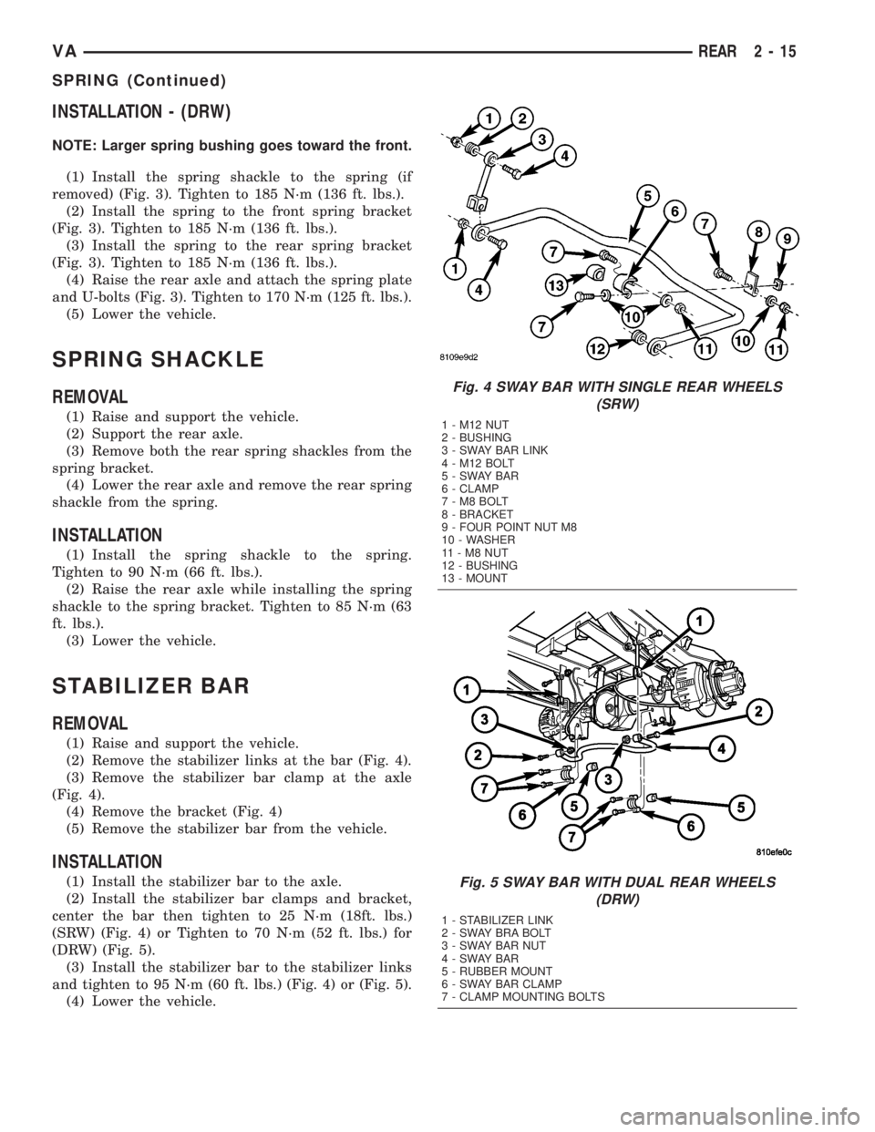
STABILIZER BAR
REMOVAL
(1) Raise and support the vehicle.
(2) Remove the stabilizer links at the bar (Fig. 4).
(3) Remove the stabilizer bar clamp at the axle
(Fig. 4).
(4) Remove the bracket (Fig. 4)
(5) Remove the stabilizer bar from the vehicle.
INSTALLATION
(1) Install the stabilizer bar to the axle.
(2) Install the stabilizer bar clamps and bracket,
center the bar then tighten to 25 N´m (18ft. lbs.)
(SRW) (Fig. 4) or Tighten to 70 N´m (52 ft. lbs.) for
(DRW) (Fig. 5).
(3) Install the stabilizer bar to the stabilizer links
and tighten to 95 N´m (60 ft. lbs.) (Fig. 4) or (Fig. 5).
(4) Lower the vehicle.
Fig. 4 SWAY BAR WITH SINGLE REAR WHEELS
(SRW)
1 - M12 NUT
2 - BUSHING
3 - SWAY BAR LINK
4 - M12 BOLT
5-SWAYBAR
6 - CLAMP
7-M8BOLT
8 - BRACKET
9 - FOUR POINT NUT M8
10 - WASHER
11-M8NUT
12 - BUSHING
13 - MOUNT
Fig. 5 SWAY BAR WITH DUAL REAR WHEELS
(DRW)
1 - STABILIZER LINK
2 - SWAY BRA BOLT
3 - SWAY BAR NUT
4-SWAYBAR
5 - RUBBER MOUNT
6 - SWAY BAR CLAMP
7 - CLAMP MOUNTING BOLTS
VAREAR 2 - 15
SPRING (Continued)
Page 52 of 1232
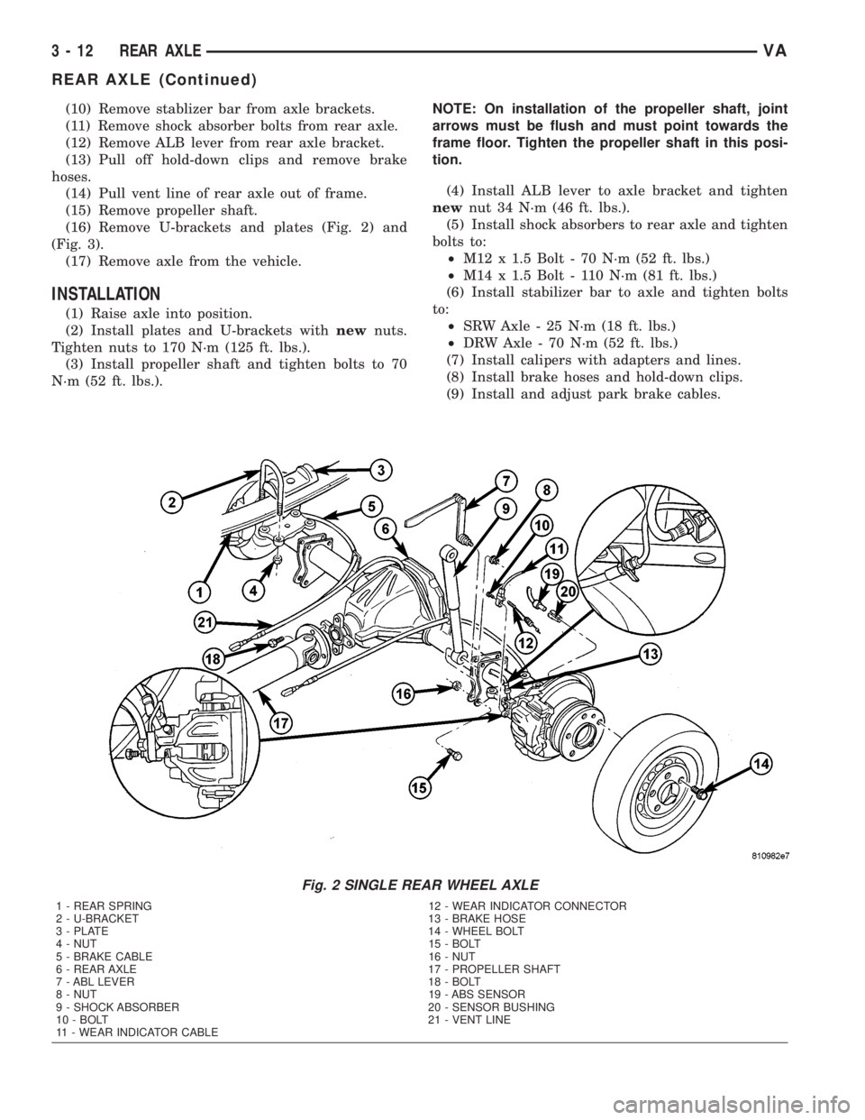
(10) Remove stablizer bar from axle brackets.
(11) Remove shock absorber bolts from rear axle.
(12) Remove ALB lever from rear axle bracket.
(13) Pull off hold-down clips and remove brake
hoses.
(14) Pull vent line of rear axle out of frame.
(15) Remove propeller shaft.
(16) Remove U-brackets and plates (Fig. 2) and
(Fig. 3).
(17) Remove axle from the vehicle.
INSTALLATION
(1) Raise axle into position.
(2) Install plates and U-brackets withnewnuts.
Tighten nuts to 170 N´m (125 ft. lbs.).
(3) Install propeller shaft and tighten bolts to 70
N´m (52 ft. lbs.).NOTE: On installation of the propeller shaft, joint
arrows must be flush and must point towards the
frame floor. Tighten the propeller shaft in this posi-
tion.
(4) Install ALB lever to axle bracket and tighten
newnut 34 N´m (46 ft. lbs.).
(5) Install shock absorbers to rear axle and tighten
bolts to:
²M12 x 1.5 Bolt - 70 N´m (52 ft. lbs.)
²M14 x 1.5 Bolt - 110 N´m (81 ft. lbs.)
(6) Install stabilizer bar to axle and tighten bolts
to:
²SRW Axle - 25 N´m (18 ft. lbs.)
²DRW Axle - 70 N´m (52 ft. lbs.)
(7) Install calipers with adapters and lines.
(8) Install brake hoses and hold-down clips.
(9) Install and adjust park brake cables.
Fig. 2 SINGLE REAR WHEEL AXLE
1 - REAR SPRING 12 - WEAR INDICATOR CONNECTOR
2 - U-BRACKET 13 - BRAKE HOSE
3 - PLATE 14 - WHEEL BOLT
4 - NUT 15 - BOLT
5 - BRAKE CABLE 16 - NUT
6 - REAR AXLE 17 - PROPELLER SHAFT
7 - ABL LEVER 18 - BOLT
8 - NUT 19 - ABS SENSOR
9 - SHOCK ABSORBER 20 - SENSOR BUSHING
10 - BOLT 21 - VENT LINE
11 - WEAR INDICATOR CABLE
3 - 12 REAR AXLEVA
REAR AXLE (Continued)
Page 289 of 1232
CHECK VALVE
DESCRIPTION
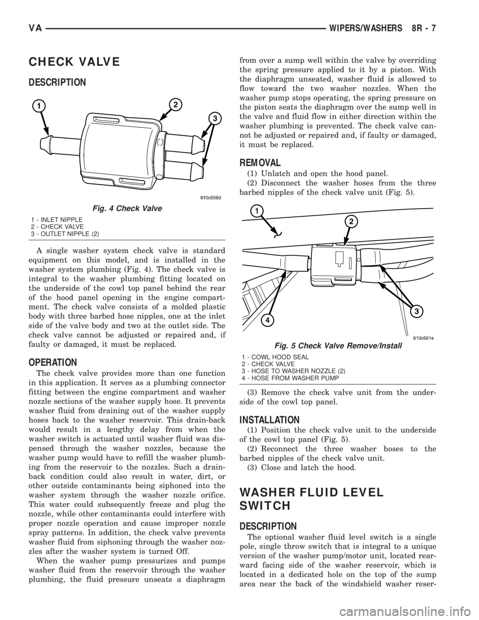
A single washer system check valve is standard
equipment on this model, and is installed in the
washer system plumbing (Fig. 4). The check valve is
integral to the washer plumbing fitting located on
the underside of the cowl top panel behind the rear
of the hood panel opening in the engine compart-
ment. The check valve consists of a molded plastic
body with three barbed hose nipples, one at the inlet
side of the valve body and two at the outlet side. The
check valve cannot be adjusted or repaired and, if
faulty or damaged, it must be replaced.
OPERATION
The check valve provides more than one function
in this application. It serves as a plumbing connector
fitting between the engine compartment and washer
nozzle sections of the washer supply hose. It prevents
washer fluid from draining out of the washer supply
hoses back to the washer reservoir. This drain-back
would result in a lengthy delay from when the
washer switch is actuated until washer fluid was dis-
pensed through the washer nozzles, because the
washer pump would have to refill the washer plumb-
ing from the reservoir to the nozzles. Such a drain-
back condition could also result in water, dirt, or
other outside contaminants being siphoned into the
washer system through the washer nozzle orifice.
This water could subsequently freeze and plug the
nozzle, while other contaminants could interfere with
proper nozzle operation and cause improper nozzle
spray patterns. In addition, the check valve prevents
washer fluid from siphoning through the washer noz-
zles after the washer system is turned Off.
When the washer pump pressurizes and pumps
washer fluid from the reservoir through the washer
plumbing, the fluid pressure unseats a diaphragmfrom over a sump well within the valve by overriding
the spring pressure applied to it by a piston. With
the diaphragm unseated, washer fluid is allowed to
flow toward the two washer nozzles. When the
washer pump stops operating, the spring pressure on
the piston seats the diaphragm over the sump well in
the valve and fluid flow in either direction within the
washer plumbing is prevented. The check valve can-
not be adjusted or repaired and, if faulty or damaged,
it must be replaced.
REMOVAL
(1) Unlatch and open the hood panel.
(2) Disconnect the washer hoses from the three
barbed nipples of the check valve unit (Fig. 5).
(3) Remove the check valve unit from the under-
side of the cowl top panel.
INSTALLATION
(1) Position the check valve unit to the underside
of the cowl top panel (Fig. 5).
(2) Reconnect the three washer hoses to the
barbed nipples of the check valve unit.
(3) Close and latch the hood.
WASHER FLUID LEVEL
SWITCH
DESCRIPTION
The optional washer fluid level switch is a single
pole, single throw switch that is integral to a unique
version of the washer pump/motor unit, located rear-
ward facing side of the washer reservoir, which is
located in a dedicated hole on the top of the sump
area near the back of the windshield washer reser-
Fig. 4 Check Valve
1 - INLET NIPPLE
2 - CHECK VALVE
3 - OUTLET NIPPLE (2)
Fig. 5 Check Valve Remove/Install
1 - COWL HOOD SEAL
2 - CHECK VALVE
3 - HOSE TO WASHER NOZZLE (2)
4 - HOSE FROM WASHER PUMP
VAWIPERS/WASHERS 8R - 7
Page 868 of 1232
GEAR
TABLE OF CONTENTS
page page
GEAR
DESCRIPTION..........................8
REMOVAL.............................8INSTALLATION..........................8
SPECIFICATIONS - TORQUE CHART.........9
GEAR
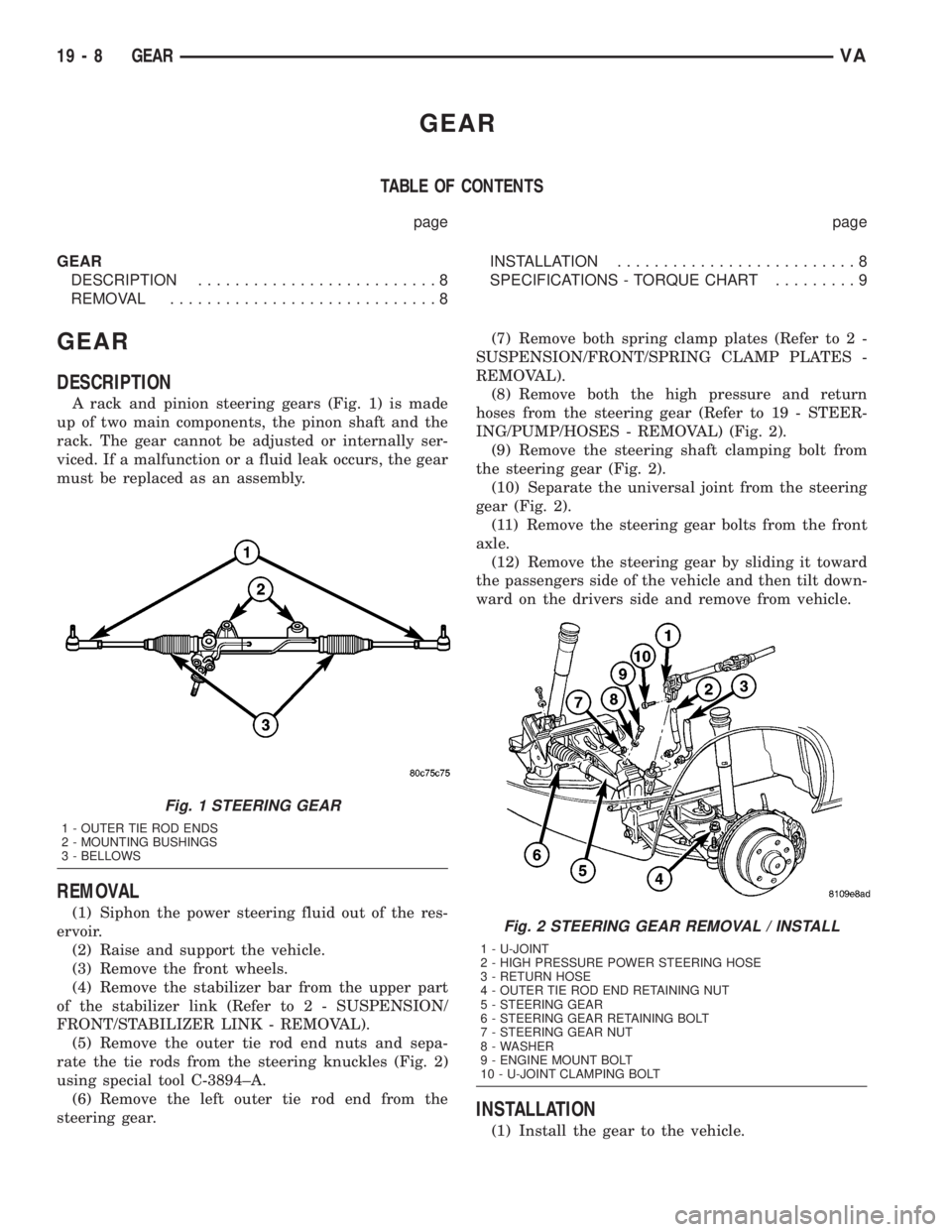
DESCRIPTION
A rack and pinion steering gears (Fig. 1) is made
up of two main components, the pinon shaft and the
rack. The gear cannot be adjusted or internally ser-
viced. If a malfunction or a fluid leak occurs, the gear
must be replaced as an assembly.
REMOVAL
(1) Siphon the power steering fluid out of the res-
ervoir.
(2) Raise and support the vehicle.
(3) Remove the front wheels.
(4) Remove the stabilizer bar from the upper part
of the stabilizer link (Refer to 2 - SUSPENSION/
FRONT/STABILIZER LINK - REMOVAL).
(5) Remove the outer tie rod end nuts and sepa-
rate the tie rods from the steering knuckles (Fig. 2)
using special tool C-3894±A.
(6) Remove the left outer tie rod end from the
steering gear.(7) Remove both spring clamp plates (Refer to 2 -
SUSPENSION/FRONT/SPRING CLAMP PLATES -
REMOVAL).
(8) Remove both the high pressure and return
hoses from the steering gear (Refer to 19 - STEER-
ING/PUMP/HOSES - REMOVAL) (Fig. 2).
(9) Remove the steering shaft clamping bolt from
the steering gear (Fig. 2).
(10) Separate the universal joint from the steering
gear (Fig. 2).
(11) Remove the steering gear bolts from the front
axle.
(12) Remove the steering gear by sliding it toward
the passengers side of the vehicle and then tilt down-
ward on the drivers side and remove from vehicle.
INSTALLATION
(1) Install the gear to the vehicle.
Fig. 1 STEERING GEAR
1 - OUTER TIE ROD ENDS
2 - MOUNTING BUSHINGS
3 - BELLOWS
Fig. 2 STEERING GEAR REMOVAL / INSTALL
1 - U-JOINT
2 - HIGH PRESSURE POWER STEERING HOSE
3 - RETURN HOSE
4 - OUTER TIE ROD END RETAINING NUT
5 - STEERING GEAR
6 - STEERING GEAR RETAINING BOLT
7 - STEERING GEAR NUT
8 - WASHER
9 - ENGINE MOUNT BOLT
10 - U-JOINT CLAMPING BOLT
19 - 8 GEARVA
Page 915 of 1232
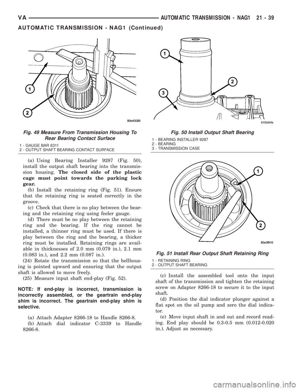
(a) Using Bearing Installer 9287 (Fig. 50),
install the output shaft bearing into the transmis-
sion housing.The closed side of the plastic
cage must point towards the parking lock
gear.
(b) Install the retaining ring (Fig. 51). Ensure
that the retaining ring is seated correctly in the
groove.
(c) Check that there is no play between the bear-
ing and the retaining ring using feeler gauge.
(d) There must be no play between the retaining
ring and the bearing. If the ring cannot be
installed, a thinner ring must be used. If there is
play between the ring and the bearing, a thicker
ring must be installed. Retaining rings are avail-
able in thicknesses of 2.0 mm (0.079 in.), 2.1 mm
(0.083 in.), and 2.2 mm (0.087 in.).
(24) Rotate the transmission so that the bellhous-
ing is pointed upward and ensuring that the output
shaft is allowed to move freely.
(25) Measure input shaft end-play (Fig. 52).
NOTE: If end-play is incorrect, transmission is
incorrectly assembled, or the geartrain end-play
shim is incorrect. The geartrain end-play shim is
selective.
(a) Attach Adapter 8266-18 to Handle 8266-8.
(b) Attach dial indicator C-3339 to Handle
8266-8.(c) Install the assembled tool onto the input
shaft of the transmission and tighten the retaining
screw on Adapter 8266-18 to secure it to the input
shaft.
(d) Position the dial indicator plunger against a
flat spot on the oil pump and zero the dial indica-
tor.
(e) Move input shaft in and out and record read-
ing. End play should be 0.3-0.5 mm (0.012-0.020
in.). Adjust as necessary.
Fig. 49 Measure From Transmission Housing To
Rear Bearing Contact Surface
1 - GAUGE BAR 6311
2 - OUTPUT SHAFT BEARING CONTACT SURFACE
Fig. 50 Install Output Shaft Bearing
1 - BEARING INSTALLER 9287
2 - BEARING
3 - TRANSMISSION CASE
Fig. 51 Install Rear Output Shaft Retaining Ring
1 - RETAINING RING
2 - OUTPUT SHAFT BEARING
VAAUTOMATIC TRANSMISSION - NAG1 21 - 39
AUTOMATIC TRANSMISSION - NAG1 (Continued)