2005 MERCEDES-BENZ SPRINTER engine overheat
[x] Cancel search: engine overheatPage 12 of 1232
engine to overheat because the specific heat of anti-
freeze is lower than that of water.
Use of 100 percent ethylene-glycol will cause for-
mation of additive deposits in the system, as the cor-
rosion inhibitive additives in ethylene-glycol require
the presence of water to dissolve. The deposits act as
insulation, causing temperatures to rise. The
increased temperature can result in engine detona-
tion. In addition, 100 percent ethylene-glycol freezes
at -22É C (-8É F ).
PROPYLENE-GLYCOL MIXTURES
It's overall effective temperature range is smaller
than that of ethylene-glycol. The freeze point of 50/50
propylene-glycol and water is -32É C (-26É F), 10É C
higher than ethylene-glycol's freeze point. The boiling
point (protection against summer boil-over) of propy-
lene-glycol is 125É C (257ÉF)at96.5 kPa (14 psi),
compared to 128É C (263É F) for ethylene-glycol. Pro-
pylene glycol also has slightly poorer heat transfer
characteristics than ethylene glycol. This can
increase cylinder head temperatures under certain
conditions.
Propylene-glycol/ethylene-glycol mixtures can cause
the destabilization of various corrosion inhibitors,
causing damage to the various cooling system compo-
nents. Also, once ethylene-glycol and propylene-glycol
based coolants are mixed in the vehicle, conventional
methods of determining freeze point will not be accu-
rate. Both the refractive index and specific gravity
differ between ethylene glycol and propylene glycol.
DESCRIPTION - HOAT COOLANT
WARNING: ANTIFREEZE IS AN ETHYLENE-GLYCOL
BASE COOLANT AND IS HARMFUL IF SWAL-
LOWED OR INHALED. IF SWALLOWED, DRINK
TWO GLASSES OF WATER AND INDUCE VOMIT-
ING. IF INHALED, MOVE TO FRESH AIR AREA.
SEEK MEDICAL ATTENTION IMMEDIATELY. DO NOT
STORE IN OPEN OR UNMARKED CONTAINERS.
WASH SKIN AND CLOTHING THOROUGHLY AFTER
COMING IN CONTACT WITH ETHYLENE-GLYCOL.
KEEP OUT OF REACH OF CHILDREN. DISPOSE OF
GLYCOL BASE COOLANT PROPERLY, CONTACT
YOUR DEALER OR GOVERNMENT AGENCY FOR
LOCATION OF COLLECTION CENTER IN YOUR
AREA. DO NOT OPEN A COOLING SYSTEM WHEN
THE ENGINE IS AT OPERATING TEMPERATURE OR
HOT UNDER PRESSURE, PERSONAL INJURY CAN
RESULT. AVOID RADIATOR COOLING FAN WHEN
ENGINE COMPARTMENT RELATED SERVICE IS
PERFORMED, PERSONAL INJURY CAN RESULT.CAUTION: Use of Propylene-Glycol based coolants
is not recommended, as they provide less freeze
protection and less corrosion protection.
The cooling system is designed around the coolant.
The coolant must accept heat from engine metal, in
the cylinder head area near the exhaust valves and
engine block. Then coolant carries the heat to the
radiator where the tube/fin radiator can transfer the
heat to the air.
The use of aluminum cylinder blocks, cylinder
heads, and water pumps requires special corrosion
protection. MopartAntifreeze/Coolant, 5
Year/100,000 Mile Formula (MS-9769), or the equiva-
lent ethylene-glycol base coolant with organic corro-
sion inhibitors (called HOAT, for Hybrid Organic
Additive Technology) is recommended. This coolant
offers the best engine cooling without corrosion when
mixed with 50% ethylene-glycol and 50% distilled
water to obtain a freeze point of -37ÉC (-34ÉF). If it
loses color or becomes contaminated, drain, flush,
and replace with fresh properly mixed coolant solu-
tion.
CAUTION: MoparTAntifreeze/Coolant, 5
Year/100,000 Mile Formula (MS-9769) may not be
mixed with any other type of antifreeze. Mixing of
coolants other than specified (non-HOAT), may
result in engine damage that may not be covered
under the new vehicle warranty, and decreased cor-
rosion protection.
COOLANT PERFORMANCE
The required ethylene-glycol (antifreeze) and water
mixture depends upon climate and vehicle operating
conditions. The coolant performance of various mix-
tures follows:
Pure Water-Water can absorb more heat than a
mixture of water and ethylene-glycol. This is for pur-
pose of heat transfer only. Water also freezes at a
higher temperature and allows corrosion.
100 percent Ethylene-Glycol-The corrosion
inhibiting additives in ethylene-glycol need the pres-
ence of water to dissolve. Without water, additives
form deposits in system. These act as insulation
causing temperature to rise. The increased tempera-
ture can result in engine detonation. In addition, 100
percent ethylene-glycol freezes at -22ÉC (-8ÉF).
50/50 Ethylene-Glycol and Water-Is the recom-
mended mixture, it provides protection against freez-
ing to -37ÉC (-34ÉF). The antifreeze concentration
must alwaysbe a minimum of 44 percent, year-
round in all climates. If percentage is lower, engine
parts may be eroded by cavitation. Maximum protec-
tion against freezing is provided with a 68 percent
antifreeze concentration, which prevents freezing
0 - 2 LUBRICATION & MAINTENANCEVA
FLUID TYPES (Continued)
Page 14 of 1232
Full synthetic oils, such as Mobilt1 0W-40, is
required if the ASSYST Oil Service Reminder is fol-
lowed. Use of a lower quality oil on this service
schedule may cause severe engine damage.
DESCRIPTION - AUTOMATIC TRANSMISSION
FLUID - NAG1
NOTE: Refer to Service Procedures in this group for
fluid level checking procedures.
Shellt3403 Automatic Transmission Fluid is the
recommended fluid for the NAG1 DaimlerChrysler
automatic transmission.
Dexron II fluid IS NOT recommended. Clutch
chatter can result from the use of improper
fluid.
MopartATF+4, Automatic Transmission Fluid, or
other fluids meeting MS-9602, may be used if Shellt
3403 Automatic Transmission Fluid is not available.
Shellt3403 Automatic Transmission Fluid when
new is red in color. The ATF is dyed red so it can be
identified from other fluids used in the vehicle such
as engine oil or antifreeze. The red color is not per-
manent and is not an indicator of fluid condition. As
the vehicle is driven, the ATF will begin to look
darker in color and may eventually become brown.
This is normal.
FLUID ADDITIVES
DaimlerChrysler strongly recommends against the
addition of any fluids to the transmission, other than
those automatic transmission fluids listed above.
Exceptions to this policy are the use of special dyes
to aid in detecting fluid leaks.
Various ªspecialº additives and supplements exist
that claim to improve shift feel and/or quality. These
additives and others also claim to improve converter
clutch operation and inhibit overheating, oxidation,
varnish, and sludge. These claims have not been sup-
ported to the satisfaction of DaimlerChrysler and
these additivesmust not be used.The use of trans-
mission ªsealersº should also be avoided, since they
may adversely affect the integrity of transmission
seals.
OPERATION - AUTOMATIC TRANSMISSION
FLUID
The automatic transmission fluid is selected based
upon several qualities. The fluid must provide a high
level of protection for the internal components by
providing a lubricating film between adjacent metal
components. The fluid must also be thermally stable
so that it can maintain a consistent viscosity through
a large temperature range. If the viscosity stays con-
stant through the temperature range of operation,transmission operation and shift feel will remain con-
sistent. Transmission fluid must also be a good con-
ductor of heat. The fluid must absorb heat from the
internal transmission components and transfer that
heat to the transmission case.
FLUID CAPACITIES
SPECIFICATIONS - FLUID CAPACITIES
DESCRIPTION SPECIFICATION
ENGINE COOLANT
10 Liters 10.5 Quarts
ENGINE OIL
9.0L with Filter
Replacement9.5 Quarts with Filter
Replacement
AUTOMATIC TRANSMISSION
Service Fill - NAG1 5.0 L (10.6 pts.)
O-haul Fill - NAG1 7.7 L (16.3 pts.)
Dry fill capacity Depending on type and size of
internal cooler, length and inside diameter of cooler
lines, or use of an auxiliary cooler, these figures may
vary. (Refer to appropriate 21 - TRANSMISSION/
AUTOMATIC/FLUID - STANDARD PROCEDURE).
REAR AXLE .03L (1 oz.)
8 1/2 1.8 L (4.0 pts.)
FUEL TANK
Primary 100 L (26.4 gal.)*
Reserve 10.5 L (2.8 gal.)*
*Nominal refill capacities are shown. A variation may
be observed from vehicle to vehicle due to
manufacturing tolerance and refill procedure
POWER STEERING SYSTEM
Power steering fluid capacities are dependent on
engine/chassis options as well as steering gear/cooler
options. Depending on type and size of internal
cooler, length and inside diameter of cooler lines, or
use of an auxiliary cooler, these capacities may vary.
Refer to 19, Steering for proper fill and bleed
procedures.
FLUID FILL/CHECK
LOCATIONS
INSPECTION - FLUID FILL/CHECK LOCATIONS
The fluid fill/check locations and lubrication points
are located in each applicable group.
0 - 4 LUBRICATION & MAINTENANCEVA
FLUID TYPES (Continued)
Page 67 of 1232
ROAD TESTING
(1) If complaint involved low brake pedal, pump
pedal and note if it comes back up to normal height.
(2) Check brake pedal response with transmission
in Neutral and engine running. Pedal should remain
firm under constant foot pressure.
(3) During road test, make normal and firm brake
stops in 25-40 mph range. Note faulty brake opera-
tion such as low pedal, hard pedal, fade, pedal pulsa-
tion, pull, grab, drag, noise, etc.
(4) Attempt to stop the vehicle with the parking
brake only and note grab, drag, noise, etc.
PEDAL FALLS AWAY
A brake pedal that falls away under steady foot
pressure is generally the result of a system leak. The
leak point could be at a brake line, fitting, hose, or
caliper/wheel cylinder. If leakage is severe, fluid will
be evident at or around the leaking component.
Internal leakage (seal by-pass) in the master cylin-
der caused by worn or damaged piston cups, may
also be the problem cause.
An internal leak in the ABS or RWAL system may
also be the problem with no physical evidence.
LOW PEDAL
If a low pedal is experienced, pump the pedal sev-
eral times. If the pedal comes back up worn linings,
rotors, drums, or rear brakes out of adjustment are
the most likely causes. The proper course of action is
to inspect and replace all worn component and make
the proper adjustments.
SPONGY PEDAL
A spongy pedal is most often caused by air in the
system. However, thin brake drums or substandard
brake lines and hoses can also cause a spongy pedal.
The proper course of action is to bleed the system,
and replace thin drums and substandard quality
brake hoses if suspected.
HARD PEDAL OR HIGH PEDAL EFFORT
A hard pedal or high pedal effort may be due to
lining that is water soaked, contaminated, glazed, or
badly worn. The power booster or check valve could
also be faulty.
PEDAL PULSATION
Pedal pulsation is caused by components that are
loose, or beyond tolerance limits.
The primary cause of pulsation are disc brake
rotors with excessive lateral runout or thickness vari-
ation, or out of round brake drums. Other causes are
loose wheel bearings or calipers and worn, damaged
tires.NOTE: Some pedal pulsation may be felt during
ABS activation.
BRAKE DRAG
Brake drag occurs when the lining is in constant
contact with the rotor or drum. Drag can occur at one
wheel, all wheels, fronts only, or rears only.
Drag is a product of incomplete brake shoe release.
Drag can be minor or severe enough to overheat the
linings, rotors and drums.
Minor drag will usually cause slight surface char-
ring of the lining. It can also generate hard spots in
rotors and drums from the overheat-cool down pro-
cess. In most cases, the rotors, drums, wheels and
tires are quite warm to the touch after the vehicle is
stopped.
Severe drag can char the brake lining all the way
through. It can also distort and score rotors and
drums to the point of replacement. The wheels, tires
and brake components will be extremely hot. In
severe cases, the lining may generate smoke as it
chars from overheating.
Common causes of brake drag are:
²Seized or improperly adjusted parking brake
cables.
²Loose/worn wheel bearing.
²Seized caliper or wheel cylinder piston.
²Caliper binding on corroded bushings or rusted
slide surfaces.
²Loose caliper mounting.
²Drum brake shoes binding on worn/damaged
support plates.
²Mis-assembled components.
²Long booster output rod.
If brake drag occurs at all wheels, the problem
may be related to a blocked master cylinder return
port, or faulty power booster (binds-does not release).
BRAKE FADE
Brake fade is usually a product of overheating
caused by brake drag. However, brake overheating
and resulting fade can also be caused by riding the
brake pedal, making repeated high deceleration stops
in a short time span, or constant braking on steep
mountain roads. Refer to the Brake Drag information
in this section for causes.
BRAKE PULL
Front brake pull condition could result from:
²Contaminated lining in one caliper
²Seized caliper piston
²Binding caliper
²Loose caliper
²Rusty caliper slide surfaces
²Improper brake pads
²Damaged rotor
VABRAKES - BASE 5 - 3
BRAKES - BASE (Continued)
Page 68 of 1232
A worn, damaged wheel bearing or suspension
component are further causes of pull. A damaged
front tire (bruised, ply separation) can also cause
pull.
A common and frequently misdiagnosed pull condi-
tion is where direction of pull changes after a few
stops. The cause is a combination of brake drag fol-
lowed by fade at one of the brake units.
As the dragging brake overheats, efficiency is so
reduced that fade occurs. Since the opposite brake
unit is still functioning normally, its braking effect is
magnified. This causes pull to switch direction in
favor of the normally functioning brake unit.
An additional point when diagnosing a change in
pull condition concerns brake cool down. Remember
that pull will return to the original direction, if the
dragging brake unit is allowed to cool down (and is
not seriously damaged).
REAR BRAKE GRAB OR PULL
Rear grab or pull is usually caused by improperly
adjusted or seized parking brake cables, contami-
nated lining, bent or binding shoes and support
plates, or improperly assembled components. This is
particularly true when only one rear wheel is
involved. However, when both rear wheels are
affected, the master cylinder or proportioning valve
could be at fault.
BRAKES DO NOT HOLD AFTER DRIVING THROUGH DEEP
WATER PUDDLES
This condition is generally caused by water soaked
lining. If the lining is only wet, it can be dried by
driving with the brakes very lightly applied for a
mile or two. However, if the lining is both soaked and
dirt contaminated, cleaning and/or replacement will
be necessary.
BRAKE LINING CONTAMINATION
Brake lining contamination is mostly a product of
leaking calipers or worn seals, driving through deep
water puddles, or lining that has become covered
with grease and grit during repair. Contaminated lin-
ing should be replaced to avoid further brake prob-
lems.
WHEEL AND TIRE PROBLEMS
Some conditions attributed to brake components
may actually be caused by a wheel or tire problem.
A damaged wheel can cause shudder, vibration and
pull. A worn or damaged tire can also cause pull.
Severely worn tires with very little tread left can
produce a grab-like condition as the tire loses and
recovers traction. Flat-spotted tires can cause vibra-
tion and generate shudder during brake operation. A
tire with internal damage such as a severe bruise,
cut, or ply separation can cause pull and vibration.BRAKE NOISES
Some brake noise is common with rear drum
brakes and on some disc brakes during the first few
stops after a vehicle has been parked overnight or
stored. This is primarily due to the formation of trace
corrosion (light rust) on metal surfaces. This light
corrosion is typically cleared from the metal surfaces
after a few brake applications causing the noise to
subside.
BRAKE SQUEAK/SQUEAL
Brake squeak or squeal may be due to linings that
are wet or contaminated with brake fluid, grease, or
oil. Glazed linings and rotors with hard spots can
also contribute to squeak. Dirt and foreign material
embedded in the brake lining will also cause squeak/
squeal.
A very loud squeak or squeal is frequently a sign of
severely worn brake lining. If the lining has worn
through to the brake pads in spots, metal-to-metal
contact occurs. If the condition is allowed to continue,
rotors can become so scored that replacement is nec-
essary.
BRAKE CHATTER
Brake chatter is usually caused by loose or worn
components, or glazed/burnt lining. Rotors with hard
spots can also contribute to chatter. Additional causes
of chatter are out-of-tolerance rotors, brake lining not
securely attached to the shoes, loose wheel bearings
and contaminated brake lining.
THUMP/CLUNK NOISE
Thumping or clunk noises during braking are fre-
quentlynotcaused by brake components. In many
cases, such noises are caused by loose or damaged
steering, suspension, or engine components. However,
calipers that bind on the slide surfaces can generate
a thump or clunk noise.
STANDARD PROCEDURE
STANDARD PROCEDURE - MANUAL BLEEDING
Use Mopar brake fluid, or an equivalent quality
fluid meeting SAE and DOT 4 standards only. Use
fresh, clean fluid from a sealed container at all times.
(1) Remove reservoir filler caps and fill reservoir.
(2) If calipers, or wheel cylinders were overhauled,
open all caliper and wheel cylinder bleed screws.
Then close each bleed screw as fluid starts to drip
from it. Top off master cylinder reservoir once more
before proceeding.
(3) Attach one end of bleed hose to bleed screw
and insert opposite end in glass container partially
filled with brake fluid (Fig. 1). Be sure end of bleed
hose is immersed in fluid.
5 - 4 BRAKES - BASEVA
BRAKES - BASE (Continued)
Page 97 of 1232
COOLING
TABLE OF CONTENTS
page page
COOLING
OPERATIONÐCOOLING SYSTEM...........1
DIAGNOSIS AND TESTING
DIAGNOSIS AND TESTING - PRELIMINARY
CHECKS.............................1DIAGNOSIS AND TESTING - COOLING
SYSTEM.............................2
ACCESSORY DRIVE.......................5
ENGINE................................9
COOLING
OPERATIONÐCOOLING SYSTEM
The cooling system regulates engine operating tem-
perature. It allows the engine to reach normal oper-
ating temperature as quickly as possible. It also
maintains normal operating temperature and pre-
vents overheating.
The cooling system also provides a means of heat-
ing the passenger compartment and cooling the auto-
matic transmission fluid (if equipped). The cooling
system is pressurized and uses a centrifugal water
pump to circulate coolant throughout the system.
DIAGNOSIS AND TESTING
DIAGNOSIS AND TESTING - PRELIMINARY
CHECKS
ENGINE COOLING SYSTEM OVERHEATING
Establish what driving conditions caused the com-
plaint. Abnormal loads on the cooling system such as
the following may be the cause:
²PROLONGED IDLE
²VERY HIGH AMBIENT TEMPERATURE
²SLIGHT TAIL WIND AT IDLE
²SLOW TRAFFIC
²TRAFFIC JAMS
²HIGH SPEED OR STEEP GRADES
Driving techniques that avoid overheating are:
²Idle with A/C off when temperature gauge is at
end of normal range.
²Increasing engine speed for more air flow is rec-
ommended.TRAILER TOWING:
Consult Trailer Towing section of owners manual.
Do not exceed limits.
AIR CONDITIONING; ADD-ON OR AFTER MARKET:
A maximum cooling package should have been
ordered with vehicle if add-on or after market A/C is
installed. If not, maximum cooling system compo-
nents should be installed for model involved per
manufacturer's specifications.
RECENT SERVICE OR ACCIDENT REPAIR:
Determine if any recent service has been per-
formed on vehicle that may effect cooling system.
This may be:
²Engine adjustments (incorrect timing)
²Slipping engine accessory drive belt(s)
²Brakes (possibly dragging)
²Changed parts. Incorrect water pump or pump
rotating in wrong direction due to belt not correctly
routed
²Reconditioned radiator or cooling system refill-
ing (possibly under filled or air trapped in system).
NOTE: If investigation reveals none of the previous
items as a cause for an engine overheating com-
plaint, (Refer to 7 - COOLING - DIAGNOSIS AND
TESTING)
VACOOLING 7 - 1
Page 104 of 1232
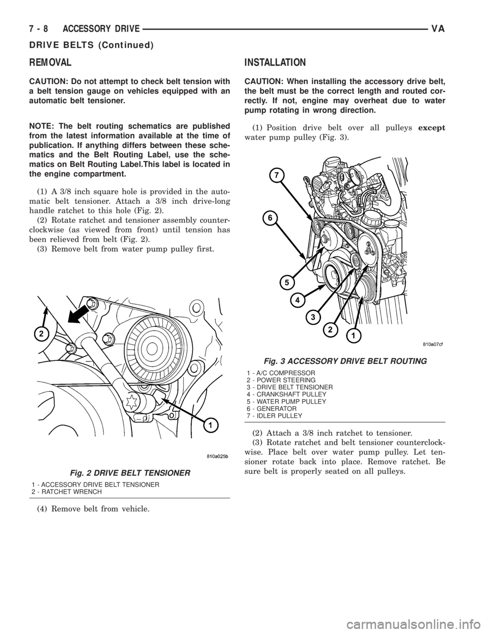
REMOVAL
CAUTION: Do not attempt to check belt tension with
a belt tension gauge on vehicles equipped with an
automatic belt tensioner.
NOTE: The belt routing schematics are published
from the latest information available at the time of
publication. If anything differs between these sche-
matics and the Belt Routing Label, use the sche-
matics on Belt Routing Label.This label is located in
the engine compartment.
(1) A 3/8 inch square hole is provided in the auto-
matic belt tensioner. Attach a 3/8 inch drive-long
handle ratchet to this hole (Fig. 2).
(2) Rotate ratchet and tensioner assembly counter-
clockwise (as viewed from front) until tension has
been relieved from belt (Fig. 2).
(3) Remove belt from water pump pulley first.
(4) Remove belt from vehicle.
INSTALLATION
CAUTION: When installing the accessory drive belt,
the belt must be the correct length and routed cor-
rectly. If not, engine may overheat due to water
pump rotating in wrong direction.
(1) Position drive belt over all pulleysexcept
water pump pulley (Fig. 3).
(2) Attach a 3/8 inch ratchet to tensioner.
(3) Rotate ratchet and belt tensioner counterclock-
wise. Place belt over water pump pulley. Let ten-
sioner rotate back into place. Remove ratchet. Be
sure belt is properly seated on all pulleys.
Fig. 2 DRIVE BELT TENSIONER
1 - ACCESSORY DRIVE BELT TENSIONER
2 - RATCHET WRENCH
Fig. 3 ACCESSORY DRIVE BELT ROUTING
1 - A/C COMPRESSOR
2 - POWER STEERING
3 - DRIVE BELT TENSIONER
4 - CRANKSHAFT PULLEY
5 - WATER PUMP PULLEY
6 - GENERATOR
7 - IDLER PULLEY
7 - 8 ACCESSORY DRIVEVA
DRIVE BELTS (Continued)
Page 105 of 1232
ENGINE
TABLE OF CONTENTS
page page
COOLANT
DESCRIPTION..........................9
DIAGNOSIS AND TESTING - COOLING
SYSTEM LEAKS......................10
STANDARD PROCEDURE
STANDARD PROCEDURE - ADDING
ADDITIONAL COOLANT.................11
STANDARD PROCEDURE - DRAINING
COOLING SYSTEM....................12
STANDARD PROCEDURE - REFILLING
COOLING SYSTEM....................12
COOLANT LEVEL SENSOR
REMOVAL.............................13
INSTALLATION.........................13
RADIATOR FAN
REMOVAL.............................13
INSTALLATION.........................13
ENGINE BLOCK HEATER
REMOVAL.............................14
INSTALLATION.........................14
ENGINE COOLANT TEMP SENSOR
DESCRIPTION.........................14REMOVAL.............................14
INSTALLATION.........................15
ENGINE COOLANT THERMOSTAT
REMOVAL.............................15
INSTALLATION.........................16
FAN DRIVE VISCOUS CLUTCH
REMOVAL.............................16
INSTALLATION.........................16
RADIATOR
REMOVAL.............................16
INSTALLATION.........................17
RADIATOR PRESSURE CAP
DESCRIPTION.........................18
OPERATION...........................18
DIAGNOSIS AND TESTING - RADIATOR
PRESSURE CAP......................19
WATER PUMP
REMOVAL.............................19
INSTALLATION.........................20
COOLANT
DESCRIPTION
Coolant flows through the engine water jackets and
cylinder heads absorbing heat produced by the engine
during operation. The coolant carries heat to the radia-
tor and heater core. Here it is transferred to ambient
air passing through the radiator and heater core fins.
The required ethylene-glycol (antifreeze) and water
mixture depends upon the climate and vehicle oper-
ating conditions. The recommended mixture of 50/50
ethylene-glycol and water will provide protection
against freezing to -37 deg. C (-35 deg. F). The anti-
freeze concentrationmust alwaysbe a minimum of
44 percent, year-round in all climates.If percentage
is lower than 44 percent, engine parts may be
eroded by cavitation, and cooling system com-
ponents may be severely damaged by corrosion.
Maximum protection against freezing is provided
with a 68 percent antifreeze concentration, which
prevents freezing down to -67.7 deg. C (-90 deg. F). A
higher percentage will freeze at a warmer tempera-
ture. Also, a higher percentage of antifreeze can
cause the engine to overheat because the specific
heat of antifreeze is lower than that of water.100 Percent Ethylene-GlycolÐShould Not Be Used in
Chrysler Vehicles
Use of 100 percent ethylene-glycol will cause forma-
tion of additive deposits in the system, as the corrosion
inhibitive additives in ethylene-glycol require the pres-
ence of water to dissolve. The deposits act as insulation,
causing temperatures to rise to as high as 149 deg. C
(300 deg. F). This temperature is hot enough to melt
plastic and soften solder. The increased temperature can
result in engine detonation. In addition, 100 percent
ethylene-glycol freezes at -22 deg. C (-8 deg. F ).
Propylene-glycol FormulationsÐShould Not Be Used in
Chrysler Vehicles
Propylene-glycol formulations do not meet
Chrysler coolant specifications.
It's overall effec-
tive temperature range is smaller than that of ethylene-
glycol. The freeze point of 50/50 propylene-glycol and
water is -32 deg. C (-26 deg. F). 5 deg. C higher than
ethylene-glycol's freeze point. The boiling point (protec-
tion against summer boil-over) of propylene-glycol is 125
deg. C (257 deg.F)at96.5 kPa (14 psi), compared to
128 deg. C (263 deg. F) for ethylene-glycol. Use of pro-
pylene-glycol can result in boil-over or freeze-up in
Chrysler vehicles, which are designed for ethylene-gly-
col. Propylene glycol also has poorer heat transfer char-
VAENGINE 7 - 9
Page 107 of 1232
Operate tester pump to apply 103.4 kPa (15 psi)
pressure to system. If hoses enlarge excessively or
bulges while testing, replace as necessary. Observe
gauge pointer and determine condition of cooling sys-
tem according to following criteria:
Holds Steady:If pointer remains steady for two
minutes, serious coolant leaks are not present in sys-
tem. However, there could be an internal leak that
does not appear with normal system test pressure. If
it is certain that coolant is being lost and leaks can-
not be detected, inspect for interior leakage or per-
form Internal Leakage Test.
Drops Slowly:Indicates a small leak or seepage
is occurring. Examine all connections for seepage or
slight leakage with a flashlight. Inspect radiator,
hoses, gasket edges and heater. Seal small leak holes
with a Sealer Lubricant (or equivalent). Repair leak
holes and inspect system again with pressure
applied.
Drops Quickly:Indicates that serious leakage is
occurring. Examine system for external leakage. If
leaks are not visible, inspect for internal leakage.
Large radiator leak holes should be repaired by a
reputable radiator repair shop.
INTERNAL LEAKAGE INSPECTION
Remove engine oil pan drain plug and drain a
small amount of engine oil. If coolant is present in
the pan, it will drain first because it is heavier than
oil. An alternative method is to operate engine for a
short period to churn the oil. After this is done,
remove engine dipstick and inspect for water glob-
ules. Also inspect transmission dipstick for water
globules and transmission fluid cooler for leakage.
WARNING: WITH RADIATOR PRESSURE TESTER
TOOL INSTALLED ON RADIATOR, DO NOT ALLOW
PRESSURE TO EXCEED 110 KPA (20 PSI). PRES-
SURE WILL BUILD UP QUICKLY IF A COMBUSTION
LEAK IS PRESENT. TO RELEASE PRESSURE,
ROCK TESTER FROM SIDE TO SIDE. WHEN
REMOVING TESTER, DO NOT TURN TESTER MORE
THAN 1/2 TURN IF SYSTEM IS UNDER PRESSURE.
Operate engine without pressure cap on coolant
container until thermostat opens. Attach a Pressure
Tester to container. If pressure builds up quickly it
indicates a combustion leak exists. This is usually
the result of a cylinder head gasket leak or crack in
engine. Repair as necessary.
If there is not an immediate pressure increase,
pump the Pressure Tester. Do this until indicated
pressure is within system range of 110 kPa (16 psi).
Fluctuation of gauge pointer indicates compression or
combustion leakage into cooling system.Because the vehicle is equipped with a catalytic
converter,do notremove spark plug cables or short
out cylinders to isolate compression leak.
If the needle on dial of pressure tester does not
fluctuate, race engine a few times to check for an
abnormal amount of coolant or steam. This would be
emitting from exhaust pipe. Coolant or steam from
exhaust pipe may indicate a faulty cylinder head gas-
ket, cracked engine cylinder block or cylinder head.
A convenient check for exhaust gas leakage into
cooling system is provided by a commercially avail-
able Block Leak Check tool. Follow manufacturers
instructions when using this product.
COMBUSTION LEAKAGE TEST - WITHOUT
PRESSURE TESTER
DO NOT WASTE reusable coolant. If solution is
clean, drain coolant into a clean and suitably marked
container for reuse.
WARNING: DO NOT REMOVE CYLINDER BLOCK
DRAIN PLUGS OR LOOSEN RADIATOR DRAIN
WITH SYSTEM HOT AND UNDER PRESSURE. SERI-
OUS BURNS FROM COOLANT CAN OCCUR.
Drain sufficient coolant to allow thermostat removal.
Remove accessory drive belt.
Add coolant to pressure container to bring level to
within 6.3 mm (1/4 in) of top of thermostat housing.
CAUTION: Avoid overheating. Do not operate
engine for an excessive period of time. Open drain-
cock immediately after test to eliminate boil over.
Start engine and accelerate rapidly three times, to
approximately 3000 rpm while observing coolant. If
internal engine combustion gases are leaking into
cooling system, bubbles will appear in coolant. If bub-
bles do not appear, internal combustion gas leakage
is not present.
STANDARD PROCEDURE
STANDARD PROCEDURE - ADDING
ADDITIONAL COOLANT
The use of aluminum cylinder blocks, cylinder
heads and water pumps requires special corrosion
protection. Only MopartAntifreeze/Coolant, 5
Year/100,000 Mile Formula (glycol base coolant with
corrosion inhibitors called HOAT, for Hybrid Organic
Additive Technology) is recommended. This coolant
offers the best engine cooling without corrosion when
mixed with 50% distilled water to obtain to obtain a
freeze point of -37ÉC (-35ÉF). If it loses color or
becomes contaminated, drain, flush, and replace with
fresh properly mixed coolant solution.
VAENGINE 7 - 11
COOLANT (Continued)