2005 MERCEDES-BENZ SPRINTER change key battery
[x] Cancel search: change key batteryPage 170 of 1232
GLOW PLUG RELAY
DESCRIPTION
The glow plug relay supplies battery voltage to the
glow plug through a timed cycle that is related to
coolant temperature. The glow plug relay is located
under the battery. The purpose of a glow plug system
is to improve combustion for low emissions and to
achieve easy starting at low temperatures.
OPERATION
When the ignition key is turned to the ON position,
the glow plug output stage and pre-glow indicator
lamp are actuated by the ECM. The duration of the
signal depends on the coolant temperature. The glow
plug relay has processing that communicates with the
ECM. If no data exchange occurs at the triggering
stage, the preheating is switched off after 2 seconds.
Start glowing is initiated when the key is in the
start position. The glow plugs (R13±R17) continue to
be supplied with voltage. This makes it possible to
stabilize the cold starting speed. (After glowing is ini-
tiated when the starter reject speed is reached).
After the engine starts, the ECM determines the
afterglow period in line with coolant temperature. If
no signal is received from the coolant temperature
sensor, afterglow is maintained for thirty seconds.
The following aims are reached by the afterglow :²Improvement in warming-up properties
²
Prevention of white exhaust smoke after cold start
²Stabilizing of the cold starting speed
The glow plug output stage constantly signals the
current operating state and faults. The following are
faults detected and transmitted to the ECM :
²Open circuit at one or several glow plugs
²Short circuit in the glow plug circuit
²Relay fault
If the Glow plug relay detects an open circuit at a
glow plug, it is stored and indicated only once the
engine is running by the preglow indicator lamp com-
ing on for about one minute and a fault is stored in
the ECM. If a short circuit, a glow plug output stage
faulty or a temperature related switching off of out-
put stages is detected, the fault is stored and indi-
cated immediately by the preglow indicator lamp
coming on. Once the fault is no longer current, the
indicator is immediately switched off, but the fault is
stored in the ECM. If the fault is constantly current,
the preglow indicator lamp remains on until the igni-
tion is switched off.
DIAGNOSIS AND TESTING - GLOW PLUG
RELAYS
Refer to the appropriate Diesel Powertrain Diagno-
sis Manual for information on diagnosing the glow
plug relays.
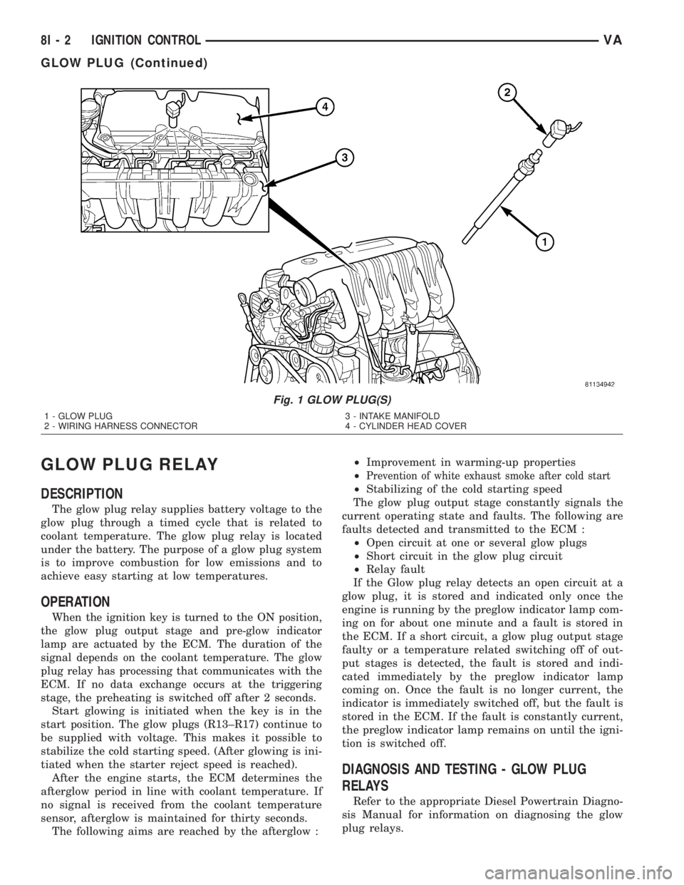
Fig. 1 GLOW PLUG(S)
1 - GLOW PLUG
2 - WIRING HARNESS CONNECTOR3 - INTAKE MANIFOLD
4 - CYLINDER HEAD COVER
8I - 2 IGNITION CONTROLVA
GLOW PLUG (Continued)
Page 175 of 1232
The EMIC modules for this model are serviced only
as complete units. The EMIC module cannot be
adjusted or repaired. If a gauge, an LED indicator,
the multi-fuction indicator LCD unit, an electronic
tone generator, the electronic circuit board, the cir-
cuit board hardware, the cluster overlay, the cluster
housing, the cluster hood, the cluster lens, or the
cluster rear cover are damaged or faulty, the entire
EMIC module must be replaced.
OPERATION
The ElectroMechanical Instrument Cluster (EMIC)
is designed to allow the vehicle operator to monitor
the conditions of many of the vehicle components and
operating systems. The gauges, meters and indicators
in the EMIC provide valuable information about the
powertrain, fuel and emissions systems, cooling sys-
tem, lighting systems, safety systems and many
other convenience items. The EMIC is installed in
the instrument panel so that all of these monitors
can be easily viewed by the vehicle operator when
driving, while still allowing relative ease of access for
service. The microprocessor-based EMIC hardware
and software uses various inputs to control the
gauges and indicators visible on the face of the clus-
ter. Some of these inputs are hard wired, but many
are in the form of electronic messages that are trans-
mitted by other electronic modules over the Control-
ler Area Network (CAN) data bus network. (Refer to
8 - ELECTRICAL/ELECTRONIC CONTROL MOD-
ULES/COMMUNICATION - OPERATION).
The EMIC microprocessor smooths the input data
using algorithms to provide gauge readings that are
accurate, stable and responsive to operating condi-
tions. These algorithms are designed to provide
gauge readings during normal operation that are con-
sistent with customer expectations. However, when
abnormal conditions exist such as high coolant tem-
perature, the algorithm can drive the gauge pointer
to an extreme position and the microprocessor can
sound a chime through the on-board audible tone
generator to provide distinct visual and audible indi-
cations of a problem to the vehicle operator. The
instrument cluster circuitry also provides audible
turn signal and hazard warning support by emulat-
ing the ªtickingº sound associated with a conven-
tional electro-mechanical flasher using a contactless
relay. The relay will also provide an indication of a
turn signal failure by sounding at double the usual
frequency. Each audible warning is provided to the
vehicle operator to supplement a visual indication.
The EMIC circuitry operates on battery current
received through a non-switched fused B(+) circuit,
and on a fused ignition switch output circuit. The
EMIC circuitry is grounded through a ground circuit
and take out of the frame wire harness with an eye-let terminal connector that is secured to a stud by a
nut at a ground location on the dash panel just for-
ward of the instrument cluster. Separate switched
ground inputs from the key-in ignition switch and
the front door jamb switches provide wake-up signals
to the EMIC circuitry. This arrangement allows the
EMIC to provide some features regardless of the igni-
tion switch position, while other features will operate
only with the ignition switch in the On position.
Proper diagnosis and testing of the EMIC, the
CAN data bus, the data bus electronic message
inputs to and outputs from the EMIC, as well as the
retrieval or erasure of a Diagnostic Trouble Code
(DTC) requires the use of a DRBIIItscan tool. Refer
to the appropriate diagnostic information. See the
owner's manual in the vehicle glove box for more
information on the features, use and operation of the
EMIC.
GAUGES
All gauges receive battery current through the
EMIC circuitry only when the instrument cluster
detects the ignition switch is in the On position. With
the ignition switch in the Off position, battery cur-
rent is not supplied to any gauges and the EMIC cir-
cuitry is programmed to move all of the gauge
needles back to the low end of their respective scales.
Therefore, the gauges do not accurately indicate any
vehicle condition unless the ignition switch is in the
On position.
All of the EMIC gauges are air core magnetic
units. Two fixed electromagnetic coils are located
within each gauge. These coils are wrapped at right
angles to each other around a movable permanent
magnet. The movable magnet is suspended within
the coils on one end of a pivot shaft, while the gauge
needle is attached to the other end of the shaft. One
of the coils has a fixed current flowing through it to
maintain a constant magnetic field strength. Current
flow through the second coil changes, which causes
changes in its magnetic field strength. The current
flowing through the second coil is changed by the
EMIC circuitry in response to messages received over
the CAN data bus. The gauge needle moves as the
movable permanent magnet aligns itself to the
changing magnetic fields created around it by the
electromagnets.
Proper diagnosis and testing of the gauges, the
CAN data bus and the electronic data bus message
inputs to the EMIC that control each gauge require
the use of a DRBIIItscan tool. Refer to the appro-
priate diagnostic information. Specific operation
details for each gauge may be found elsewhere in
this service information.
VAINSTRUMENT CLUSTER 8J - 5
INSTRUMENT CLUSTER (Continued)
Page 393 of 1232
8W-15 GROUND DISTRIBUTION
Component PageA/C Auxiliary Fan........................8W-15-4
A/C Auxiliary Fan Relay...................8W-15-12
A/C Control Module- Roof..................8W-15-28
A/C Fan Switch........................8W-15-21
A/C Switch- Roof.....................8W-15-24, 28
Airbag Control Module....................8W-15-11
Ash Receiver Lamp......................8W-15-22
Automatic Temperature Control Module.........8W-15-24
Auxiliary Heater Relay....................8W-15-12
Auxiliary Heater Switch...................8W-15-24
Battery..............................8W-15-8
Battery Relay- Auxiliary...................8W-15-11
Battery- Auxiliary.......................8W-15-11
Blower Motor- Front......................8W-15-9
Brake Fluid Level Switch...................8W-15-8
Brake Wear Sensor- Left Front................8W-15-8
Brake Wear Sensor- Left Rear...............8W-15-28
Brake Wear Sensor- Right Front...............8W-15-8
Brake Wear Sensor- Right Rear...............8W-15-28
Cabin Heater Assembly....................8W-15-3
Center High Mounted Stop Lamp..............8W-15-6
Central Timer Module....................8W-15-15
Cigar Lighter..........................8W-15-22
Cigar Lighter Lamp......................8W-15-22
Circulation Pump........................8W-15-9
Circulation Pump Relay...................8W-15-12
Clockspring...........................8W-15-10
Controller Antilock Brake.................8W-15-2, 28
CTEL Connector........................8W-15-21
Cylinder Lock Switch- Driver..............8W-15-7, 10
D+ Relay No. 1.........................8W-15-12
D+ Relay No. 2.........................8W-15-14
Data Link Connector.....................8W-15-10
Daytime Running Lamp Relay- Left Side.........8W-15-13
Daytime Running Lamp Relay- Right Side........8W-15-13
Daytime Running Lamps Relay...............8W-15-13
Differential Lock Solenoid Valve...............8W-15-2
Dome Lamp...........................8W-15-6
Dosing Pump...........................8W-15-2
Engine Control Module.....................8W-15-7
Engine Coolant Level Switch.................8W-15-2
Fan Stage 1 Relay.......................8W-15-11
Fog Lamp Relay........................8W-15-11
Fog Lamp Switch.......................8W-15-22
Fuse Block No. 1........................8W-15-7
Fused Ignition Switch Run-Start Relay..........8W-15-14
G100..............................8W-15-2, 3
G101................................8W-15-4
G102................................8W-15-4
G200.........................8W-15-6, 7, 8, 9, 10
G201...............................8W-15-11
G202.............8W-15-11, 12, 13, 14, 15, 16, 17, 18, 19
G203....................8W-15-20, 21, 22, 23, 24, 25
G300..........................8W-15-26, 27, 28
G301...............................8W-15-28
G302...............................8W-15-28
Glow Plug Control Module..................8W-15-2
Hazard Warning Switch....................8W-15-7
Headlamp Adjust Switch...................8W-15-22
Headlamp Assembly- Left...................8W-15-3
Headlamp Assembly- Right..................8W-15-4
Heat Exchanger Connector.................8W-15-12
Heat Exchanger Switch....................8W-15-24
Heated Seat Switch- Driver.................8W-15-25
Heated Seat Switch- Passenger...............8W-15-25
Heater Timer- Auxiliary...................8W-15-24
Hood Ajar Switch........................8W-15-4
Horn Relay...........................8W-15-11
Horn Switch..........................8W-15-10
Ignition Lock Switch.....................8W-15-10
Instrument Cluster......................8W-15-10
Instrument Panel Socket...................8W-15-20Component PageInterior Lamp No. 1......................8W-15-6
Interior Lamp No. 2......................8W-15-6
Interior Lamp No. 3......................8W-15-6
Interior Lamp No. 4......................8W-15-6
Interior Lamp No. 5......................8W-15-6
Interior Lamp- Middle Front................8W-15-5, 6
Interior Lamp- Middle Rear................8W-15-5, 6
Interior Lamp- Rear No. 2...................8W-15-5
Interior Lamp- Right Side.................8W-15-5, 6
Interior Light Switch.....................8W-15-21
Interior Lighting Connector..................8W-15-6
Intrusion Sensor No. 1.....................8W-15-6
Intrusion Sensor No. 2.....................8W-15-6
Intrusion Sensor No. 3.....................8W-15-6
Lamp Relay- Left.......................8W-15-13
Lamp Relay- Right......................8W-15-13
License Plate Lamp No. 1..................8W-15-27
License Plate Lamp No. 2..................8W-15-27
Locker Switch No. 1......................8W-15-20
Map/Reading Lamp Switch.................8W-15-21
Marker Lamp Connector...................8W-15-17
Marker Lamp No. 1- Left Front...............8W-15-16
Marker Lamp No. 1- Right Front..............8W-15-16
Marker Lamp No. 2- Left Front...............8W-15-16
Marker Lamp No. 2- Right Front..............8W-15-16
Marker Lamp- Left Center..................8W-15-17
Marker Lamp- Left Rear...................8W-15-27
Marker Lamp- Right Center.................8W-15-17
Marker Lamp- Right Rear..................8W-15-27
Master Door Lock Switch..................8W-15-25
Metering Pump.........................8W-15-18
Multi- Function Switch.....................8W-15-7
Optional Equipment Relay..................8W-15-19
Panic Alarm Switch......................8W-15-20
Parking Brake Switch....................8W-15-15
Power Mirror Motor- Driver.................8W-15-23
Power Mirror Motor- Passenger...............8W-15-23
Power Mirror Switch.....................8W-15-23
Power Window Switch- Driver...............8W-15-23
Power Window Switch- Master...............8W-15-23
Radio...............................8W-15-21
Reading Lamp Connector...................8W-15-6
Recirculated Air Solenoid Valve...............8W-15-9
Seat Belt Switch........................8W-15-15
Security System Module...................8W-15-15
Sentry Key Remote Entry Module..............8W-15-7
Shifter Assembly........................8W-15-20
Siren................................8W-15-9
Tail Lamp Assembly- Left..................8W-15-26
Tail Lamp Assembly- Right.................8W-15-26
TCS Switch...........................8W-15-25
Time Delay Relay.......................8W-15-17
Towing/Intrusion Sensor On/Off Switch..........8W-15-22
Trailer Tow Connector....................8W-15-28
Trailer Tow Control Module.................8W-15-19
Transmission Control Module................8W-15-19
Transmission Relay......................8W-15-19
Turn Signal No. 1- Left Front.................8W-15-3
Turn Signal No. 1- Right Front................8W-15-4
Turn Signal No. 2- Left Front.................8W-15-3
Warm Air Auxiliary Heater Assembly...........8W-15-18
Washer Pump Motor- Front..................8W-15-4
Water Cycle Valve........................8W-15-9
Window Defogger Module- Rear..............8W-15-15
Window Defogger Relay- Left Rear.............8W-15-14
Window Defogger Relay- Right Rear............8W-15-14
Window Defogger Switch- Rear...............8W-15-20
Window Defogger- Left Rear.................8W-15-26
Window Defogger- Right Rear................8W-15-26
Wiper Motor- Front.......................8W-15-9
Wiper/Turn Signal/Engine Start Control Module.....8W-15-7
VA8W-15 GROUND DISTRIBUTION 8W - 15 - 1