2005 MERCEDES-BENZ SPRINTER glove box
[x] Cancel search: glove boxPage 117 of 1232
AUDIO/VIDEO
TABLE OF CONTENTS
page page
AUDIO
SPECIAL TOOLS
AUDIO...............................1
ANTENNA BODY & CABLE
REMOVAL.............................1
INSTALLATION..........................1
INSTRUMENT PANEL ANTENNA CABLE
REMOVAL.............................1INSTALLATION..........................2
RADIO
REMOVAL.............................2
INSTALLATION..........................2
SPEAKER
REMOVAL.............................2
INSTALLATION..........................2
AUDIO
SPECIAL TOOLS
AUDIO
SPECIAL TOOL CROSS REFERENCE CHART
MB
TOOL #MILLER
TOOL #DESCRIPTION
000 589
88 63 009241 RADIO EXTRACTION
TOOL
ANTENNA BODY & CABLE
REMOVAL
(1) Disconnect and isolate the battery negative
cable.
(2) Remove the portion of the headliner over the
front seat passengers (Refer to 23 - BODY/INTERI-
OR/HEADLINER - REMOVAL).
(3) Disconnect the antenna and electrical connec-
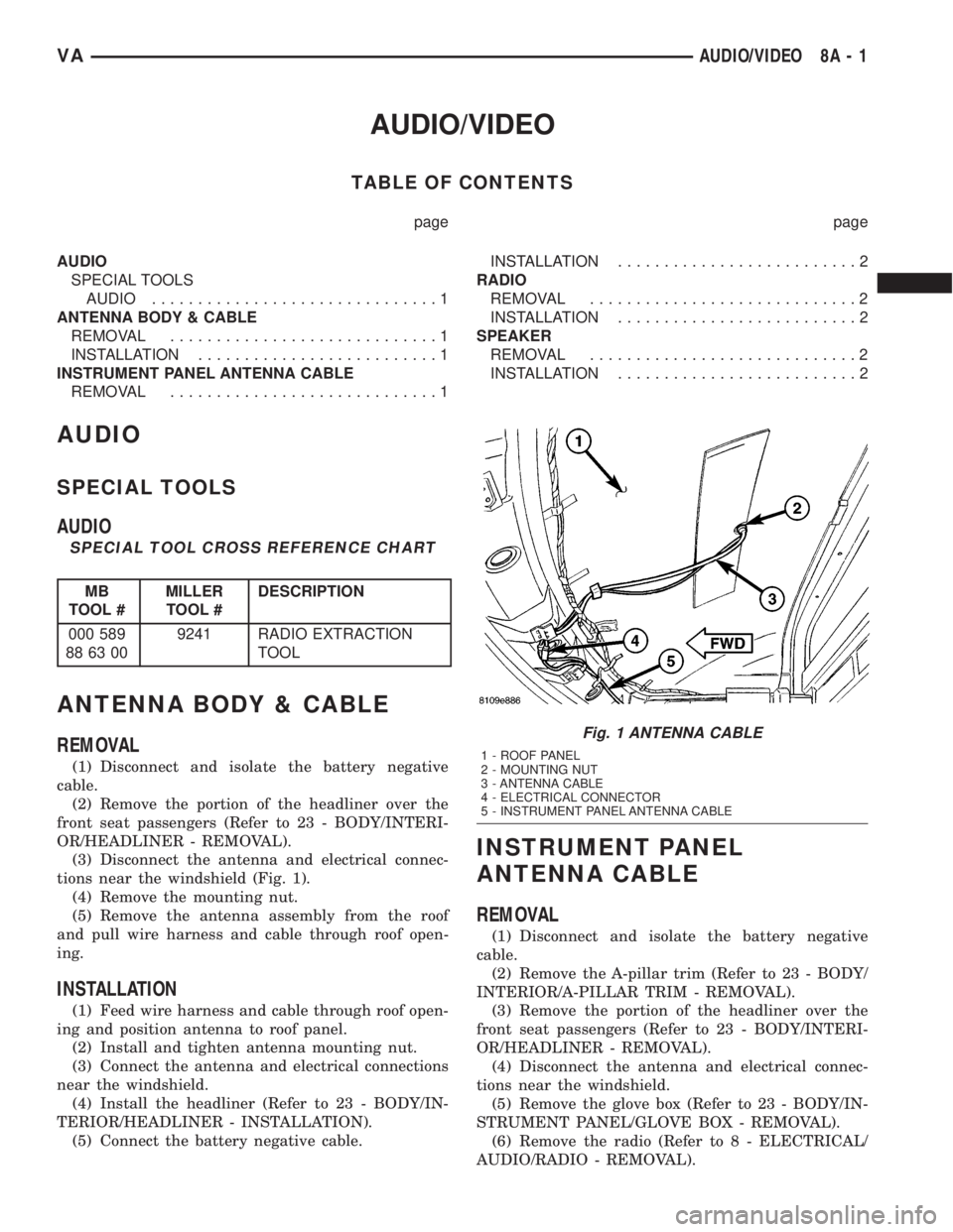
tions near the windshield (Fig. 1).
(4) Remove the mounting nut.
(5) Remove the antenna assembly from the roof
and pull wire harness and cable through roof open-
ing.
INSTALLATION
(1) Feed wire harness and cable through roof open-
ing and position antenna to roof panel.
(2) Install and tighten antenna mounting nut.
(3) Connect the antenna and electrical connections
near the windshield.
(4) Install the headliner (Refer to 23 - BODY/IN-
TERIOR/HEADLINER - INSTALLATION).
(5) Connect the battery negative cable.
INSTRUMENT PANEL
ANTENNA CABLE
REMOVAL
(1) Disconnect and isolate the battery negative
cable.
(2) Remove the A-pillar trim (Refer to 23 - BODY/
INTERIOR/A-PILLAR TRIM - REMOVAL).
(3) Remove the portion of the headliner over the
front seat passengers (Refer to 23 - BODY/INTERI-
OR/HEADLINER - REMOVAL).
(4) Disconnect the antenna and electrical connec-
tions near the windshield.
(5) Remove the glove box (Refer to 23 - BODY/IN-
STRUMENT PANEL/GLOVE BOX - REMOVAL).
(6) Remove the radio (Refer to 8 - ELECTRICAL/
AUDIO/RADIO - REMOVAL).
Fig. 1 ANTENNA CABLE
1 - ROOF PANEL
2 - MOUNTING NUT
3 - ANTENNA CABLE
4 - ELECTRICAL CONNECTOR
5 - INSTRUMENT PANEL ANTENNA CABLE
VAAUDIO/VIDEO 8A - 1
Page 118 of 1232
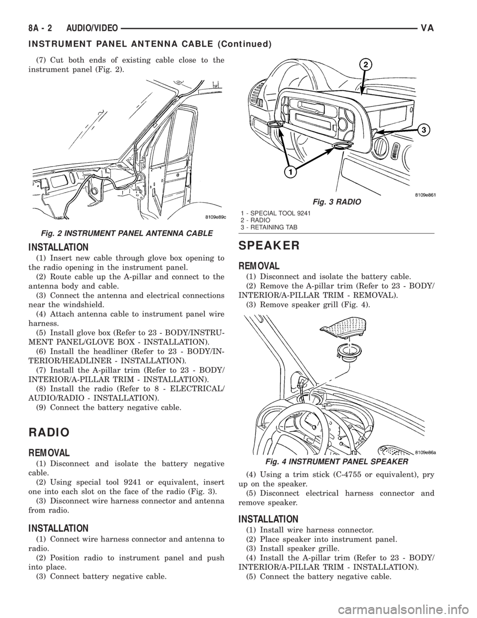
(7) Cut both ends of existing cable close to the
instrument panel (Fig. 2).
INSTALLATION
(1) Insert new cable through glove box opening to
the radio opening in the instrument panel.
(2) Route cable up the A-pillar and connect to the
antenna body and cable.
(3) Connect the antenna and electrical connections
near the windshield.
(4) Attach antenna cable to instrument panel wire
harness.
(5) Install glove box (Refer to 23 - BODY/INSTRU-
MENT PANEL/GLOVE BOX - INSTALLATION).
(6) Install the headliner (Refer to 23 - BODY/IN-
TERIOR/HEADLINER - INSTALLATION).
(7) Install the A-pillar trim (Refer to 23 - BODY/
INTERIOR/A-PILLAR TRIM - INSTALLATION).
(8) Install the radio (Refer to 8 - ELECTRICAL/
AUDIO/RADIO - INSTALLATION).
(9) Connect the battery negative cable.
RADIO
REMOVAL
(1) Disconnect and isolate the battery negative
cable.
(2) Using special tool 9241 or equivalent, insert
one into each slot on the face of the radio (Fig. 3).
(3) Disconnect wire harness connector and antenna
from radio.
INSTALLATION
(1) Connect wire harness connector and antenna to
radio.
(2) Position radio to instrument panel and push
into place.
(3) Connect battery negative cable.
SPEAKER
REMOVAL
(1) Disconnect and isolate the battery cable.
(2) Remove the A-pillar trim (Refer to 23 - BODY/
INTERIOR/A-PILLAR TRIM - REMOVAL).
(3) Remove speaker grill (Fig. 4).
(4) Using a trim stick (C-4755 or equivalent), pry
up on the speaker.
(5) Disconnect electrical harness connector and
remove speaker.
INSTALLATION
(1) Install wire harness connector.
(2) Place speaker into instrument panel.
(3) Install speaker grille.
(4) Install the A-pillar trim (Refer to 23 - BODY/
INTERIOR/A-PILLAR TRIM - INSTALLATION).
(5) Connect the battery negative cable.
Fig. 2 INSTRUMENT PANEL ANTENNA CABLE
Fig. 3 RADIO
1 - SPECIAL TOOL 9241
2 - RADIO
3 - RETAINING TAB
Fig. 4 INSTRUMENT PANEL SPEAKER
8A - 2 AUDIO/VIDEOVA
INSTRUMENT PANEL ANTENNA CABLE (Continued)
Page 120 of 1232
²Lights-On Warning- The EMIC chime tone
generator will generate repetitive chime tones at a
fast rate when either front door is opened with the
ignition switch in any position except On, and the
exterior lights are turned On. The EMIC uses inter-
nal programming and hard wired inputs from the left
(lighting) control stalk of the multi-function switch,
the ignition switch, and both front door jamb
switches to determine the current status of these
switches. This chime will continue to sound until the
exterior lighting is turned Off, until the ignition
switch is turned to the On position, or until both
front doors are closed, whichever occurs first.
²Key-In-Ignition Warning-
The EMIC chime
tone generator will generate repetitive chime tones at a
fast rate when the key is in the ignition lock cylinder,
the ignition switch is in any position except On, and
either front door is opened. The EMIC uses internal
programming and hard wired inputs from the key-in
ignition switch, the ignition switch, and both front door
jamb switches to determine the current status of these
switches. The chime will continue to sound until the key
is removed from the ignition lock cylinder, until the
ignition switch is turned to the On position, or until
both front doors are closed, whichever occurs first.
²Audible Turn Signal/Hazard Warning Sup-
port-
The EMIC contactless relay will generate repeti-
tive clicks at a slow rate during normal turn signal/
hazard warning operation, or at a fast rate when a turn
signal lamp bulb or circuit is inoperative, in concert with
the operation of the turn signal indicators in the cluster.
These clicks are designed to emulate the sound of the
opening and closing of the contact points in a conven-
tional electro-mechanical turn signal or hazard warning
flasher. The EMIC uses a hard wired input received from
the turn signal relay in the fuse block beneath the steer-
ing column through the turn signal or hazard warning
switch circuitry of the multi-function switch to determine
when to flash the turn signal indicators and activate the
contactless relay on the cluster electronic circuit board.
The turn signal clicks will continue to sound until the
turn signal switch is turned Off, or until the ignition
switch is turned to the Off position, whichever occurs
first. The hazard warning clicks will continue to sound
until the hazard warning switch is turned Off.
The EMIC provides chime service for all available
features in the chime warning system. The EMIC relies
upon its internal programming and hard wired inputs
from the front door ajar switches, the key-in ignition
switch, the ignition switch, the seat belt switch, and the
turn signal/hazard warning (multi-function) switches.
The EMIC relies upon electronic message inputs
received from other electronic modules over the CAN
data bus network to provide chime service for the low
engine oil level warning. Upon receiving the proper
inputs, the EMIC activates the chime tone generator orthe contactless relay to provide the audible warning to
the vehicle operator. The internal programming of the
EMIC determines the priority of each chime request
input that is received, as well as the rate and duration
of each tone that is to be generated. See the owner's
manual in the vehicle glove box for more information on
the features provided by the chime warning system.
The hard wired chime warning system inputs to
the EMIC, as well as other hard wired circuits for
this system may be diagnosed and tested using con-
ventional diagnostic tools and procedures. However,
conventional diagnostic methods may not prove con-
clusive in the diagnosis of the EMIC, the CAN data
bus network, or the electronic message inputs used
by the EMIC to provide chime warning system ser-
vice. The most reliable, efficient, and accurate means
to diagnose the EMIC, the CAN data bus network,
and the electronic message inputs for the chime
warning system requires the use of a DRBIIItscan
tool. Refer to the appropriate diagnostic information.
DIAGNOSIS AND TESTING - CHIME WARNING
SYSTEM
WARNING: ON VEHICLES EQUIPPED WITH AIRBAGS,
DISABLE THE SUPPLEMENTAL RESTRAINT SYSTEM
BEFORE ATTEMPTING ANY STEERING WHEEL,
STEERING COLUMN, DRIVER AIRBAG, PASSENGER
AIRBAG, SEAT BELT TENSIONER, OR INSTRUMENT
PANEL COMPONENT DIAGNOSIS OR SERVICE. DIS-
CONNECT AND ISOLATE THE BATTERY NEGATIVE
(GROUND) CABLE, THEN WAIT TWO MINUTES FOR
THE SYSTEM CAPACITOR TO DISCHARGE BEFORE
PERFORMING FURTHER DIAGNOSIS OR SERVICE.
THIS IS THE ONLY SURE WAY TO DISABLE THE SUP-
PLEMENTAL RESTRAINT SYSTEM. FAILURE TO TAKE
THE PROPER PRECAUTIONS COULD RESULT IN
ACCIDENTAL AIRBAG DEPLOYMENT AND POSSIBLE
PERSONAL INJURY.
The hard wired chime warning system inputs to
the Electro-Mechanical Instrument Cluster (EMIC),
as well as other hard wired circuits for this system
may be diagnosed and tested using conventional
diagnostic tools and procedures. However, conven-
tional diagnostic methods may not prove conclusive
in the diagnosis of the EMIC, the Controller Area
Network (CAN) data bus network, or the electronic
message inputs used by the EMIC to provide chime
warning system service. The most reliable, efficient,
and accurate means to diagnose the EMIC, the CAN
data bus network, and the electronic message inputs
for the chime warning system requires the use of a
DRBIIItscan tool. Refer to the appropriate diagnos-
tic information.
8B - 2 CHIME/BUZZERVA
CHIME/BUZZER (Continued)
Page 130 of 1232
²Battery Holddown- The battery holddown
hardware secures the battery in the battery tray in
the engine compartment.
²Battery Tray- The battery tray provides a
secure mounting location in the vehicle for the bat-
tery and an anchor point for the battery holddown
hardware.
For battery system maintenance schedules and
jump starting procedures, see the owner's manual in
the vehicle glove box. Optionally, refer to the Lubri-
cation and Maintenance section of this manual for
the recommended battery maintenance schedules and
for the proper battery jump starting procedure. While
battery charging can be considered a maintenance
procedure, the battery charging procedure and
related information are located later in this section of
this service manual. This was done because the bat-
tery must be fully-charged before any battery system
diagnosis or testing procedures can be performed.
OPERATION
The battery system is designed to provide a safe,
efficient, reliable and mobile means of delivering and
storing electrical energy. This electrical energy is
required to operate the engine starting system, as
well as to operate many of the other vehicle acces-
sory systems for limited durations while the engine
and/or the charging system are not operating. The
battery system is also designed to provide a reserve
of electrical energy to supplement the charging sys-
tem for short durations while the engine is running
and the electrical current demands of the vehicle
exceed the output of the charging system. In addition
to delivering, and storing electrical energy for the
vehicle, the battery system serves as a capacitor and
voltage stabilizer for the vehicle electrical system. It
absorbs most abnormal or transient voltages caused
by the switching of any of the electrical components
or circuits in the vehicle.
DIAGNOSIS AND TESTING - BATTERY SYSTEM
The battery, starting, and charging systems in the
vehicle operate with one another and must be testedas a complete system. In order for the engine to start
and the battery to maintain its charge properly, all of
the components that are used in these systems must
perform within specifications. It is important that
the battery, starting, and charging systems be thor-
oughly tested and inspected any time a battery needs
to be charged or replaced. The cause of abnormal bat-
tery discharge, overcharging or early battery failure
must be diagnosed and corrected before a battery is
replaced and before a vehicle is returned to service.
The service information for these systems has been
separated within this service manual to make it eas-
ier to locate the specific information you are seeking.
However, when attempting to diagnose any of these
systems, it is important that you keep their interde-
pendency in mind.
The diagnostic procedures used for the battery,
starting, and charging systems include the most
basic conventional diagnostic methods, to the more
sophisticated On-Board Diagnostics (OBD) built into
the Powertrain Control Module (PCM). Use of an
induction-type milliampere ammeter, a volt/ohmme-
ter, a battery charger, a carbon pile rheostat (load
tester) and a 12-volt test lamp may be required. All
OBD-sensed systems are monitored by the PCM.
Each monitored circuit is assigned a Diagnostic Trou-
ble Code (DTC). The PCM will store a DTC in elec-
tronic memory for any failure it detects. Refer to
Charging System for the proper charging system on-
board diagnostic test procedures.
MICRO 420 BATTERY TESTER
The Micro 420 automotive battery tester is
designed to help the dealership technicians diagnose
the cause of a defective battery. Follow the instruc-
tion manual supplied with the tester to properly
diagnose a vehicle. If the instruction manual is not
available refer to the standard procedure in this sec-
tion, which includes the directions for using the
Micro 420 battery tester.
8F - 2 BATTERY SYSTEMVA
BATTERY SYSTEM (Continued)
Page 175 of 1232
The EMIC modules for this model are serviced only
as complete units. The EMIC module cannot be
adjusted or repaired. If a gauge, an LED indicator,
the multi-fuction indicator LCD unit, an electronic
tone generator, the electronic circuit board, the cir-
cuit board hardware, the cluster overlay, the cluster
housing, the cluster hood, the cluster lens, or the
cluster rear cover are damaged or faulty, the entire
EMIC module must be replaced.
OPERATION
The ElectroMechanical Instrument Cluster (EMIC)
is designed to allow the vehicle operator to monitor
the conditions of many of the vehicle components and
operating systems. The gauges, meters and indicators
in the EMIC provide valuable information about the
powertrain, fuel and emissions systems, cooling sys-
tem, lighting systems, safety systems and many
other convenience items. The EMIC is installed in
the instrument panel so that all of these monitors
can be easily viewed by the vehicle operator when
driving, while still allowing relative ease of access for
service. The microprocessor-based EMIC hardware
and software uses various inputs to control the
gauges and indicators visible on the face of the clus-
ter. Some of these inputs are hard wired, but many
are in the form of electronic messages that are trans-
mitted by other electronic modules over the Control-
ler Area Network (CAN) data bus network. (Refer to
8 - ELECTRICAL/ELECTRONIC CONTROL MOD-
ULES/COMMUNICATION - OPERATION).
The EMIC microprocessor smooths the input data
using algorithms to provide gauge readings that are
accurate, stable and responsive to operating condi-
tions. These algorithms are designed to provide
gauge readings during normal operation that are con-
sistent with customer expectations. However, when
abnormal conditions exist such as high coolant tem-
perature, the algorithm can drive the gauge pointer
to an extreme position and the microprocessor can
sound a chime through the on-board audible tone
generator to provide distinct visual and audible indi-
cations of a problem to the vehicle operator. The
instrument cluster circuitry also provides audible
turn signal and hazard warning support by emulat-
ing the ªtickingº sound associated with a conven-
tional electro-mechanical flasher using a contactless
relay. The relay will also provide an indication of a
turn signal failure by sounding at double the usual
frequency. Each audible warning is provided to the
vehicle operator to supplement a visual indication.
The EMIC circuitry operates on battery current
received through a non-switched fused B(+) circuit,
and on a fused ignition switch output circuit. The
EMIC circuitry is grounded through a ground circuit
and take out of the frame wire harness with an eye-let terminal connector that is secured to a stud by a
nut at a ground location on the dash panel just for-
ward of the instrument cluster. Separate switched
ground inputs from the key-in ignition switch and
the front door jamb switches provide wake-up signals
to the EMIC circuitry. This arrangement allows the
EMIC to provide some features regardless of the igni-
tion switch position, while other features will operate
only with the ignition switch in the On position.
Proper diagnosis and testing of the EMIC, the
CAN data bus, the data bus electronic message
inputs to and outputs from the EMIC, as well as the
retrieval or erasure of a Diagnostic Trouble Code
(DTC) requires the use of a DRBIIItscan tool. Refer
to the appropriate diagnostic information. See the
owner's manual in the vehicle glove box for more
information on the features, use and operation of the
EMIC.
GAUGES
All gauges receive battery current through the
EMIC circuitry only when the instrument cluster
detects the ignition switch is in the On position. With
the ignition switch in the Off position, battery cur-
rent is not supplied to any gauges and the EMIC cir-
cuitry is programmed to move all of the gauge
needles back to the low end of their respective scales.
Therefore, the gauges do not accurately indicate any
vehicle condition unless the ignition switch is in the
On position.
All of the EMIC gauges are air core magnetic
units. Two fixed electromagnetic coils are located
within each gauge. These coils are wrapped at right
angles to each other around a movable permanent
magnet. The movable magnet is suspended within
the coils on one end of a pivot shaft, while the gauge
needle is attached to the other end of the shaft. One
of the coils has a fixed current flowing through it to
maintain a constant magnetic field strength. Current
flow through the second coil changes, which causes
changes in its magnetic field strength. The current
flowing through the second coil is changed by the
EMIC circuitry in response to messages received over
the CAN data bus. The gauge needle moves as the
movable permanent magnet aligns itself to the
changing magnetic fields created around it by the
electromagnets.
Proper diagnosis and testing of the gauges, the
CAN data bus and the electronic data bus message
inputs to the EMIC that control each gauge require
the use of a DRBIIItscan tool. Refer to the appro-
priate diagnostic information. Specific operation
details for each gauge may be found elsewhere in
this service information.
VAINSTRUMENT CLUSTER 8J - 5
INSTRUMENT CLUSTER (Continued)
Page 184 of 1232
using the ª+º (plus) and ª2º (minus) multi-function
indicator push buttons. The clock is serviced as a
unit with the instrument cluster.
OPERATION
The clock gives an indication to the vehicle opera-
tor of the current time. The electronic digital clock is
controlled by the instrument cluster microprocessor
based upon cluster programming. The clock display is
completely controlled by the instrument cluster logic
circuit, and that logic will only allow this indication
to be viewed when the multi-function indicator Liq-
uid Crystal Display (LCD) is activated. However, the
clock remains functional regardless of the ignition
switch position.
The vehicle operator can choose to have the
optional ambient temperature indicator displayed
instead of the clock information, but the clock and
ambient temperature indicator cannot be displayed
at the same time. The clock or ambient temperature
indicator display option is selected using the multi-
function indicator clock switch on the instrument
cluster circuit board. This switch is actuated manu-
ally by depressing the clock switch push button that
extends through the lower edge of the cluster lens
below the left end of the multi-function indicator.
Actuating this switch momentarily will toggle the
display between the clock and ambient temperature
indicator modes. Actuating this switch twice within
about one second will cause the display to toggle, but
then automatically revert to the originally selected
mode after about twenty seconds.
See the owner's manual in the vehicle glove box for
more information on the features, use, operation and
setting procedures for the clock. For proper testing of
the instrument cluster circuitry that controls the
clock functions, a DRBIIItscan tool is required.
Refer to the appropriate diagnostic information.
COOLANT LOW INDICATOR
DESCRIPTION
A coolant low indicator is standard equipment on
all instrument clusters. The coolant low indicator is
located near the lower edge of the instrument cluster,
to the left of the multi-function indicator display. The
coolant low indicator consists of the International
Control and Display Symbol icon for ªLow Engine
Coolantº imprinted within a rectangular cutout in
the opaque layer of the instrument cluster overlay.
The dark outer layer of the overlay prevents the indi-
cator from being clearly visible when it is not illumi-
nated. A red Light Emitting Diode (LED) behind the
cutout in the opaque layer of the overlay causes the
icon to appear silhouetted against a red field throughthe translucent outer layer of the overlay when the
indicator is illuminated from behind by the LED,
which is soldered onto the instrument cluster elec-
tronic circuit board. The coolant low indicator is ser-
viced as a unit with the instrument cluster.
OPERATION
The coolant low indicator gives an indication to the
vehicle operator when the engine coolant level is low.
This indicator is controlled by a transistor on the
instrument cluster circuit board based upon cluster
programming and a hard wired input received by the
cluster from the engine coolant level switch. The cool-
ant low indicator Light Emitting Diode (LED) is com-
pletely controlled by the instrument cluster logic
circuit, and that logic will only allow this indicator to
operate when the instrument cluster detects that the
ignition switch is in the On position. Therefore, the
LED will always be off when the ignition switch is in
any position except On. The LED only illuminates
when it is provided a path to ground by the instru-
ment cluster transistor. The instrument cluster will
turn on the coolant low indicator for the following
reasons:
²Bulb Test- Each time the ignition switch is
turned to the On position the coolant low indicator is
illuminated for about two seconds as a bulb test.
²Engine Coolant Level Switch Input- Each
time the cluster detects an appropriate input on the
low coolant fluid level sense circuit (engine coolant
level switch resistance low = engine coolant level low)
while the ignition switch is in the On position, the
coolant low indicator will be illuminated. The indica-
tor remains illuminated until the low coolant fluid
level sense input to the cluster changes (engine cool-
ant level switch resistance high = engine coolant
level full), or until the ignition switch is turned to
the Off position, whichever occurs first. The engine
coolant level switch also features a diagnostic resis-
tor connected in parallel between the switch input
and output to provide the cluster with verification
that the low coolant fluid level sense circuit is not
open or shorted.
The engine coolant level switch integral to the cool-
ant bottle provides a hard wired input to the instru-
ment cluster circuitry through the low coolant fluid
level sense circuit. The engine coolant level switch
and the low coolant fluid level sense circuit to the
instrument cluster can be diagnosed using conven-
tional diagnostic tools and methods. For proper diag-
nosis of the instrument cluster circuitry that controls
the coolant low indicator, a DRBIIItscan tool is
required. Refer to the appropriate diagnostic infor-
mation.
8J - 14 INSTRUMENT CLUSTERVA
CLOCK (Continued)
Page 189 of 1232
ule (ECM) over the Controller Area Network (CAN)
data bus. The low oil level indicator Light Emitting
Diode (LED) is completely controlled by the instru-
ment cluster logic circuit, and that logic will only
allow this indicator to operate when the instrument
cluster detects that the ignition switch is in the On
position. Therefore, the LED will always be off when
the ignition switch is in any position except On. The
LED only illuminates when it is provided a path to
ground by the instrument cluster transistor. The
instrument cluster will turn on the low oil level indi-
cator for the following reasons:
²Bulb Test- Each time the ignition switch is
turned to the On position the low oil level indicator
is illuminated for about two seconds as a bulb test.
²Engine Oil Level Low Message- Once the
engine has been started, each time the cluster
receives a message from the ECM indicating that the
engine oil level is at or near the ªMinimumº mark on
the dipstick, the low oil level indicator is illuminated.
The indicator remains illuminated briefly at first, but
will remain illuminated for longer periods as subse-
quent messages indicate that the oil level has
dropped further. Eventually, the indicator will
remain illuminated solid until the engine oil level is
corrected, or until the ignition switch is turned to the
Off position, whichever occurs first.
The instrument cluster also supplements the oil level
indicator by displaying an engine oil icon along with
alpha-numeric messages in the multi-function indicator
Liquid Crystal Display (LCD) advising the vehicle oper-
ator how much oil is required to correct the engine oil
level, and when the ªMaximumº engine oil level has
been exceeded. See the owner's manual in the vehicle
glove box for more information on this feature.
The ECM continually monitors the engine oil level
and temperature sensor to determine the engine oil
level. The ECM then sends the proper engine oil
level messages to the instrument cluster. If the
instrument cluster turns on the indicator after the
bulb test, even after the engine oil level is sufficient,
it may indicate that the engine or the engine oiling
system requires service. For proper diagnosis of the
engine oil level and temperature sensor, the ECM,
the CAN data bus, or the electronic message inputs
to the instrument cluster that control the low oil
level indicator, a DRBIIItscan tool is required. Refer
to the appropriate diagnostic information.
MAINTENANCE INDICATOR
DESCRIPTION
An Active Service SYSTem (ASSYST) engine oil main-
tenance indicator is optional equipment on all instru-
ment clusters. In vehicles so equipped, a second,dedicated ASSYST microprocessor is integral to the
cluster electronic circuit board. The ASSYST indications
are displayed and can be toggled with the clock indica-
tion on the right side of the multi-function indicator
Liquid Crystal Display (LCD) located near the lower
edge of the instrument cluster, directly below the speed-
ometer. The ASSYST displays include numeric values
combined with several icons to indicate actual engine oil
level, and reminders in time (days) or distance (miles or
kilometers) until the next required engine oil mainte-
nance is anticipated. ASSYST also provides several
audible indications using the electronic tone generator
on the instrument cluster circuit board to supplement
these visual displays.
The indications of the ASSYST engine oil mainte-
nance indicator are not visible when the LCD is not illu-
minated. When illuminated, the ASSYST indications
appear as dark characters and icons silhouetted against
an amber field. When the exterior lighting is turned Off,
the display is illuminated at maximum brightness.
When the exterior lighting is turned On, the display
illumination level can be adjusted in concert with the
cluster general illumination lighting using the ª+º (plus)
and ª2º (minus) multi-function indicator push buttons.
The ASSYST engine oil maintenance indicator is ser-
viced as a unit with the instrument cluster.
OPERATION
The ASSYST engine oil maintenance indicator micro-
processor uses numerous criteria besides time and mile-
age to evaluate vehicle maintenance requirements. Time
data is taken from the electronic digital clock integral to
the instrument cluster. Vehicle distance data is obtained
from the Controller Antilock Brake (CAB) over the Con-
troller Area Network (CAN) data bus. Coolant tempera-
ture, engine oil temperature, engine oil level, engine oil
quality, engine speed, and engine load data are obtained
from the Engine Control Module (ECM) over the CAN
data bus. Using all of the available data and internal
programming, the ASSYST microprocessor then calcu-
lates the estimated time and distance to the next
required engine oil maintenance interval. The ASSYST
uses the multi-function indicator LCD to display that
data and, when necessary, issues audible alerts to the
vehicle operator through the electronic tone generator
on the cluster circuit board.
See the owner's manual in the vehicle glove box for
more information on the features, use, operation and
resetting procedures for the ASSYST maintenance
computer. Proper diagnosis and testing of the
ASSYST engine oil maintenance computer, the CAN
data bus and the electronic data bus message inputs
to the EMIC that are used by the ASSYST computer
for its calculations requires the use of a DRBIIIt
scan tool. Refer to the appropriate diagnostic infor-
mation.
VAINSTRUMENT CLUSTER 8J - 19
LOW OIL LEVEL INDICATOR (Continued)
Page 191 of 1232
OPERATION
The multi-function indicator has several display
capabilities including odometer, trip odometer, clock,
engine oil level data, gear selector indicator
(PRNDL), certain diagnostic information and, on
vehicles so equipped, an optional Active Service SYS-
Tem (ASSYST) engine oil maintenance indicator and
an optional outside ambient temperature indicator.
The multi-function indicator is completely controlled
by the instrument cluster logic circuit, and that logic
will allow this indication to be viewed whenever the
multi-function indicator Liquid Crystal Display
(LCD) is activated. Therefore, the indicator remains
functional regardless of the ignition switch position.
With the ignition switch in the Off or Accessory posi-
tions and the key removed from the ignition lock cyl-
inder, the display is activated when the park lamps
are turned On or, for about thirty seconds after any
one of the multi-function indicator switch push but-
tons is depressed. Otherwise, the display unit is
active for about thirty seconds after the key is
inserted into the ignition lock cylinder, and inactive
about thirty seconds after the key is removed from
the ignition lock cylinder.
The multi-function indicator ªmiº (miles) or
ªkmº(kilometers) switch push button is used to con-
trol the odometer/trip odometer display modes. The
multi-function indicator clock switch push button is
used to control the clock/outside temperature display
modes. The multi-function indicator ª+º (plus) and
ª2º (minus) switch push buttons are used to adjust
the cluster general illumination dimming level, the
clock, and other cluster settings. See the owner's
manual in the vehicle glove box for more information
on the features, use, operation and setting proce-
dures for the various standard and optional multi-
function indicator displays.
Proper testing of the multi-function indicator LCD
unit, the CAN data bus and the electronic data bus
message inputs to the instrument cluster that control
some of the multi-function indicator functions
requires the use of a DRBIIItscan tool. Refer to the
appropriate diagnostic information. Additional details
for the odometer/trip odometer, the clock, the gear
selector indicator, the ambient temperature indicator
and the ASSYST warning and reminder functions of
the multi-function indicator may be found elsewhere
in this service information.
ODOMETER
DESCRIPTION
An odometer and trip odometer are standard
equipment in all instrument clusters. The odometer
and trip odometer values are displayed on the leftside of the multi-function indicator Liquid Crystal
Display (LCD). The LCD is soldered onto the cluster
electronic circuit board and is visible through a win-
dow with a clear lens located near the lower edge of
the instrument cluster, directly below the speedome-
ter. However, the odometer and trip odometer infor-
mation are not displayed simultaneously. The ªmiº
(miles) or ªkmº (kilometers) switch on the instrument
cluster circuit board toggles the display between
odometer and trip odometer modes by depressing the
switch push button that extends through the lower
edge of the cluster lens, directly below the multi-
function indicator LCD.
The odometer and trip odometer information is
stored in the instrument cluster memory. This infor-
mation can be increased when the proper inputs are
provided to the instrument cluster, but the informa-
tion cannot be decreased. The odometer can display
values up to 999,999 kilometers (999,999 miles). The
odometer latches at these values, and will not roll
over to zero. The trip odometer can display values up
to 999.9 kilometers (999.9 miles) before it rolls over
to zero. The odometer display does not have a deci-
mal point and will not show values less than a full
unit (kilometer or mile), while the trip odometer dis-
play does have a decimal point and will show tenths
of a unit (kilometer or mile). The unit of measure
(kilometers or miles) for the odometer and trip odom-
eter display is imprinted on the cluster overlay below
the left end of the LCD. The unit of measure for the
instrument cluster odometer/trip odometer is selected
at the time that it is manufactured, and cannot be
changed.
The indications of the odometer/trip odometer are
not visible when the LCD is not illuminated. When
illuminated the indications appear as dark charac-
ters silhouetted against an amber field. When the
exterior lighting is turned Off, the display is illumi-
nated at maximum brightness. When the exterior
lighting is turned On the display illumination level
can be adjusted in concert with the cluster general
illumination lighting using the plus and minus multi-
function indicator push buttons. The odometer has a
ªRental Carº mode, which will activate the multi-
function indicator LCD and illuminate the odometer
information for about thirty seconds after one of the
multi-function indicator push buttons is momentarily
depressed, or after the key is inserted into the igni-
tion switch lock cylinder with the ignition switch in
the Off position.
The odometer/trip odometer and the miles/kilome-
ters switch, and the miles/kilometers switch push
button are serviced as a unit with the instrument
cluster.
VAINSTRUMENT CLUSTER 8J - 21
MULTI-FUNCTION INDICATOR (Continued)