2005 MERCEDES-BENZ SPRINTER fuse diagram
[x] Cancel search: fuse diagramPage 119 of 1232
CHIME/BUZZER
TABLE OF CONTENTS
page page
CHIME/BUZZER
DESCRIPTION..........................1
OPERATION............................1DIAGNOSIS AND TESTING - CHIME
WARNING SYSTEM.....................2
CHIME/BUZZER
DESCRIPTION
A chime warning system is standard factory-installed
equipment. The chime warning system uses a chime
tone generator and a contactless relay that are soldered
onto the electronic circuit board inside the ElectroMe-
chanical Instrument Cluster (EMIC) to provide audible
indications of various vehicle conditions that may
require the attention of the vehicle operator or occu-
pants. The microprocessor-based EMIC utilizes elec-
tronic messages received from other modules in the
vehicle over the Controller Area Network (CAN) data
bus network along with hard wired inputs to the cluster
to monitor many sensors and switches throughout the
vehicle. In response to those inputs, the circuitry and
internal programming of the EMIC allow it to control
audible outputs that are produced through its on-board
chime tone generator and contactless relay.
The EMIC circuitry and its chime tone generator are
capable of producing the following audible outputs:
²Single Chime Tone- A single, extended ªbeep-
likeº chime tone is issued as a seat belt reminder.
²Fast Rate Repetitive Chime Tone- Repeated
ªbeep-likeº tones that are issued at a fast rate as an
audible alert and to support various visual warnings.
²Slow Rate Repetitive Click Tone- Repeated
ªclick-likeº tones that are issued at a slow rate to
emulate turn signal and hazard flasher operation.
²Fast Rate Repetitive Click Tone-
Repeated
ªclick-likeº tones that are issued at a fast rate to emu-
late turn signal flasher operation with a bulb out.
Hard wired circuitry connects the EMIC and the var-
ious chime warning switch and sensor inputs to their
respective modules and to each other through the elec-
trical system of the vehicle. These hard wired circuits
are integral to the vehicle wire harness, which is routed
throughout the vehicle and retained by many different
methods. These circuits may be connected to each other,
to the vehicle electrical system and to the EMIC through
the use of a combination of soldered splices, splice block
connectors, and many different types of wire harness ter-
minal connectors and insulators. Refer to the appropri-
ate wiring information. The wiring information includeswiring diagrams, proper wire and connector repair pro-
cedures, further details on wire harness routing and
retention, as well as pin-out and location views for the
various wire harness connectors, splices and grounds.
The EMIC chime tone generator and contactless
relay cannot be adjusted or repaired. If the chime
tone generator or contactless relay are damaged or
faulty, the entire EMIC unit must be replaced.
OPERATION
The chime warning system components operate on
battery current received through a non-switched
fused B(+) circuit so that the system may operate
regardless of the ignition switch position. The Elec-
tro-Mechanical Instrument Cluster (EMIC) also mon-
itors the ignition switch position so that some chime
features will only occur with ignition switch in the
On position, while others occur regardless of the igni-
tion switch position.
The chime warning system provides an audible
indication to the vehicle operator or occupants under
the following conditions:
²Engine Oil Level Low Warning- Each time
the ignition switch is turned to the On position, the
EMIC chime tone generator will generate a fast rate
repetitive chime tone if electronic messages are
received over the Controller Area Network (CAN)
data bus from the Engine Control Module (ECM)
indicating that the engine level is too low. The ECM
uses internal programming and hard wired inputs
from the engine oil level and temperature sensor to
determine the engine oil level. This audible warning
occurs in concert with the visual warning provided by
the multi-function indicator in the cluster.
²Fasten Seat Belt Reminder- Each time the
ignition switch is turned to the On position, the
EMIC chime tone generator will generate a single
extended chime tone for a duration of about six sec-
onds, or until the driver side front seat belt is fas-
tened, whichever occurs first. The EMIC uses
internal programming and a hard wired input from
the driver side front seat belt switch to determine
the status of the driver side front seat belt. This
audible warning occurs independent of the visual
warning provided by the EMIC ªSeatbeltº indicator.
VACHIME/BUZZER 8B - 1
Page 161 of 1232
HEATED SYSTEMS
TABLE OF CONTENTS
page page
HEATED SEATS
DESCRIPTION..........................1
OPERATION............................2
DIAGNOSIS AND TESTING - HEATED SEATS . . 2
DRIVER HEATED SEAT SWITCH
DESCRIPTION..........................2
OPERATION............................2
DIAGNOSIS AND TESTING - DRIVER HEATED
SEAT SWITCH.........................2
REMOVAL.............................3
INSTALLATION..........................3
HEATED SEAT ELEMENT
DESCRIPTION..........................3
OPERATION............................3
DIAGNOSIS AND TESTING - HEATED SEAT
ELEMENT............................3
HEATED SEAT RELAY
DESCRIPTION..........................4OPERATION............................4
DIAGNOSIS AND TESTING - HEATED SEAT
RELAY...............................4
REMOVAL.............................4
INSTALLATION..........................4
HEATED SEAT SENSOR
DESCRIPTION..........................4
DIAGNOSIS AND TESTING - HEATED SEAT
SENSOR.............................4
PASSENGER HEATED SEAT SWITCH
DESCRIPTION..........................5
OPERATION............................5
DIAGNOSIS AND TESTING - PASSENGER
HEATED SEAT SWITCH.................5
REMOVAL.............................5
INSTALLATION..........................5
HEATED SEATS
DESCRIPTION
Individually controlled, electrically heated front
seats are available factory-installed optional equip-
ment on this model. Vehicles with this option can be
visually identified by the two separate heated seat
switches mounted in the instrument panel. The
heated seat system allows the front seat driver and
passenger to select from two different levels of sup-
plemental electrical seat heating, or no seat heating
to suit their individual comfort requirements. The
heated seat system for this vehicle includes the fol-
lowing major components, which are described in fur-
ther detail later in this section:
²Heated Seat Elements- Four heated seat ele-
ments are used per vehicle, two for each front seat.
One heating element in the seat back and one in the
seat cushion. The heated seat sensor is integral to
the seat cushion heating element. The heated seat
elements are integral to the front seat and seat back
cushions. Refer to heated seat elements later in this
section for additional information.²Heated Seat Relay- One heated seat relay is
used per vehicle. The relay is located in the fuse
block and is responsible for distributing the voltage
(B+) to the heated seat elements.
²Heated Seat Sensors- Two heated seat sen-
sors are used per vehicle, one for each front seat. The
heated seat sensors are integral to each of the heated
seat element assemblies. Refer to heated seat sensor
later in this section for additional information.
²Heated Seat Switches- Two heated seat
switches are used per vehicle, one for each front seat.
The switches are mounted in the instrument panel.
Refer to heated seat switches later in this section for
additional information.
Hard wired circuitry connects the heated seat sys-
tem components to each other through the electrical
system of the vehicle. Refer to Wiring for additional
information. The wiring information includes wiring
diagrams, proper wire and connector repair proce-
dures, further details on wire harness routing and
retention, as well as pin-out and location views for
the various wire harness connectors, splices and
grounds.
VAHEATED SYSTEMS 8G - 1
Page 162 of 1232
OPERATION
The heated seat system is designed to provide indi-
vidually controlled, supplemental heat to the seat
cushion and seat back surfaces of both front seats.
Because this system converts electrical current to
heat, the heated seat system can provide a measure
of warm comfort almost immediately upon entering a
cold vehicle, rather than having to wait for the
engine coolant to reach sufficient temperature to
deliver heat through the conventional heater system.
This system allows each front seat occupant to indi-
vidually select one of two comfort levels, Hi or Lo, or
to turn the heater for their seat off.
The heated seat system components operate on
battery current received through a fuse in the Fuse
Block on a fused ignition switch output (run-acc) cir-
cuit so that the system will only operate when theignition switch is in the On or Accessory positions.
The heated seat system will be turned Off automati-
cally whenever the ignition switch is turned to any
position except On or Accessory. Also, the heated seat
system will not operate when the surface tempera-
ture of the seat cushion cover at either heated seat
sensor is above the designed temperature set points
of the system.
DIAGNOSIS AND TESTING - HEATED SEATS
Refer toWiringfor the appropriate wiring infor-
mation. The wiring information includes wiring dia-
grams, proper wire and connector repair procedures,
further details on wire harness routing and reten-
tion, as well as pin-out and location views for the
various wire harness connectors, splices and grounds.
HEATED SEAT SYSTEM DIAGNOSIS
CONDITION POSSIBLE CAUSES CORRECTION
NO HEATED SEAT SWITCH
ILLUMINATION WITH
IGNITION ON1. Faulty fuse. 1. Check heated seat fuse in Fuse Block.
Replace fuse, if required.
2. Wiring faulty. 2. Check fused ignition switch output (run-acc)
circuit from heated seat switch connector to
ignition switch. Repair, if required.
3. Ground faulty. 3. Check for ground at heated seat switch
connector. Repair, if required.
4. Faulty switch. 4. Refer to Heated Seat Switch for the proper
switch diagnosis and testing procedures.
DRIVER HEATED SEAT
SWITCH
DESCRIPTION
The heated seat switches are located on the instru-
ment panel, in the accessory switch bezel. The two,
momentary rocker type switches provide a signal to
the Heated Seat Relay through separate hard wired
circuits. Each switch contains two light emitting
diodes (LED), one for each High and Low setting to
let the occupant know that the seat heater system is
on.
The heated seat switches and their LED's cannot
be repaired. If either switch is faulty or damaged the
entire switch must be replaced.
OPERATION
There are three modes that can be selected with
each of the heated seat switches: Off, Low, and High.
When the top of the switch rocker is depressed, the
low mode is selected and the low mode LED indicator
illuminates. Depressing the top of the switch rocker asecond time will turn the heated seat to Off. This
same process is repeated for High heat setting. The
heated seats will automatically return to the Off
mode anytime the vehicle ignition switch is turned
Off.
Both switches provide separate hard wire inputs to
the Heated Seat Relay to indicate the selected mode.
The Heated Seat Relay responds to the heated seat
switch messages by controlling the output to the seat
heater elements of the selected seat.
DIAGNOSIS AND TESTING - DRIVER HEATED
SEAT SWITCH
For circuit description and diagrams, refer toWir-
ing.
(1) Inspect the Heated Seat Switches for apparent
damage or sticking/binding and replace if required.
Refer to Heated Seat Switch Removal and Installa-
tion in this section.
(2) Replace the heated seat switch with a known
good unit and retest the heated seat system.
8G - 2 HEATED SYSTEMSVA
HEATED SEATS (Continued)
Page 164 of 1232
HEATED SEAT RELAY
DESCRIPTION
The heated seat relay is an electromechanical
device that switches 12v battery current to the
heated seat elements when the relay control coil is
energized. The heated seat relay is located in the
Fuse Block, under the drivers seat. The heated seat
relay is a International Standards Organization
(ISO) relay. Relays conforming to the ISO specifica-
tions have common physical dimensions, current
capacities, terminal patterns, and terminal functions.
The heated seat relay cannot be repaired or
adjusted and, if faulty or damaged, it must be
replaced.
OPERATION
The ISO relay consists of an electromagnetic coil, a
resistor or diode, and three (two fixed and one mov-
able) electrical contacts. The movable (common feed)
relay contact is held against one of the fixed contacts
(normally closed) by spring pressure. When the elec-
tromagnetic coil is energized, it draws the movable
contact away from the normally closed fixed contact,
and holds it against the other (normally open) fixed
contact. When the electromagnetic coil is de-ener-
gized, spring pressure returns the movable contact to
the normally closed position. The resistor or diode is
connected in parallel with the electromagnetic coil in
the relay, and helps to dissipate voltage spikes that
are produced when the coil is de-energized.
DIAGNOSIS AND TESTING - HEATED SEAT
RELAY
The heated seat relay is located in the Fuse Block,
under the drivers seat. Refer toWiringfor the loca-
tion of complete heated seat system wiring diagrams.
(1) Remove the heated seat relay from the fuse
block.
(2) A relay in the de-energized position should
have continuity between terminals 87A and 30, and
no continuity between terminals 87 and 30. If OK, go
to Step 3. If not OK, replace the faulty relay.
(3) Resistance between terminals 85 and 86 (elec-
tromagnet) should be 75 5 ohms. If OK, go to Step
4. If not OK, replace the faulty relay.
(4) Connect a battery to terminals 85 and 86.
There should now be continuity between terminals
30 and 87, and no continuity between terminals 87A
and 30. If OK, check the relay supply circuits. If not
OK, replace the faulty relay.
REMOVAL
(1) Disconnect and isolate the battery negative
cable.
(2) The heated seat relay is located in the fuse
block, under the drivers seat. Refer to wiring for
detailed location.
(3) Grasp the heated seat relay firmly and pull it
straight out from the fuse block. A slight rocking
motion will aid in removal.
INSTALLATION
(1) Grasp the heated seat relay firmly and push it
straight in the fuse block.
(2) Reconnect the battery negative cable.
HEATED SEAT SENSOR
DESCRIPTION
The heated seat temperature sensor is a Negative
Temperature Coefficient (NTC) thermistor. One tem-
perature sensor is used for each seat. The sensor is
located in the seat cushion heating element for all
models.
The heated seat sensor cannot be adjusted or
repaired and if it is found to be faulty, the complete
heated seat element must be replaced.
DIAGNOSIS AND TESTING - HEATED SEAT
SENSOR
For complete circuit diagrams, refer toWiring.
NOTE: Any resistance values (ohmsV) given in the
following text are supplied using the automatic
range generated by a FLUKETautomotive meter. If
another type of measuring device is used the val-
ues generated may not be the same as the results
shown here, or may have to be converted to the
range used here.
(1) Backprobe the heated seat relay wire harness
connector, do not disconnect. Using an voltmeter,
check the voltage of the seat temperature sensor
input cavity of the heated seat relay wire harness
connector. The seat sensor input voltage should be
between 1.7 volts and 3.0 volts with the system ON.
If OK, sensor is OK at this time. If not OK, replace
the faulty seat cushion heating element and sensor
assembly.
8G - 4 HEATED SYSTEMSVA
Page 177 of 1232
Refer to the appropriate wiring information for
additional details.
GROUNDS
The EMIC receives and supplies a ground path to
several switches and sensors through the following
hard wired circuits:
NOTE: Final approved circuit names were not yet
available at the time this information was compiled.
²Ambient Temperature Sensor Return
(Optional)
²Fuel Level Sensor Return
²Ground
Refer to the appropriate wiring information for
additional details.
COMMUNICATION
The EMIC has provisions for the following commu-
nication circuits:
NOTE: Final approved circuit names were not yet
available at the time this information was compiled.
²CAN Data Bus - High
²CAN Data Bus - Low
²Diagnostic Serial Communication Interface
(SCI) Data Bus Line
Refer to the appropriate wiring information for
additional details.
DIAGNOSIS AND TESTING - INSTRUMENT
CLUSTER
The hard wired inputs to and outputs from the
instrument cluster may be diagnosed and tested
using conventional diagnostic tools and procedures.
Refer to the appropriate wiring information. The wir-
ing information includes wiring diagrams, proper
wire and connector repair procedures, details of wire
harness routing and retention, connector pin-out
information and location views for the various wire
harness connectors, splices and grounds.
If the instrument cluster is completely inoperative,
be certain to check the fused B(+) circuit fuses and
wiring for the instrument cluster. If the cluster gen-
eral illumination is inoperative, be certain to check
the instrument lighting fuse and the input circuit to
the instrument cluster from the exterior lighting cir-
cuitry of the multi-function switch on the steering
column.
Conventional diagnostic methods may not prove
conclusive in the diagnosis of the instrument cluster.
In order to obtain conclusive testing of the instru-
ment cluster, the Controller Area Network (CAN)
data bus network and all of the electronic modules
that provide inputs to or receive outputs from theinstrument cluster must also be checked. The most
reliable, efficient, and accurate means to diagnose
the instrument cluster, the CAN data bus network,
and the electronic modules that provide inputs to or
receive outputs from the instrument cluster requires
the use of a DRBIIItscan tool and the appropriate
diagnostic information. The DRBIIItscan tool can
provide confirmation that the CAN data bus network
is functional, that all of the modules are sending and
receiving the proper electronic messages over the
CAN data bus, and that the instrument cluster is
receiving the proper hard wired inputs and respond-
ing with the proper hard wired outputs needed to
perform its many functions.
WARNING: ON VEHICLES EQUIPPED WITH AIR-
BAGS, DISABLE THE SUPPLEMENTAL RESTRAINT
SYSTEM BEFORE ATTEMPTING ANY STEERING
WHEEL, STEERING COLUMN, DRIVER AIRBAG,
PASSENGER AIRBAG, SEAT BELT TENSIONER, OR
INSTRUMENT PANEL COMPONENT DIAGNOSIS OR
SERVICE. DISCONNECT AND ISOLATE THE BAT-
TERY NEGATIVE (GROUND) CABLE, THEN WAIT
TWO MINUTES FOR THE SYSTEM CAPACITOR TO
DISCHARGE BEFORE PERFORMING FURTHER
DIAGNOSIS OR SERVICE. THIS IS THE ONLY SURE
WAY TO DISABLE THE SUPPLEMENTAL
RESTRAINT SYSTEM. FAILURE TO TAKE THE
PROPER PRECAUTIONS COULD RESULT IN ACCI-
DENTAL SUPPLEMENTAL RESTRAINT DEPLOY-
MENT AND POSSIBLE PERSONAL INJURY.
REMOVAL
WARNING: ON VEHICLES EQUIPPED WITH AIR-
BAGS, DISABLE THE SUPPLEMENTAL RESTRAINT
SYSTEM BEFORE ATTEMPTING ANY STEERING
WHEEL, STEERING COLUMN, DRIVER AIRBAG,
PASSENGER AIRBAG, SEAT BELT TENSIONER, OR
INSTRUMENT PANEL COMPONENT DIAGNOSIS OR
SERVICE. DISCONNECT AND ISOLATE THE BAT-
TERY NEGATIVE (GROUND) CABLE, THEN WAIT
TWO MINUTES FOR THE SYSTEM CAPACITOR TO
DISCHARGE BEFORE PERFORMING FURTHER
DIAGNOSIS OR SERVICE. THIS IS THE ONLY SURE
WAY TO DISABLE THE SUPPLEMENTAL
RESTRAINT SYSTEM. FAILURE TO TAKE THE
PROPER PRECAUTIONS COULD RESULT IN ACCI-
DENTAL SUPPLEMENTAL RESTRAINT DEPLOY-
MENT AND POSSIBLE PERSONAL INJURY.
(1) Disconnect and isolate the battery negative
cable.
(2) Remove the cluster bezel from the instrument
panel. (Refer to 23 - BODY/INSTRUMENT PANEL/
CLUSTER BEZEL - REMOVAL).
VAINSTRUMENT CLUSTER 8J - 7
INSTRUMENT CLUSTER (Continued)
Page 287 of 1232
and methods. Proper testing of the intermittent wipe
logic circuitry within the fuse block requires the use
of a DRBIIItscan tool. Refer to the appropriate diag-
nostic information. Refer to the owner's manual in
the vehicle glove box for more information on the fea-
tures and operation of the wiper and washer system.
DIAGNOSIS AND TESTING - WIPER &
WASHER SYSTEM
If the wiper motor operates, but the wipers do not
move on the windshield, replace the faulty wiper
linkage module. If the washer pump/motor operates,
but no washer fluid is dispensed on the glass; or, if
the wipers operate, but chatter, lift, or do not clear
the glass, clean and inspect the wiper and washer
system components as required. (Refer to 8 - ELEC-
TRICAL/WIPERS/WASHERS - CLEANING) and
(Refer to 8 - ELECTRICAL/WIPERS/WASHERS -
INSPECTION). For diagnosis and testing of the
multi-function switch (Refer to 8 - ELECTRICAL/
LAMPS/LIGHTING - EXTERIOR/MULTI-FUNC-
TION SWITCH - DIAGNOSIS AND TESTING).
Refer to the appropriate wiring information. The wir-
ing information includes wiring diagrams, proper
wire and connector repair procedures, details of wire
harness routing and retention, connector pin-out
information and location views for the various wire
harness connectors, splices and grounds.
The hard wired circuits and components of the
wiper and washer system may be diagnosed and
tested using conventional diagnostic tools and proce-
dures. However, conventional diagnostic methods
may not prove conclusive in the diagnosis of the
intermittent wipe logic circuitry contained within the
fuse block underneath the steering column. The most
reliable, efficient, and accurate means to diagnose
the intermittent wipe logic circuitry requires the use
of a DRBIIItscan tool. Refer to the appropriate diag-
nostic information.
WARNING: ON VEHICLES EQUIPPED WITH AIR-
BAGS, DISABLE THE SUPPLEMENTAL RESTRAINT
SYSTEM BEFORE ATTEMPTING ANY STEERING
WHEEL, STEERING COLUMN, DRIVER AIRBAG,
PASSENGER AIRBAG, SEAT BELT TENSIONER, OR
INSTRUMENT PANEL COMPONENT DIAGNOSIS OR
SERVICE. DISCONNECT AND ISOLATE THE BAT-
TERY NEGATIVE (GROUND) CABLE, THEN WAIT
TWO MINUTES FOR THE SYSTEM CAPACITOR TO
DISCHARGE BEFORE PERFORMING FURTHER
DIAGNOSIS OR SERVICE. THIS IS THE ONLY SURE
WAY TO DISABLE THE SUPPLEMENTAL
RESTRAINT SYSTEM. FAILURE TO TAKE THE
PROPER PRECAUTIONS COULD RESULT IN ACCI-
DENTAL AIRBAG DEPLOYMENT AND POSSIBLE
PERSONAL INJURY.
CLEANING - WIPER & WASHER SYSTEM
WIPER SYSTEM
The squeegees of wiper blades exposed to the ele-
ments for a long time tend to lose their wiping effec-
tiveness. Periodic cleaning of the squeegees is
suggested to remove any deposits of salt or road film.
The wiper blades, arms, and windshield glass should
only be cleaned using a sponge or soft cloth and
windshield washer fluid, a mild detergent, or a non-
abrasive cleaner. If the wiper blades continue to
leave streaks, smears, hazing, or beading on the
glass after thorough cleaning of the squeegees and
the glass, the entire wiper blade assembly must be
replaced.
CAUTION: Protect the rubber squeegees of the
wiper blades from any petroleum-based cleaners,
solvents, or contaminants. These products can rap-
idly deteriorate the rubber squeegees.
WASHER SYSTEM
If the washer system is contaminated with foreign
material, drain the washer reservoir by removing the
washer pump/motor from the reservoir. Clean foreign
material from the inside of the washer pump/motor
inlet nipple and the washer reservoir using clean
washer fluid, a mild detergent, or a non-abrasive
cleaner. Flush foreign material from the washer sys-
tem plumbing by first disconnecting the washer
hoses from the washer nozzles, then running the
washer pump/motor to run clean washer fluid or
water through the system. Plugged or restricted
washer nozzles should be carefully back-flushed
using compressed air. If the washer nozzle obstruc-
tion cannot be cleared, replace the washer nozzle.
CAUTION: Never introduce petroleum-based clean-
ers, solvents, or contaminants into the washer sys-
tem. These products can rapidly deteriorate the
rubber seals and hoses of the washer system, as
well as the rubber squeegees of the wiper blades.
CAUTION: Never use compressed air to flush the
washer system plumbing. Compressed air pres-
sures are too great for the washer system plumbing
components and will result in further system dam-
age. Never use sharp instruments to clear a
plugged washer nozzle or damage to the nozzle ori-
fice and improper nozzle spray patterns will result.
VAWIPERS/WASHERS 8R - 5
WIPERS/WASHERS (Continued)
Page 305 of 1232
WIRING
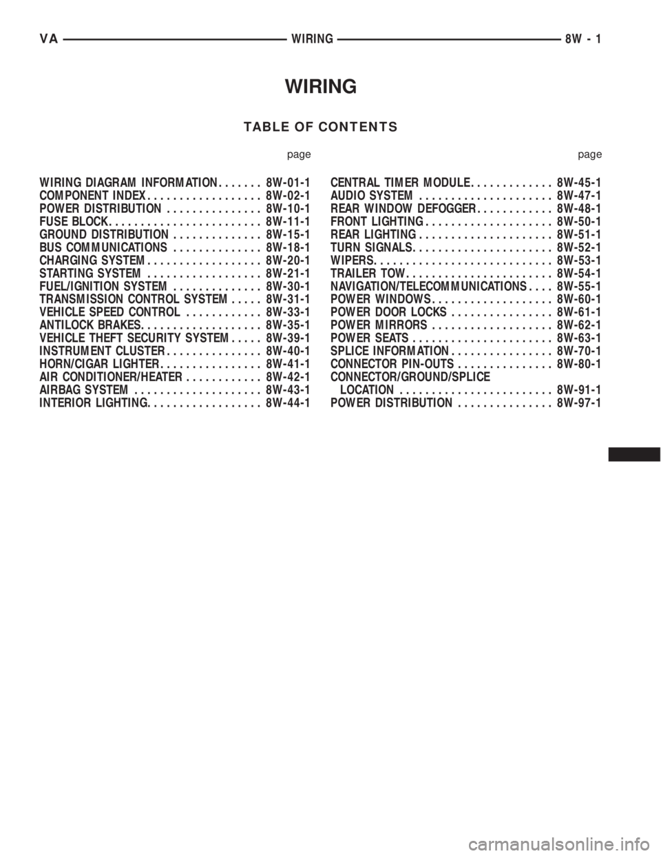
TABLE OF CONTENTS
page page
WIRING DIAGRAM INFORMATION....... 8W-01-1
COMPONENT INDEX.................. 8W-02-1
POWER DISTRIBUTION............... 8W-10-1
FUSE BLOCK........................ 8W-11-1
GROUND DISTRIBUTION.............. 8W-15-1
BUS COMMUNICATIONS.............. 8W-18-1
CHARGING SYSTEM.................. 8W-20-1
STARTING SYSTEM.................. 8W-21-1
FUEL/IGNITION SYSTEM.............. 8W-30-1
TRANSMISSION CONTROL SYSTEM..... 8W-31-1
VEHICLE SPEED CONTROL............ 8W-33-1
ANTILOCK BRAKES................... 8W-35-1
VEHICLE THEFT SECURITY SYSTEM..... 8W-39-1
INSTRUMENT CLUSTER............... 8W-40-1
HORN/CIGAR LIGHTER................ 8W-41-1
AIR CONDITIONER/HEATER............ 8W-42-1
AIRBAG SYSTEM.................... 8W-43-1
INTERIOR LIGHTING.................. 8W-44-1CENTRAL TIMER MODULE............. 8W-45-1
AUDIO SYSTEM..................... 8W-47-1
REAR WINDOW DEFOGGER............ 8W-48-1
FRONT LIGHTING.................... 8W-50-1
REAR LIGHTING..................... 8W-51-1
TURN SIGNALS...................... 8W-52-1
WIPERS............................ 8W-53-1
TRAILER TOW....................... 8W-54-1
NAVIGATION/TELECOMMUNICATIONS.... 8W-55-1
POWER WINDOWS................... 8W-60-1
POWER DOOR LOCKS................ 8W-61-1
POWER MIRRORS................... 8W-62-1
POWER SEATS...................... 8W-63-1
SPLICE INFORMATION................ 8W-70-1
CONNECTOR PIN-OUTS............... 8W-80-1
CONNECTOR/GROUND/SPLICE
LOCATION........................ 8W-91-1
POWER DISTRIBUTION............... 8W-97-1 VAWIRING 8W - 1
Page 307 of 1232
8W-01 WIRING DIAGRAM INFORMATION
TABLE OF CONTENTS
page page
WIRING DIAGRAM INFORMATION
DESCRIPTION
DESCRIPTION - HOW TO USE WIRING
DIAGRAMS...........................1
DESCRIPTION - CIRCUIT INFORMATION....5
DESCRIPTION - SECTION IDENTIFICATION
AND INFORMATION....................5
DESCRIPTION - CONNECTOR, GROUND
AND SPLICE INFORMATION..............5
WARNING
WARNINGS - GENERAL.................6
DIAGNOSIS AND TESTING - WIRING
HARNESS............................6
STANDARD PROCEDURE
STANDARD PROCEDURE -
ELECTROSTATIC DISCHARGE (ESD)
SENSITIVE DEVICES...................7
STANDARD PROCEDURE - TESTING OF
VOLTAGE POTENTIAL...................7
STANDARD PROCEDURE - TESTING FOR
CONTINUITY..........................8STANDARD PROCEDURE - TESTING FOR A
SHORT TO GROUND...................8
STANDARD PROCEDURE - TESTING FOR A
SHORT TO GROUND ON FUSES
POWERING SEVERAL LOADS............8
STANDARD PROCEDURE - TESTING FOR A
VOLTAGE DROP.......................8
CONNECTOR
REMOVAL.............................8
INSTALLATION..........................9
DIODE
REMOVAL.............................9
INSTALLATION..........................9
TERMINAL
REMOVAL.............................9
INSTALLATION.........................10
WIRE
STANDARD PROCEDURE - WIRE SPLICING . . 10
WIRING DIAGRAM
INFORMATION
DESCRIPTION
DESCRIPTION - HOW TO USE WIRING
DIAGRAMS
DaimlerChrysler Corporation wiring diagrams are
designed to provide information regarding the vehi-
cles wiring content. In order to effectively use the
wiring diagrams to diagnose and repair
DaimlerChrysler Corporation vehicles, it is important
to understand all of their features and characteris-
tics.
Diagrams are arranged such that the power (B+)
side of the circuit is placed near the top of the page,
and the ground (B-) side of the circuit is placed near
the bottom of the page (Fig. 1).
All switches, components, and modules are shown
in the at rest position with the doors closed and the
key removed from the ignition (Fig. 2).Components are shown two ways. A solid line
around a component indicates that the component is
complete. A dashed line around the component indi-
cates that the component is being shown is not com-
plete. Incomplete components have a reference
number to indicate the page where the component is
shown complete.
It is important to realize that no attempt is made
on the diagrams to represent components and wiring
as they appear on the vehicle. For example, a short
piece of wire is treated the same as a long one. In
addition, switches and other components are shown
as simply as possible, with regard to function only.
SYMBOLS
International symbols are used throughout the wir-
ing diagrams. These symbols are consistent with
those being used around the world (Fig. 3).
VA8W-01 WIRING DIAGRAM INFORMATION 8W - 01 - 1