2005 MERCEDES-BENZ SPRINTER oil capacities
[x] Cancel search: oil capacitiesPage 11 of 1232
LUBRICATION & MAINTENANCE
TABLE OF CONTENTS
page page
FLUID TYPES
DESCRIPTION
DESCRIPTION - FUEL REQUIREMENTS -
DIESEL ENGINE.......................1
DESCRIPTION - ENGINE COOLANT........1
DESCRIPTION - HOAT COOLANT..........2
DESCRIPTION - AXLE...................3
DESCRIPTION - BRAKE FLUID............3
DESCRIPTION - POWER STEERING FLUID . . 3
DESCRIPTION - ENGINE OIL - DIESEL
ENGINES............................3
DESCRIPTION - AUTOMATIC
TRANSMISSION FLUID - NAG1............4
OPERATION - AUTOMATIC TRANSMISSION
FLUID...............................4
FLUID CAPACITIES
SPECIFICATIONS - FLUID CAPACITIES.......4FLUID FILL/CHECK LOCATIONS
INSPECTION - FLUID FILL/CHECK
LOCATIONS..........................4
PARTS & LUBRICANT RECOMMENDATION
STANDARD PROCEDURE - PARTS &
LUBRICANT RECOMMENDATIONS.........5
HOISTING
STANDARD PROCEDURE - HOISTING........5
JUMP STARTING
STANDARD PROCEDURE - JUMP STARTING . . 6
TOWING
STANDARD PROCEDURE - TOWING.........6
MAINTENANCE SCHEDULES
DESCRIPTION..........................7
INTERNATIONAL SYMBOLS
DESCRIPTION..........................9
FLUID TYPES
DESCRIPTION
DESCRIPTION - FUEL REQUIREMENTS -
DIESEL ENGINE
DESCRIPTION
WARNING: Do not use alcohol or gasoline as a fuel
blending agent. They can be unstable under certain
conditions and hazardous or explosive when mixed
with diesel fuel.
Use good quality diesel fuel from a reputable sup-
plier in your Dodge truck. For most year-round ser-
vice, number 2 diesel fuel meeting ASTM
specification D-975 will provide good performance. If
the vehicle is exposed to extreme cold (below 0ÉF/-
18ÉC), or is required to operate at colder-than-normal
conditions for prolonged periods, use climatized No. 2
diesel fuel or dilute the No. 2 diesel fuel with 50%
No. 1 diesel fuel. This will provide better protection
from fuel gelling or wax-plugging of the fuel filters.
Diesel fuel is seldom completely free of water. To
prevent fuel system trouble, including fuel line freez-
ing in winter, drain the accumulated water from the
fuel/water separator using the fuel/water separator
drain provided. If you buy good-quality fuel and fol-low the cold-weather advice above, fuel conditioners
should not be required in your vehicle. If available in
your area, a high cetane ªpremiumº diesel fuel may
offer improved cold starting and warm-up perfor-
mance.
DESCRIPTION - ENGINE COOLANT
ETHYLENE-GLYCOL MIXTURES
CAUTION: Richer antifreeze mixtures cannot be
measured with normal field equipment and can
cause problems associated with 100 percent ethyl-
ene-glycol.
The required ethylene-glycol (antifreeze) and water
mixture depends upon the climate and vehicle oper-
ating conditions. The recommended mixture of 50/50
ethylene-glycol and water will provide protection
against freezing to -37É C (-34É F). The antifreeze
concentrationmust alwaysbe a minimum of 44 per-
cent, year-round in all climates.If percentage is
lower than 44 percent, engine parts may be
eroded by cavitation, and cooling system com-
ponents may be severely damaged by corrosion.
Maximum protection against freezing is provided
with a 68 percent antifreeze concentration, which
prevents freezing down to -67.7É C (-90É F). A higher
percentage will freeze at a warmer temperature.
Also, a higher percentage of antifreeze can cause the
VALUBRICATION & MAINTENANCE 0 - 1
Page 14 of 1232
Full synthetic oils, such as Mobilt1 0W-40, is
required if the ASSYST Oil Service Reminder is fol-
lowed. Use of a lower quality oil on this service
schedule may cause severe engine damage.
DESCRIPTION - AUTOMATIC TRANSMISSION
FLUID - NAG1
NOTE: Refer to Service Procedures in this group for
fluid level checking procedures.
Shellt3403 Automatic Transmission Fluid is the
recommended fluid for the NAG1 DaimlerChrysler
automatic transmission.
Dexron II fluid IS NOT recommended. Clutch
chatter can result from the use of improper
fluid.
MopartATF+4, Automatic Transmission Fluid, or
other fluids meeting MS-9602, may be used if Shellt
3403 Automatic Transmission Fluid is not available.
Shellt3403 Automatic Transmission Fluid when
new is red in color. The ATF is dyed red so it can be
identified from other fluids used in the vehicle such
as engine oil or antifreeze. The red color is not per-
manent and is not an indicator of fluid condition. As
the vehicle is driven, the ATF will begin to look
darker in color and may eventually become brown.
This is normal.
FLUID ADDITIVES
DaimlerChrysler strongly recommends against the
addition of any fluids to the transmission, other than
those automatic transmission fluids listed above.
Exceptions to this policy are the use of special dyes
to aid in detecting fluid leaks.
Various ªspecialº additives and supplements exist
that claim to improve shift feel and/or quality. These
additives and others also claim to improve converter
clutch operation and inhibit overheating, oxidation,
varnish, and sludge. These claims have not been sup-
ported to the satisfaction of DaimlerChrysler and
these additivesmust not be used.The use of trans-
mission ªsealersº should also be avoided, since they
may adversely affect the integrity of transmission
seals.
OPERATION - AUTOMATIC TRANSMISSION
FLUID
The automatic transmission fluid is selected based
upon several qualities. The fluid must provide a high
level of protection for the internal components by
providing a lubricating film between adjacent metal
components. The fluid must also be thermally stable
so that it can maintain a consistent viscosity through
a large temperature range. If the viscosity stays con-
stant through the temperature range of operation,transmission operation and shift feel will remain con-
sistent. Transmission fluid must also be a good con-
ductor of heat. The fluid must absorb heat from the
internal transmission components and transfer that
heat to the transmission case.
FLUID CAPACITIES
SPECIFICATIONS - FLUID CAPACITIES
DESCRIPTION SPECIFICATION
ENGINE COOLANT
10 Liters 10.5 Quarts
ENGINE OIL
9.0L with Filter
Replacement9.5 Quarts with Filter
Replacement
AUTOMATIC TRANSMISSION
Service Fill - NAG1 5.0 L (10.6 pts.)
O-haul Fill - NAG1 7.7 L (16.3 pts.)
Dry fill capacity Depending on type and size of
internal cooler, length and inside diameter of cooler
lines, or use of an auxiliary cooler, these figures may
vary. (Refer to appropriate 21 - TRANSMISSION/
AUTOMATIC/FLUID - STANDARD PROCEDURE).
REAR AXLE .03L (1 oz.)
8 1/2 1.8 L (4.0 pts.)
FUEL TANK
Primary 100 L (26.4 gal.)*
Reserve 10.5 L (2.8 gal.)*
*Nominal refill capacities are shown. A variation may
be observed from vehicle to vehicle due to
manufacturing tolerance and refill procedure
POWER STEERING SYSTEM
Power steering fluid capacities are dependent on
engine/chassis options as well as steering gear/cooler
options. Depending on type and size of internal
cooler, length and inside diameter of cooler lines, or
use of an auxiliary cooler, these capacities may vary.
Refer to 19, Steering for proper fill and bleed
procedures.
FLUID FILL/CHECK
LOCATIONS
INSPECTION - FLUID FILL/CHECK LOCATIONS
The fluid fill/check locations and lubrication points
are located in each applicable group.
0 - 4 LUBRICATION & MAINTENANCEVA
FLUID TYPES (Continued)
Page 159 of 1232
INSTALLATION
(1) Raise and support vehicle.
(2) Position starter motor to transmission housing.
(3) Install 2 mounting bolts. Refer to Torque Spec-
ifications.
(4) Lower vehicle.
(5) Connect battery cable and solenoid wiring to
solenoid (2 nuts). Refer to Torque Specifications.
(6) Position wiring harness trough and install
retaining bolt.
(7) Install new nylon tie-wraps to wiring trough.
(8) Connect negative battery cable.
STARTER MOTOR RELAY
DESCRIPTION
The starter relay is an electromechanical device
that switches battery current to the pull-in coil of the
starter solenoid when ignition switch is turned to
Start position. The starter relay is located in the
Fuse/Relay Block. The Fuse/Relay Block is located
under, and to the left side of the drivers seat. See
Fuse/Relay Block cover for relay identification and
location.
The starter relay is an International Standards
Organization (ISO) relay. Relays conforming to ISO
specifications have common physical dimensions, cur-
rent capacities, terminal patterns, and terminal func-
tions.
The starter relay cannot be repaired or adjusted
and, if faulty or damaged, it must be replaced.
REMOVAL
The starter relay is located in the Fuse/Relay
Block. The Fuse/Relay Block is located under, and to
the left side of the drivers seat. See Fuse/Relay Block
cover for relay identification and location, or refer to
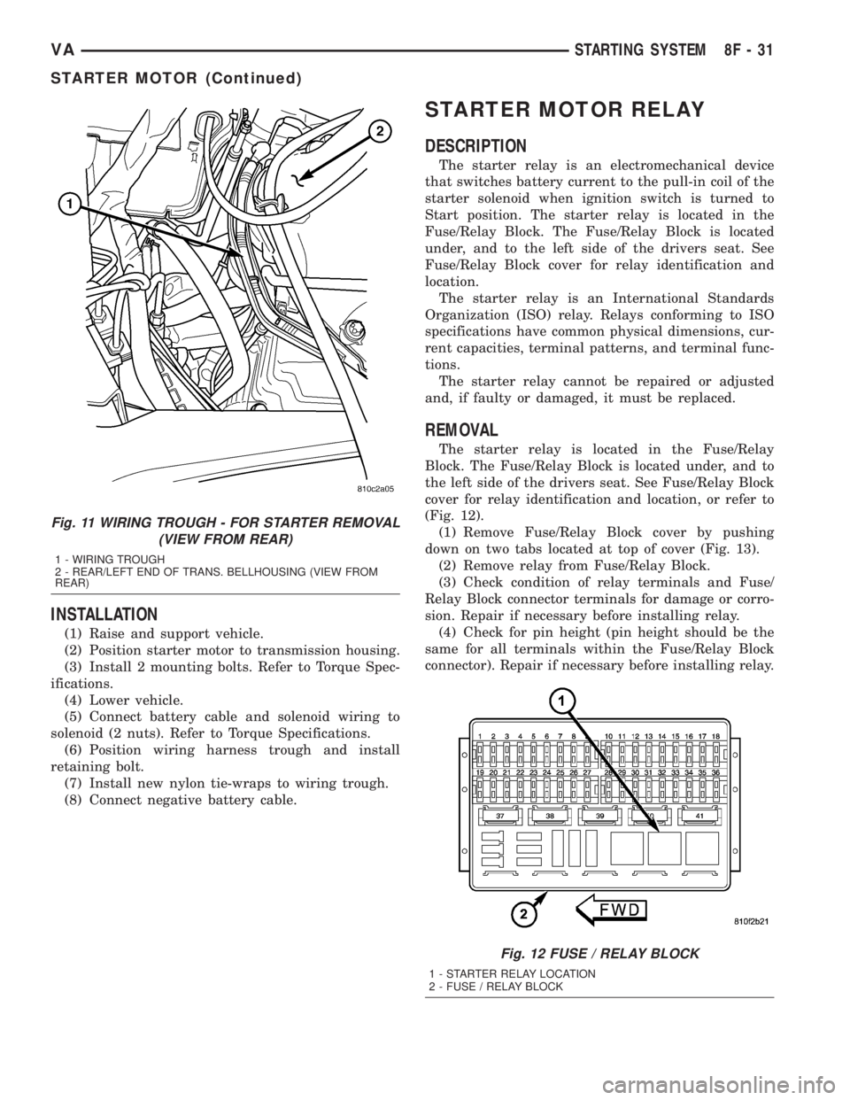
(Fig. 12).
(1) Remove Fuse/Relay Block cover by pushing
down on two tabs located at top of cover (Fig. 13).
(2) Remove relay from Fuse/Relay Block.
(3) Check condition of relay terminals and Fuse/
Relay Block connector terminals for damage or corro-
sion. Repair if necessary before installing relay.
(4) Check for pin height (pin height should be the
same for all terminals within the Fuse/Relay Block
connector). Repair if necessary before installing relay.
Fig. 11 WIRING TROUGH - FOR STARTER REMOVAL
(VIEW FROM REAR)
1 - WIRING TROUGH
2 - REAR/LEFT END OF TRANS. BELLHOUSING (VIEW FROM
REAR)
Fig. 12 FUSE / RELAY BLOCK
1 - STARTER RELAY LOCATION
2 - FUSE / RELAY BLOCK
VASTARTING SYSTEM 8F - 31
STARTER MOTOR (Continued)
Page 164 of 1232
HEATED SEAT RELAY
DESCRIPTION
The heated seat relay is an electromechanical
device that switches 12v battery current to the
heated seat elements when the relay control coil is
energized. The heated seat relay is located in the
Fuse Block, under the drivers seat. The heated seat
relay is a International Standards Organization
(ISO) relay. Relays conforming to the ISO specifica-
tions have common physical dimensions, current
capacities, terminal patterns, and terminal functions.
The heated seat relay cannot be repaired or
adjusted and, if faulty or damaged, it must be
replaced.
OPERATION
The ISO relay consists of an electromagnetic coil, a
resistor or diode, and three (two fixed and one mov-
able) electrical contacts. The movable (common feed)
relay contact is held against one of the fixed contacts
(normally closed) by spring pressure. When the elec-
tromagnetic coil is energized, it draws the movable
contact away from the normally closed fixed contact,
and holds it against the other (normally open) fixed
contact. When the electromagnetic coil is de-ener-
gized, spring pressure returns the movable contact to
the normally closed position. The resistor or diode is
connected in parallel with the electromagnetic coil in
the relay, and helps to dissipate voltage spikes that
are produced when the coil is de-energized.
DIAGNOSIS AND TESTING - HEATED SEAT
RELAY
The heated seat relay is located in the Fuse Block,
under the drivers seat. Refer toWiringfor the loca-
tion of complete heated seat system wiring diagrams.
(1) Remove the heated seat relay from the fuse
block.
(2) A relay in the de-energized position should
have continuity between terminals 87A and 30, and
no continuity between terminals 87 and 30. If OK, go
to Step 3. If not OK, replace the faulty relay.
(3) Resistance between terminals 85 and 86 (elec-
tromagnet) should be 75 5 ohms. If OK, go to Step
4. If not OK, replace the faulty relay.
(4) Connect a battery to terminals 85 and 86.
There should now be continuity between terminals
30 and 87, and no continuity between terminals 87A
and 30. If OK, check the relay supply circuits. If not
OK, replace the faulty relay.
REMOVAL
(1) Disconnect and isolate the battery negative
cable.
(2) The heated seat relay is located in the fuse
block, under the drivers seat. Refer to wiring for
detailed location.
(3) Grasp the heated seat relay firmly and pull it
straight out from the fuse block. A slight rocking
motion will aid in removal.
INSTALLATION
(1) Grasp the heated seat relay firmly and push it
straight in the fuse block.
(2) Reconnect the battery negative cable.
HEATED SEAT SENSOR
DESCRIPTION
The heated seat temperature sensor is a Negative
Temperature Coefficient (NTC) thermistor. One tem-
perature sensor is used for each seat. The sensor is
located in the seat cushion heating element for all
models.
The heated seat sensor cannot be adjusted or
repaired and if it is found to be faulty, the complete
heated seat element must be replaced.
DIAGNOSIS AND TESTING - HEATED SEAT
SENSOR
For complete circuit diagrams, refer toWiring.
NOTE: Any resistance values (ohmsV) given in the
following text are supplied using the automatic
range generated by a FLUKETautomotive meter. If
another type of measuring device is used the val-
ues generated may not be the same as the results
shown here, or may have to be converted to the
range used here.
(1) Backprobe the heated seat relay wire harness
connector, do not disconnect. Using an voltmeter,
check the voltage of the seat temperature sensor
input cavity of the heated seat relay wire harness
connector. The seat sensor input voltage should be
between 1.7 volts and 3.0 volts with the system ON.
If OK, sensor is OK at this time. If not OK, replace
the faulty seat cushion heating element and sensor
assembly.
8G - 4 HEATED SYSTEMSVA
Page 736 of 1232
OPERATION
The power outlet base or receptacle shell is con-
nected to ground, and an insulated contact in the
bottom of the shell is connected to battery current.
The power outlet receives battery voltage from a fuse
in the fuse block at all times.
DIAGNOSIS AND TESTING - POWER OUTLET
(1) Check for battery voltage at the fused B(+) fuse
in the fuse block. If OK, go to Step 2. If not OK,
repair the open fused B(+) circuit to the battery as
required.
(2) Check for continuity between the inside cir-
cumference of the power outlet receptacle and a good
ground. There should be continuity. If OK, go to Step
3. If not OK, go to Step 4.
(3) Check for battery voltage at the insulated con-
tact located at the back of the power outlet recepta-
cle. If not OK, go to Step 4.
(4) Disconnect and isolate the battery negative
cable. Check for continuity between the ground cir-
cuit cavity of the power outlet wire harness connector
and a good ground. There should be continuity. If
OK, go to Step 5. If not OK, repair the open ground
circuit to ground as required.
(5) Connect the battery negative cable. Check for
battery voltage at the fused B(+) circuit cavity of the
power outlet wire harness connector. If OK, replace
the faulty power outlet receptacle. If not OK, repair
the open fused B(+) circuit to the fuse in the fuse
block as required.
REMOVAL
(1) Disconnect and isolate the battery negative
cable.
(2) Pull the cigar lighter knob and element out of
the cigar lighter receptacle base, or unsnap the pro-
tective cap from the power outlet receptacle base.
(3) Look inside the cigar lighter or power outlet
receptacle base and note the position of the rectangu-
lar retaining bosses of the mount that secures the
receptacle base to the instrument panel.
(4) Insert a pair of external snap ring pliers into
the cigar lighter or power outlet receptacle base and
engage the tips of the pliers with the retaining
bosses of the mount.
(5) Squeeze the pliers to disengage the mount
retaining bosses from the receptacle base and, using
a gentle rocking motion, pull the pliers and the
receptacle base out of the mount.
(6) Disconnect the instrument panel wire harness
connector from the connector receptacle of the cigar
lighter or the power outlet receptacle base.
(7) Remove the cigar lighter or power outlet mount
from the instrument panel.
INSTALLATION
(1) Install the cigar lighter or power outlet mount
into the instrument panel.
(2) Reconnect the instrument panel wire harness
connector to the connector receptacle of the cigar
lighter or the power outlet receptacle base.
(3) Align the splines on the outside of the cigar
lighter or power outlet receptacle base connector
receptacle with the grooves on the inside of the
mount.
(4) Press firmly on the cigar lighter or power out-
let receptacle base until the retaining bosses of the
mount are fully engaged in their receptacles.
(5) Install the cigar lighter knob and element into
the cigar lighter receptacle base.
(6) Reconnect the battery negative cable.
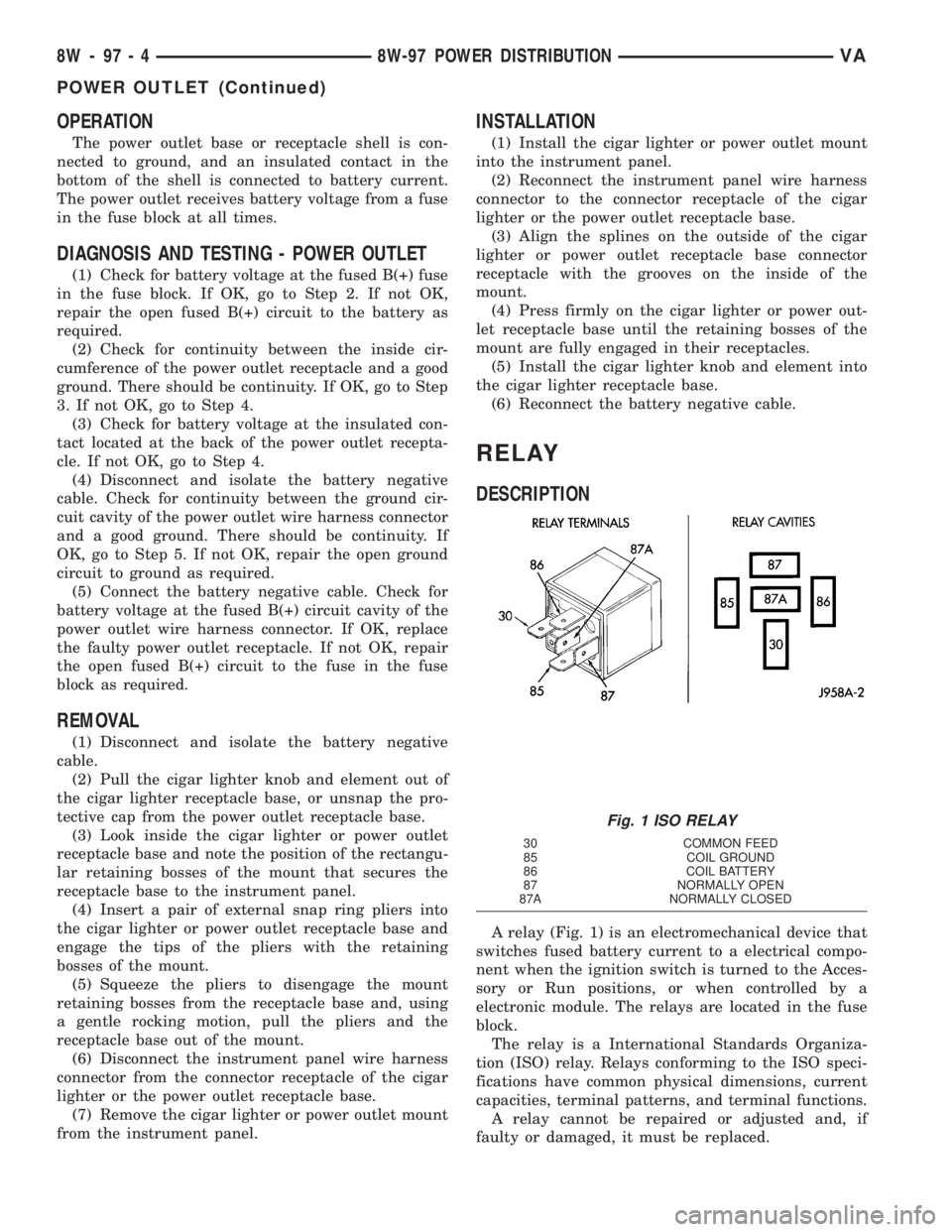
RELAY
DESCRIPTION
A relay (Fig. 1) is an electromechanical device that
switches fused battery current to a electrical compo-
nent when the ignition switch is turned to the Acces-
sory or Run positions, or when controlled by a
electronic module. The relays are located in the fuse
block.
The relay is a International Standards Organiza-
tion (ISO) relay. Relays conforming to the ISO speci-
fications have common physical dimensions, current
capacities, terminal patterns, and terminal functions.
A relay cannot be repaired or adjusted and, if
faulty or damaged, it must be replaced.
Fig. 1 ISO RELAY
30 COMMON FEED
85 COIL GROUND
86 COIL BATTERY
87 NORMALLY OPEN
87A NORMALLY CLOSED
8W - 97 - 4 8W-97 POWER DISTRIBUTIONVA
POWER OUTLET (Continued)
Page 1193 of 1232
REFRIGERANT
DESCRIPTION
The refrigerant used in this air conditioning sys-
tem is a HydroFluoroCarbon (HFC), type R-134a.
Unlike R-12, which is a ChloroFluoroCarbon (CFC),
R-134a refrigerant does not contain ozone-depleting
chlorine. R-134a refrigerant is a non-toxic, non-flam-
mable, clear, and colorless liquefied gas.
Even though R-134a does not contain chlorine, it
must be reclaimed and recycled just like CFC-type
refrigerants. This is because R-134a is a greenhouse
gas and can contribute to global warming.
OPERATION
R-134a refrigerant is not compatible with R-12
refrigerant in an air conditioning system. Even a
small amount of R-12 added to an R-134a refrigerant
system will cause compressor failure, refrigerant oil
sludge or poor air conditioning system performance.
In addition, the PolyAlkylene Glycol (PAG) synthetic
refrigerant oils used in an R-134a refrigerant system
are not compatible with the mineral-based refriger-
ant oils used in an R-12 refrigerant system.
R-134a refrigerant system service ports, service
tool couplers and refrigerant dispensing bottles have
all been designed with unique fittings to ensure that
an R-134a system is not accidentally contaminated
with the wrong refrigerant (R-12). There are also
labels posted in the engine compartment of the vehi-
cle and on the compressor identifying to service tech-
nicians that the air conditioning system is equipped
with R-134a.
REFRIGERANT OIL
DESCRIPTION
The refrigerant oil used in R-134a refrigerant sys-
tems is a synthetic-based, PolyAlkylene Glycol (PAG),
wax-free lubricant. Mineral-based R-12 refrigerant
oils are not compatible with PAG oils, and should
never be introduced to an R-134a refrigerant system.
There are different PAG oils available, and each
contains a different additive package. The 10PA17
compressor used in this vehicle is designed to use an
ND8 PAG refrigerant oil. Use only refrigerant oil of
this same type to service the refrigerant system.
OPERATION
After performing any refrigerant recovery or recy-
cling operation, always replenish the refrigerant sys-
tem with the same amount of the recommended
refrigerant oil as was removed. Too little refrigerant
oil can cause compressor damage, and too much can
reduce air conditioning system performance.
PAG refrigerant oil is much more hygroscopic than
mineral oil, and will absorb any moisture it comes
into contact with, even moisture in the air. The PAG
oil container should always be kept tightly capped
until it is ready to be used. After use, recap the oil
container immediately to prevent moisture contami-
nation.
STANDARD PROCEDURE - REFRIGERANT OIL
LEVEL
When an air conditioning system is assembled at
the factory, all components except the compressor are
refrigerant oil free. After the refrigerant system has
been charged and operated, the refrigerant oil in the
compressor is dispersed throughout the refrigerant
system. The receiver-drier, evaporator, condenser,
and compressor will each retain a significant amount
of the needed refrigerant oil.
It is important to have the correct amount of oil in
the refrigerant system. This ensures proper lubrica-
tion of the compressor. Too little oil will result in
damage to the compressor. Too much oil will reduce
the cooling capacity of the air conditioning system.
It will not be necessary to check the oil level in the
compressor or to add oil, unless there has been an oil
loss. An oil loss may occur due to a rupture or leak
from a refrigerant line, a connector fitting, a compo-
nent, or a component seal. If a leak occurs, add 30
milliliters (1 fluid ounce) of refrigerant oil to the
refrigerant system after the repair has been made.
Refrigerant oil loss will be evident at the leak point
by the presence of a wet, shiny surface around the
leak.
Refrigerant oil must be added when a receiver/
drier, evaporator coil, or condenser are replaced. See
the Refrigerant Oil Capacities chart. When a com-
pressor is replaced, the refrigerant oil must be
drained from the old compressor and measured.
Drain all of the refrigerant oil from the new compres-
sor, then fill the new compressor with the same
amount of refrigerant oil that was drained out of the
old compressor.
VAPLUMBING 24 - 65
Page 1194 of 1232
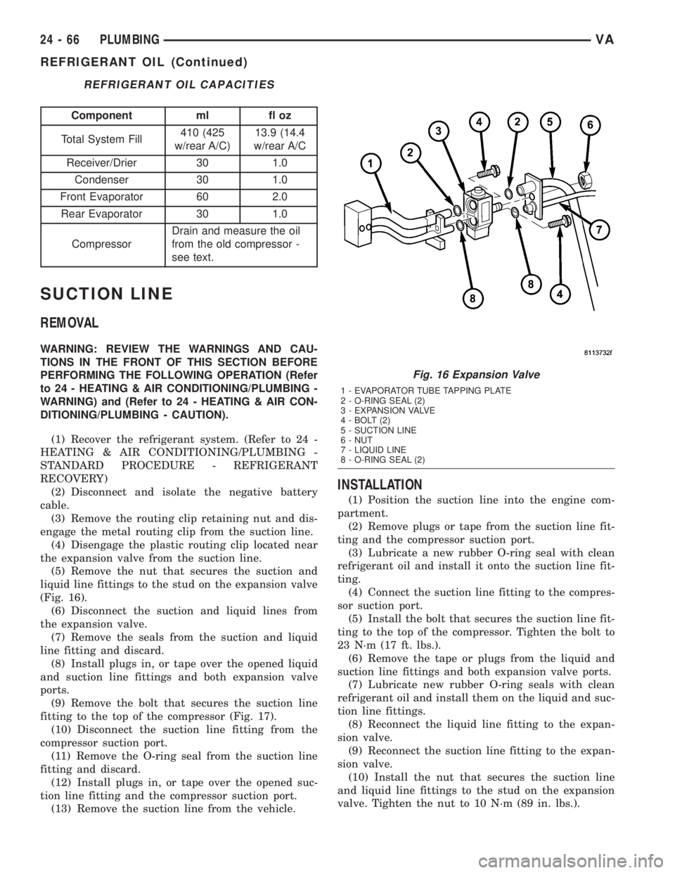
REFRIGERANT OIL CAPACITIES
Component ml fl oz
Total System Fill410 (425
w/rear A/C)13.9 (14.4
w/rear A/C
Receiver/Drier 30 1.0
Condenser 30 1.0
Front Evaporator 60 2.0
Rear Evaporator 30 1.0
CompressorDrain and measure the oil
from the old compressor -
see text.
SUCTION LINE
REMOVAL
WARNING: REVIEW THE WARNINGS AND CAU-
TIONS IN THE FRONT OF THIS SECTION BEFORE
PERFORMING THE FOLLOWING OPERATION (Refer
to 24 - HEATING & AIR CONDITIONING/PLUMBING -
WARNING) and (Refer to 24 - HEATING & AIR CON-
DITIONING/PLUMBING - CAUTION).
(1) Recover the refrigerant system. (Refer to 24 -
HEATING & AIR CONDITIONING/PLUMBING -
STANDARD PROCEDURE - REFRIGERANT
RECOVERY)
(2) Disconnect and isolate the negative battery
cable.
(3) Remove the routing clip retaining nut and dis-
engage the metal routing clip from the suction line.
(4) Disengage the plastic routing clip located near
the expansion valve from the suction line.
(5) Remove the nut that secures the suction and
liquid line fittings to the stud on the expansion valve
(Fig. 16).
(6) Disconnect the suction and liquid lines from
the expansion valve.
(7) Remove the seals from the suction and liquid
line fitting and discard.
(8) Install plugs in, or tape over the opened liquid
and suction line fittings and both expansion valve
ports.
(9) Remove the bolt that secures the suction line
fitting to the top of the compressor (Fig. 17).
(10) Disconnect the suction line fitting from the
compressor suction port.
(11) Remove the O-ring seal from the suction line
fitting and discard.
(12) Install plugs in, or tape over the opened suc-
tion line fitting and the compressor suction port.
(13) Remove the suction line from the vehicle.
INSTALLATION
(1) Position the suction line into the engine com-
partment.
(2) Remove plugs or tape from the suction line fit-
ting and the compressor suction port.
(3) Lubricate a new rubber O-ring seal with clean
refrigerant oil and install it onto the suction line fit-
ting.
(4) Connect the suction line fitting to the compres-
sor suction port.
(5) Install the bolt that secures the suction line fit-
ting to the top of the compressor. Tighten the bolt to
23 N´m (17 ft. lbs.).
(6) Remove the tape or plugs from the liquid and
suction line fittings and both expansion valve ports.
(7) Lubricate new rubber O-ring seals with clean
refrigerant oil and install them on the liquid and suc-
tion line fittings.
(8) Reconnect the liquid line fitting to the expan-
sion valve.
(9) Reconnect the suction line fitting to the expan-
sion valve.
(10) Install the nut that secures the suction line
and liquid line fittings to the stud on the expansion
valve. Tighten the nut to 10 N´m (89 in. lbs.).
Fig. 16 Expansion Valve
1 - EVAPORATOR TUBE TAPPING PLATE
2 - O-RING SEAL (2)
3 - EXPANSION VALVE
4 - BOLT (2)
5 - SUCTION LINE
6 - NUT
7 - LIQUID LINE
8 - O-RING SEAL (2)
24 - 66 PLUMBINGVA
REFRIGERANT OIL (Continued)
Page 1213 of 1232
BRAKE/PARK BRAKE INDICATOR -
OPERATION.........................8J-12
BRAKE/PARK LAMP BULB -
INSTALLATION........................8L-7
BRAKE/PARK LAMP BULB - REMOVAL.....8L-7
BRAKES, SPECIAL TOOLS................5-7
BREAKER - DESCRIPTION, CIRCUIT....8W-97-2
BREAKER - DIAGNOSIS AND TESTING,
CIRCUIT.........................8W-97-2
BREAKER - OPERATION, CIRCUIT.....8W-97-2
BREAK-IN - STANDARD PROCEDURE,
COMPRESSOR CLUTCH................24-9
BUCKLE - INSTALLATION, FRONT SEAT
BELT ..............................8O-23
BUCKLE - REMOVAL, FRONT SEAT BELT . . 8O-22
BULB - INSTALLATION, BACKUP LAMP....8L-6
BULB - INSTALLATION, BRAKE/PARK
LAMP...............................8L-7
BULB - INSTALLATION, CARGO/DOME
LAMP..............................8L-27
BULB - INSTALLATION, CENTER HIGH
MOUNTED STOP LAMP.................8L-7
BULB - INSTALLATION, CLEARANCE
LAMP...............................8L-8
BULB - INSTALLATION, DOME
LAMP/INTRUSION SENSOR.............8L-30
BULB - INSTALLATION, DOME/READING
LAMP..............................8L-29
BULB - INSTALLATION, ENTRY/EXIT
LAMP..............................8L-32
BULB - INSTALLATION, FOG LAMP.......8L-10
BULB - INSTALLATION, FRONT POSITION
LAMP..............................8L-14
BULB - INSTALLATION, FRONT
TURN/PARK/SIDE MARKER LAMP.......8L-15
BULB - INSTALLATION, HIGH BEAM
HEADLAMP.........................8L-17
BULB - INSTALLATION, LICENSE PLATE
LAMP..............................8L-18
BULB - INSTALLATION, LOW BEAM
HEADLAMP.........................8L-19
BULB - INSTALLATION, REAR SIDE
MARKER LAMP......................8L-21
BULB - INSTALLATION, REAR TURN
LAMP..............................8L-22
BULB - INSTALLATION, REPEATER LAMP . . 8L-22
BULB - REMOVAL, BACKUP LAMP........8L-5
BULB - REMOVAL, BRAKE/PARK LAMP....8L-7
BULB - REMOVAL, CARGO/DOME LAMP . . 8L-27
BULB - REMOVAL, CENTER HIGH
MOUNTED STOP LAMP.................8L-7
BULB - REMOVAL, CLEARANCE LAMP.....8L-8
BULB - REMOVAL, DOME LAMP/
INTRUSION SENSOR..................8L-30
BULB - REMOVAL, DOME/READING
LAMP..............................8L-29
BULB - REMOVAL, ENTRY/EXIT LAMP....8L-31
BULB - REMOVAL, FOG LAMP..........8L-10
BULB - REMOVAL, FRONT POSITION
LAMP..............................8L-14
BULB - REMOVAL, FRONT TURN/PARK/
SIDE MARKER LAMP.................8L-14
BULB - REMOVAL, HIGH BEAM
HEADLAMP.........................8L-17
BULB - REMOVAL, LICENSE PLATE
LAMP..............................8L-17
BULB - REMOVAL, LOW BEAM
HEADLAMP.........................8L-18
BULB - REMOVAL, REAR SIDE MARKER
LAMP..............................8L-21
BULB - REMOVAL, REAR TURN LAMP....8L-21
BULB - REMOVAL, REPEATER LAMP.....8L-22
BULKHEAD - INSTALLATION............8L-29
BULKHEAD - REMOVAL................8L-28
BULKHEAD TRIM PANEL -
INSTALLATION.......................23-69
BULKHEAD TRIM PANEL -
INSTALLATION, BACKLITE..............23-81
BULKHEAD TRIM PANEL - REMOVAL.....23-69
BULKHEAD TRIM PANEL - REMOVAL,
BACKLITE..........................23-81
BUMPER - STEP - INSTALLATION, REAR
. . . 13-3
BUMPER - STEP - REMOVAL, REAR
.......13-3
BUMPER - STEPS - INSTALLATION,
FRONT
..............................13-2
BUMPER - STEPS - REMOVAL, FRONT
.....13-2
BURNT FLUID - DIAGNOSIS AND
TESTING, CAUSES OF
................21-102BUSHINGS - INSTALLATION..............2-3
BUSHINGS - REMOVAL..................2-3
BUZZ, SQUEAK & RATTLE - STANDARD
PROCEDURE........................23-10
CABIN HEATER - DESCRIPTION.........24-72
CABIN HEATER - OPERATION...........24-72
CABLE - DESCRIPTION.................8P-3
CABLE - DIAGNOSIS AND TESTING,
GEARSHIFT........................21-109
CABLE - INSTALLATION, ANTENNA BODY . . 8A-1
CABLE - INSTALLATION, GEARSHIFT....21-109
CABLE - INSTALLATION, INSTRUMENT
PANEL ANTENNA......................8A-2
CABLE - INSTALLATION, LATCH RELEASE . 23-51
CABLE - INSTALLATION, PARK LOCK....21-126
CABLE - REMOVAL, ANTENNA BODY......8A-1
CABLE - REMOVAL, GEARSHIFT........21-109
CABLE - REMOVAL, INSTRUMENT PANEL
ANTENNA...........................8A-1
CABLE - REMOVAL, LATCH RELEASE.....23-51
CABLE - REMOVAL, PARK LOCK........21-125
CABLE TENSIONER - INSTALLATION......5-23
CABLE TENSIONER - REMOVAL..........5-23
CABLES - ADJUSTMENT, PARKING
BRAKE..............................5-25
CABLES - DESCRIPTION, BATTERY.......8F-14
CABLES - DIAGNOSIS AND TESTING,
BATTERY...........................8F-14
CABLES - INSTALLATION, BATTERY......8F-16
CABLES - INSTALLATION, MODE DOOR . . . 24-19
CABLES - OPERATION, BATTERY........8F-14
CABLES - REMOVAL, BATTERY..........8F-16
CABLES - REMOVAL, MODE DOOR.......24-19
CAMSHAFT POSITION - STANDARD
PROCEDURE, CHECKING................9-27
CAMSHAFT POSITION SENSOR -
DESCRIPTION.......................14-19
CAMSHAFT POSITION SENSOR -
INSTALLATION.......................14-19
CAMSHAFT POSITION SENSOR -
OPERATION.........................14-19
CAMSHAFT POSITION SENSOR -
REMOVAL..........................14-19
CAMSHAFT(S) - INSTALLATION..........9-29
CAMSHAFT(S) - REMOVAL..............9-28
CAP - DESCRIPTION, RADIATOR
PRESSURE..........................7-18
CAP - DIAGNOSIS AND TESTING,
RADIATOR PRESSURE.................7-19
CAP - OPERATION, RADIATOR
PRESSURE..........................7-18
CAPACITIES - SPECIFICATIONS, FLUID......0-4
CAPACITY, SPECIFICATIONS - CHARGE . . . 24-49
CARGO/DOME LAMP BULB -
INSTALLATION.......................8L-27
CARGO/DOME LAMP BULB - REMOVAL . . . 8L-27
CARGO/DOME LAMP UNIT -
INSTALLATION.......................8L-28
CARGO/DOME LAMP UNIT - REMOVAL . . . 8L-28
CARPETS AND FLOOR MATS -
INSTALLATION.......................23-70
CARPETS AND FLOOR MATS - REMOVAL . 23-69
CARRIER - INSTALLATION, SPARE TIRE . . . 22-10
CARRIER - REMOVAL, SPARE TIRE......22-10
CATALYTIC CONVERTER - INSTALLATION . . . 11-3
CATALYTIC CONVERTER - REMOVAL......11-3
CAUSES OF BURNT FLUID - DIAGNOSIS
AND TESTING
......................21-102
CAUTION - CAUTION
..................24-45
CAUTION - REFRIGERANT HOSES/LINES/
TUBES PRECAUTIONS
.................24-45
CAUTION, CAUTION
...................24-45
CAUTION, INTERIOR
..................23-67
CENTER - DESCRIPTION, POWER
DISTRIBUTION
....................8W-97-3
CENTER - OPERATION, POWER
DISTRIBUTION
....................8W-97-3
CENTER BEARING - INSTALLATION
........3-9
CENTER BEARING - REMOVAL
............3-8
CENTER BEZEL - INSTALLATION,
INSTRUMENT PANEL
..................23-55
CENTER BEZEL - REMOVAL,
INSTRUMENT PANEL
..................23-55
CENTER HIGH MOUNTED STOP LAMP
BULB - INSTALLATION
.................8L-7
CENTER HIGH MOUNTED STOP LAMP
BULB - REMOVAL
.....................8L-7CENTER HIGH MOUNTED STOP LAMP
UN - INSTALLATION...................8L-8
CENTER HIGH MOUNTED STOP LAMP
UN - REMOVAL.......................8L-8
CENTER ROLLER ARM - INSTALLATION . . . 23-38
CENTER ROLLER ARM - REMOVAL......23-37
CENTER TRACK - INSTALLATION........23-39
CENTER TRACK - REMOVAL............23-38
CENTERING - STANDARD PROCEDURE,
CLOCKSPRING......................8O-13
CENTRAL TIMER MODULE -
DESCRIPTION........................8E-1
CENTRAL TIMER MODULE - DIAGNOSIS
AND TESTING........................8E-2
CENTRAL TIMER MODULE -
INSTALLATION........................8E-2
CENTRAL TIMER MODULE - OPERATION . . . 8E-2
CENTRAL TIMER MODULE - REMOVAL....8E-2
CHAIN - INSTALLATION, OIL PUMP.......9-54
CHAIN - INSTALLATION, TIMING.........9-67
CHAIN - REMOVAL, OIL PUMP...........9-53
CHAIN - REMOVAL, TIMING.............9-63
CHAIN COVER - INSTALLATION, TIMING . . . 9-60
CHAIN COVER - REMOVAL, TIMING.......9-59
CHAIN TENSIONER - INSTALLATION,
TIMING.............................9-71
CHAIN TENSIONER - REMOVAL, TIMING . . . 9-70
CHAIN TENSIONING RAIL -
INSTALLATION, TIMING.................9-66
CHAIN TENSIONING RAIL - REMOVAL,
TIMING.............................9-63
CHARGE - STANDARD PROCEDURE,
REFRIGERANT SYSTEM...............24-48
CHARGE AIR COOLER AND PLUMBING -
CLEANING...........................11-5
CHARGE AIR COOLER AND PLUMBING -
DESCRIPTION........................11-4
CHARGE AIR COOLER AND PLUMBING -
INSPECTION.........................11-5
CHARGE AIR COOLER AND PLUMBING -
INSTALLATION........................11-5
CHARGE AIR COOLER AND PLUMBING -
OPERATION..........................11-4
CHARGE AIR COOLER AND PLUMBING -
REMOVAL...........................11-5
CHARGE AIR COOLER SYSTEM - LEAKS
- DIAGNOSIS AND TESTING.............11-4
CHARGE CAPACITY, SPECIFICATIONS.....24-49
CHARGING - STANDARD PROCEDURE,
BATTERY............................8F-8
CHARGING INDICATOR - DESCRIPTION . . . 8J-13
CHARGING INDICATOR - OPERATION.....8J-13
CHART - SPECIFICATIONS, TORQUE....5-29,5-5
CHART - SPECIFICATIONS, TORQUE.....19-10,
19-14,19-5,19-9
CHART - SPECIFICATIONS, TORQUE....2-12,2-2
CHART, SPECIFICATIONS - TORQUE.......5-22
CHART, SPECIFICATIONS - TORQUE.......22-5
CHECK - INSTALLATION..........23-13,23-24
CHECK - REMOVAL..............23-13,23-24
CHECK OIL LEVEL - STANDARD
PROCEDURE.......................21-102
CHECK VALVE - DESCRIPTION...........8R-7
CHECK VALVE - INSTALLATION..........8R-7
CHECK VALVE - OPERATION.............8R-7
CHECK VALVE - REMOVAL..............8R-7
CHECKING AND REPAIRING
CONNECTING RODS - STANDARD
PROCEDURE.........................9-40
CHECKING BATTERY ELECTROLYTE
LEVEL - STANDARD PROCEDURE........8F-12
CHECKING CAMSHAFT POSITION -
STANDARD PROCEDURE................9-27
CHECKS - DIAGNOSIS AND TESTING,
PRELIMINARY.........................7-1
CHIME WARNING SYSTEM - DIAGNOSIS
AND TESTING........................8B-2
CHIME/BUZZER - DESCRIPTION..........8B-1
CHIME/BUZZER - OPERATION............8B-1
CIGAR LIGHTER OUTLET -
DESCRIPTION.....................8W-97-1
CIGAR LIGHTER OUTLET - DIAGNOSIS
AND TESTING
.....................8W-97-2
CIGAR LIGHTER OUTLET - OPERATION
. 8W-97-2
CIGAR LIGHTER OUTLET - REMOVAL
. . 8W-97-2
CIRCUIT BREAKER - DESCRIPTION
....8W-97-2
CIRCUIT BREAKER - DIAGNOSIS AND
TESTING
.........................8W-97-2
VAINDEX 3
Description Group-Page Description Group-Page Description Group-Page