2005 MERCEDES-BENZ SPRINTER dimensions
[x] Cancel search: dimensionsPage 159 of 1232
INSTALLATION
(1) Raise and support vehicle.
(2) Position starter motor to transmission housing.
(3) Install 2 mounting bolts. Refer to Torque Spec-
ifications.
(4) Lower vehicle.
(5) Connect battery cable and solenoid wiring to
solenoid (2 nuts). Refer to Torque Specifications.
(6) Position wiring harness trough and install
retaining bolt.
(7) Install new nylon tie-wraps to wiring trough.
(8) Connect negative battery cable.
STARTER MOTOR RELAY
DESCRIPTION
The starter relay is an electromechanical device
that switches battery current to the pull-in coil of the
starter solenoid when ignition switch is turned to
Start position. The starter relay is located in the
Fuse/Relay Block. The Fuse/Relay Block is located
under, and to the left side of the drivers seat. See
Fuse/Relay Block cover for relay identification and
location.
The starter relay is an International Standards
Organization (ISO) relay. Relays conforming to ISO
specifications have common physical dimensions, cur-
rent capacities, terminal patterns, and terminal func-
tions.
The starter relay cannot be repaired or adjusted
and, if faulty or damaged, it must be replaced.
REMOVAL
The starter relay is located in the Fuse/Relay
Block. The Fuse/Relay Block is located under, and to
the left side of the drivers seat. See Fuse/Relay Block
cover for relay identification and location, or refer to
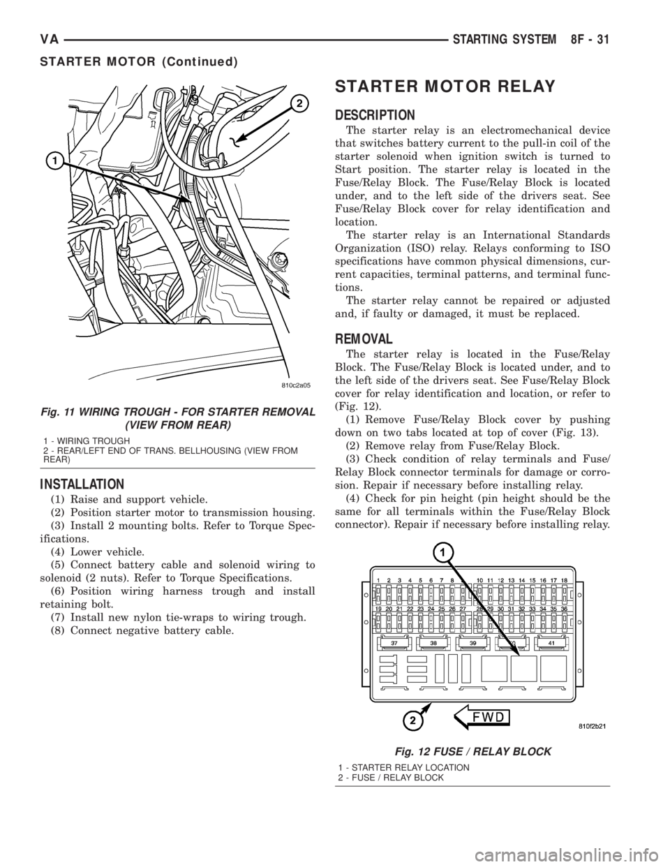
(Fig. 12).
(1) Remove Fuse/Relay Block cover by pushing
down on two tabs located at top of cover (Fig. 13).
(2) Remove relay from Fuse/Relay Block.
(3) Check condition of relay terminals and Fuse/
Relay Block connector terminals for damage or corro-
sion. Repair if necessary before installing relay.
(4) Check for pin height (pin height should be the
same for all terminals within the Fuse/Relay Block
connector). Repair if necessary before installing relay.
Fig. 11 WIRING TROUGH - FOR STARTER REMOVAL
(VIEW FROM REAR)
1 - WIRING TROUGH
2 - REAR/LEFT END OF TRANS. BELLHOUSING (VIEW FROM
REAR)
Fig. 12 FUSE / RELAY BLOCK
1 - STARTER RELAY LOCATION
2 - FUSE / RELAY BLOCK
VASTARTING SYSTEM 8F - 31
STARTER MOTOR (Continued)
Page 164 of 1232
HEATED SEAT RELAY
DESCRIPTION
The heated seat relay is an electromechanical
device that switches 12v battery current to the
heated seat elements when the relay control coil is
energized. The heated seat relay is located in the
Fuse Block, under the drivers seat. The heated seat
relay is a International Standards Organization
(ISO) relay. Relays conforming to the ISO specifica-
tions have common physical dimensions, current
capacities, terminal patterns, and terminal functions.
The heated seat relay cannot be repaired or
adjusted and, if faulty or damaged, it must be
replaced.
OPERATION
The ISO relay consists of an electromagnetic coil, a
resistor or diode, and three (two fixed and one mov-
able) electrical contacts. The movable (common feed)
relay contact is held against one of the fixed contacts
(normally closed) by spring pressure. When the elec-
tromagnetic coil is energized, it draws the movable
contact away from the normally closed fixed contact,
and holds it against the other (normally open) fixed
contact. When the electromagnetic coil is de-ener-
gized, spring pressure returns the movable contact to
the normally closed position. The resistor or diode is
connected in parallel with the electromagnetic coil in
the relay, and helps to dissipate voltage spikes that
are produced when the coil is de-energized.
DIAGNOSIS AND TESTING - HEATED SEAT
RELAY
The heated seat relay is located in the Fuse Block,
under the drivers seat. Refer toWiringfor the loca-
tion of complete heated seat system wiring diagrams.
(1) Remove the heated seat relay from the fuse
block.
(2) A relay in the de-energized position should
have continuity between terminals 87A and 30, and
no continuity between terminals 87 and 30. If OK, go
to Step 3. If not OK, replace the faulty relay.
(3) Resistance between terminals 85 and 86 (elec-
tromagnet) should be 75 5 ohms. If OK, go to Step
4. If not OK, replace the faulty relay.
(4) Connect a battery to terminals 85 and 86.
There should now be continuity between terminals
30 and 87, and no continuity between terminals 87A
and 30. If OK, check the relay supply circuits. If not
OK, replace the faulty relay.
REMOVAL
(1) Disconnect and isolate the battery negative
cable.
(2) The heated seat relay is located in the fuse
block, under the drivers seat. Refer to wiring for
detailed location.
(3) Grasp the heated seat relay firmly and pull it
straight out from the fuse block. A slight rocking
motion will aid in removal.
INSTALLATION
(1) Grasp the heated seat relay firmly and push it
straight in the fuse block.
(2) Reconnect the battery negative cable.
HEATED SEAT SENSOR
DESCRIPTION
The heated seat temperature sensor is a Negative
Temperature Coefficient (NTC) thermistor. One tem-
perature sensor is used for each seat. The sensor is
located in the seat cushion heating element for all
models.
The heated seat sensor cannot be adjusted or
repaired and if it is found to be faulty, the complete
heated seat element must be replaced.
DIAGNOSIS AND TESTING - HEATED SEAT
SENSOR
For complete circuit diagrams, refer toWiring.
NOTE: Any resistance values (ohmsV) given in the
following text are supplied using the automatic
range generated by a FLUKETautomotive meter. If
another type of measuring device is used the val-
ues generated may not be the same as the results
shown here, or may have to be converted to the
range used here.
(1) Backprobe the heated seat relay wire harness
connector, do not disconnect. Using an voltmeter,
check the voltage of the seat temperature sensor
input cavity of the heated seat relay wire harness
connector. The seat sensor input voltage should be
between 1.7 volts and 3.0 volts with the system ON.
If OK, sensor is OK at this time. If not OK, replace
the faulty seat cushion heating element and sensor
assembly.
8G - 4 HEATED SYSTEMSVA
Page 302 of 1232
(2) Install and tighten the three screws that secure
the wiper motor to the wiper linkage module motor
bracket. Tighten the screws to 12 N´m (105 in. lbs.).
(3) If this wiper motor is being reinstalled, position
the motor crank arm on the wiper motor output shaft
so that the index marks made during the removal
procedure are aligned. If this is a new wiper motor
installation, the motor crank arm should be installed
so that it is pointed toward the left (driver) side of
the vehicle and parallel with the two wiper drive
links while both wiper blades are positioned on their
alignment marks near the lower edge of the wind-
shield glass.
(4) Install and tighten the nut that secures the
motor crank arm to the wiper motor output shaft.
Tighten the nut to 12 N´m (105 in. lbs.).
(5) Reconnect the vehicle wire harness connector
for the wiper motor to the motor pigtail wire connec-
tor.
(6) Reconnect the battery negative cable.WIPER RELAY
DESCRIPTION
A wiper relay is standard equipment on all models.
The wiper relay (or intermittent wipe relay) is
located in a dedicated receptacle on the bottom left of
the fuse block on the underside of the steering col-
umn (Fig. 25). The wiper relay is a conventional
International Standards Organization (ISO) micro
relay. Relays conforming to the ISO specifications
have common physical dimensions, current capaci-
ties, terminal patterns, and terminal functions. The
relay is contained within a small, rectangular,
molded plastic housing. The relay is connected to all
of the required inputs and outputs through the
instrument panel wire harness connector by five
male spade-type terminals that extend from the bot-
tom of the relay base. The ISO designation for each
terminal is molded into the base adjacent to the ter-
minal. The ISO terminal designations are as follows:
²30 (Common Feed)- This terminal is con-
nected to the movable contact point of the relay.
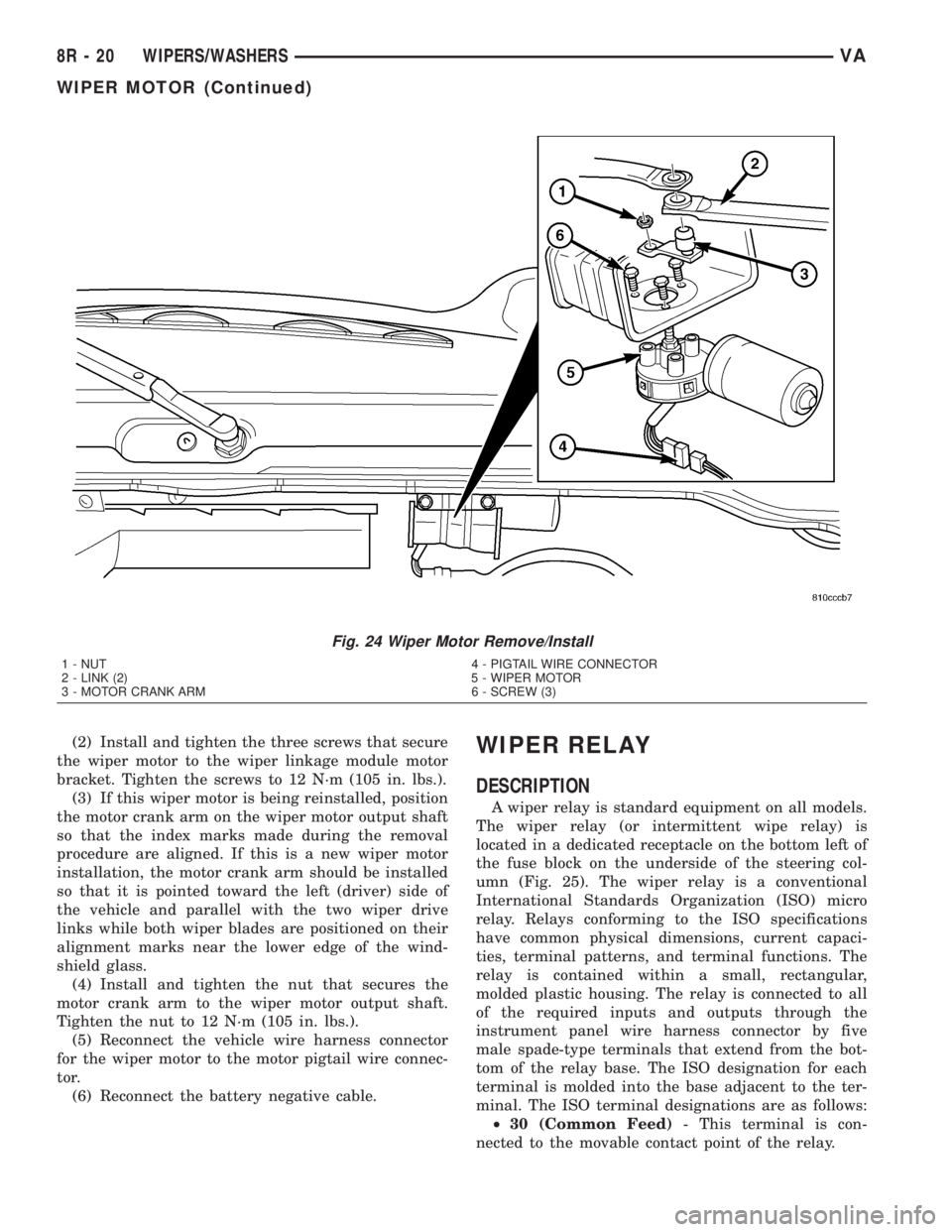
Fig. 24 Wiper Motor Remove/Install
1 - NUT 4 - PIGTAIL WIRE CONNECTOR
2 - LINK (2) 5 - WIPER MOTOR
3 - MOTOR CRANK ARM 6 - SCREW (3)
8R - 20 WIPERS/WASHERSVA
WIPER MOTOR (Continued)
Page 736 of 1232
OPERATION
The power outlet base or receptacle shell is con-
nected to ground, and an insulated contact in the
bottom of the shell is connected to battery current.
The power outlet receives battery voltage from a fuse
in the fuse block at all times.
DIAGNOSIS AND TESTING - POWER OUTLET
(1) Check for battery voltage at the fused B(+) fuse
in the fuse block. If OK, go to Step 2. If not OK,
repair the open fused B(+) circuit to the battery as
required.
(2) Check for continuity between the inside cir-
cumference of the power outlet receptacle and a good
ground. There should be continuity. If OK, go to Step
3. If not OK, go to Step 4.
(3) Check for battery voltage at the insulated con-
tact located at the back of the power outlet recepta-
cle. If not OK, go to Step 4.
(4) Disconnect and isolate the battery negative
cable. Check for continuity between the ground cir-
cuit cavity of the power outlet wire harness connector
and a good ground. There should be continuity. If
OK, go to Step 5. If not OK, repair the open ground
circuit to ground as required.
(5) Connect the battery negative cable. Check for
battery voltage at the fused B(+) circuit cavity of the
power outlet wire harness connector. If OK, replace
the faulty power outlet receptacle. If not OK, repair
the open fused B(+) circuit to the fuse in the fuse
block as required.
REMOVAL
(1) Disconnect and isolate the battery negative
cable.
(2) Pull the cigar lighter knob and element out of
the cigar lighter receptacle base, or unsnap the pro-
tective cap from the power outlet receptacle base.
(3) Look inside the cigar lighter or power outlet
receptacle base and note the position of the rectangu-
lar retaining bosses of the mount that secures the
receptacle base to the instrument panel.
(4) Insert a pair of external snap ring pliers into
the cigar lighter or power outlet receptacle base and
engage the tips of the pliers with the retaining
bosses of the mount.
(5) Squeeze the pliers to disengage the mount
retaining bosses from the receptacle base and, using
a gentle rocking motion, pull the pliers and the
receptacle base out of the mount.
(6) Disconnect the instrument panel wire harness
connector from the connector receptacle of the cigar
lighter or the power outlet receptacle base.
(7) Remove the cigar lighter or power outlet mount
from the instrument panel.
INSTALLATION
(1) Install the cigar lighter or power outlet mount
into the instrument panel.
(2) Reconnect the instrument panel wire harness
connector to the connector receptacle of the cigar
lighter or the power outlet receptacle base.
(3) Align the splines on the outside of the cigar
lighter or power outlet receptacle base connector
receptacle with the grooves on the inside of the
mount.
(4) Press firmly on the cigar lighter or power out-
let receptacle base until the retaining bosses of the
mount are fully engaged in their receptacles.
(5) Install the cigar lighter knob and element into
the cigar lighter receptacle base.
(6) Reconnect the battery negative cable.
RELAY
DESCRIPTION
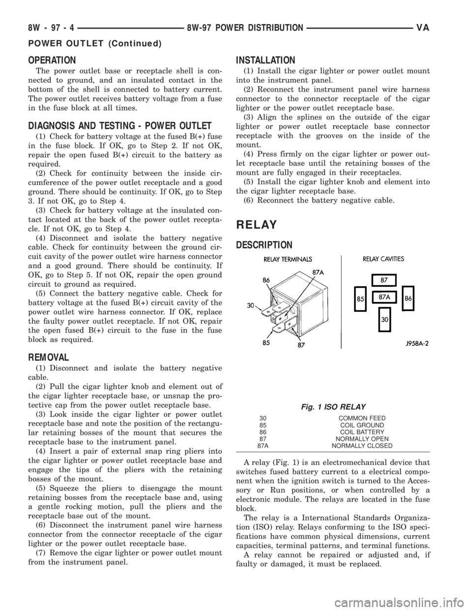
A relay (Fig. 1) is an electromechanical device that
switches fused battery current to a electrical compo-
nent when the ignition switch is turned to the Acces-
sory or Run positions, or when controlled by a
electronic module. The relays are located in the fuse
block.
The relay is a International Standards Organiza-
tion (ISO) relay. Relays conforming to the ISO speci-
fications have common physical dimensions, current
capacities, terminal patterns, and terminal functions.
A relay cannot be repaired or adjusted and, if
faulty or damaged, it must be replaced.
Fig. 1 ISO RELAY
30 COMMON FEED
85 COIL GROUND
86 COIL BATTERY
87 NORMALLY OPEN
87A NORMALLY CLOSED
8W - 97 - 4 8W-97 POWER DISTRIBUTIONVA
POWER OUTLET (Continued)
Page 819 of 1232
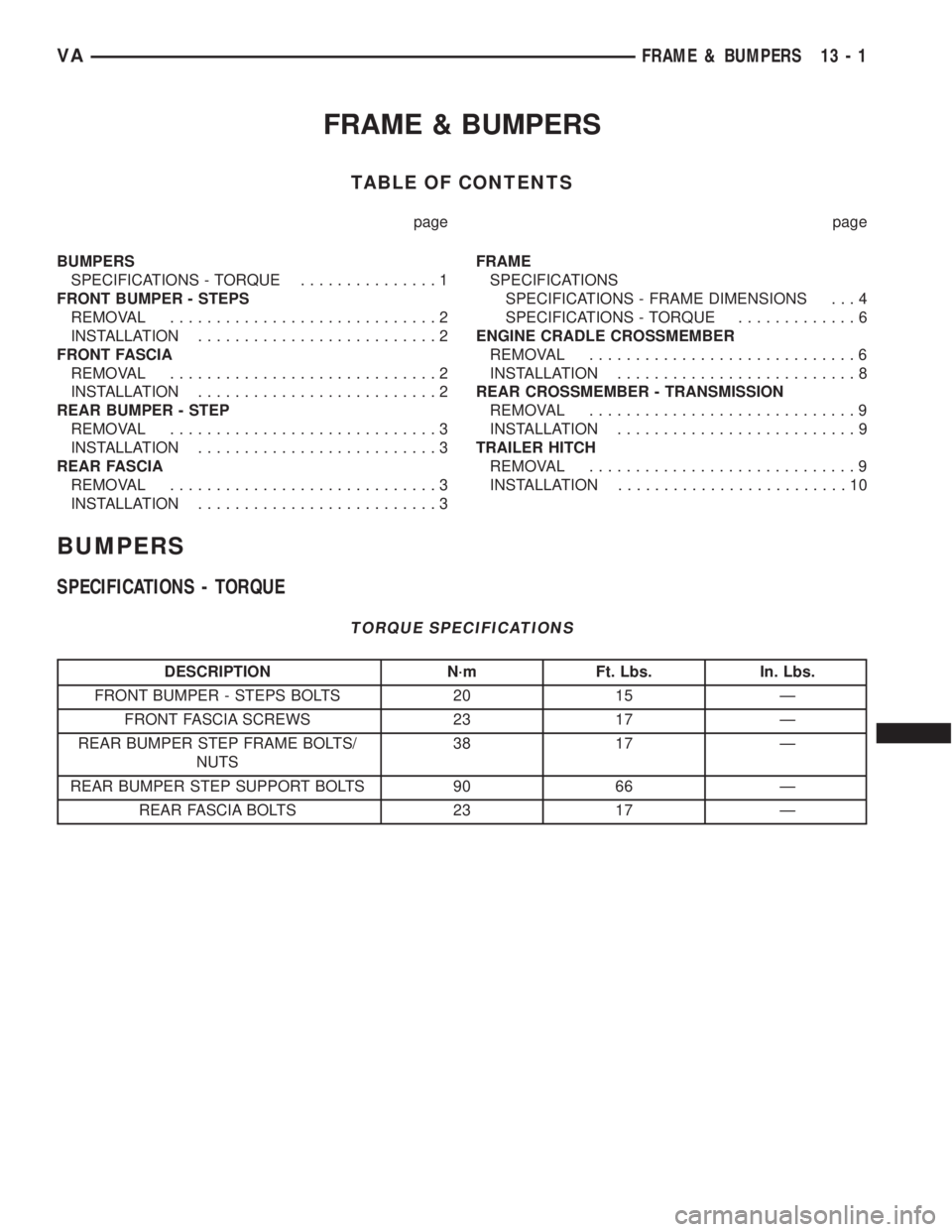
FRAME & BUMPERS
TABLE OF CONTENTS
page page
BUMPERS
SPECIFICATIONS - TORQUE...............1
FRONT BUMPER - STEPS
REMOVAL.............................2
INSTALLATION..........................2
FRONT FASCIA
REMOVAL.............................2
INSTALLATION..........................2
REAR BUMPER - STEP
REMOVAL.............................3
INSTALLATION..........................3
REAR FASCIA
REMOVAL.............................3
INSTALLATION..........................3FRAME
SPECIFICATIONS
SPECIFICATIONS - FRAME DIMENSIONS . . . 4
SPECIFICATIONS - TORQUE.............6
ENGINE CRADLE CROSSMEMBER
REMOVAL.............................6
INSTALLATION..........................8
REAR CROSSMEMBER - TRANSMISSION
REMOVAL.............................9
INSTALLATION..........................9
TRAILER HITCH
REMOVAL.............................9
INSTALLATION.........................10
BUMPERS
SPECIFICATIONS - TORQUE
TORQUE SPECIFICATIONS
DESCRIPTION N´m Ft. Lbs. In. Lbs.
FRONT BUMPER - STEPS BOLTS 20 15 Ð
FRONT FASCIA SCREWS 23 17 Ð
REAR BUMPER STEP FRAME BOLTS/
NUTS38 17 Ð
REAR BUMPER STEP SUPPORT BOLTS 90 66 Ð
REAR FASCIA BOLTS 23 17 Ð
VAFRAME & BUMPERS 13 - 1
Page 822 of 1232
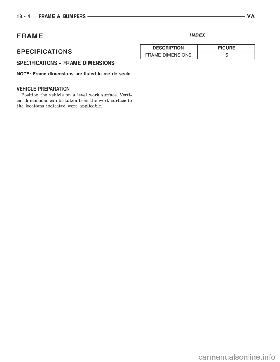
FRAME
SPECIFICATIONS
SPECIFICATIONS - FRAME DIMENSIONS
NOTE: Frame dimensions are listed in metric scale.
VEHICLE PREPARATION
Position the vehicle on a level work surface. Verti-
cal dimensions can be taken from the work surface to
the locations indicated were applicable.
INDEX
DESCRIPTION FIGURE
FRAME DIMENSIONS 5
13 - 4 FRAME & BUMPERSVA
Page 823 of 1232

Fig. 5 FRAME DIMENSIONS
VAFRAME & BUMPERS 13 - 5
FRAME (Continued)
Page 1126 of 1232
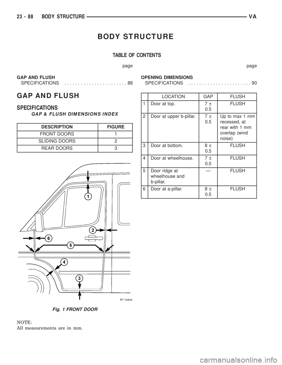
BODY STRUCTURE
TABLE OF CONTENTS
page page
GAP AND FLUSH
SPECIFICATIONS.......................88OPENING DIMENSIONS
SPECIFICATIONS.......................90
GAP AND FLUSH
SPECIFICATIONS
GAP & FLUSH DIMENSIONS INDEX
DESCRIPTION FIGURE
FRONT DOORS 1
SLIDING DOORS 2
REAR DOORS 3
NOTE:
All measurements are in mm.
LOCATION GAP FLUSH
1 Door at top. 7
0.5FLUSH
2 Door at upper b-pillar. 7
0.5Up to max 1 mm
recessed, at
rear with 1 mm
overlap (wind
noise)
3 Door at bottom. 8
0.5FLUSH
4 Door at wheelhouse. 7
0.5FLUSH
5 Door ridge at
wheelhouse and
b-pillar.Ð FLUSH
6 Door at a-pillar. 8
0.5FLUSH
Fig. 1 FRONT DOOR
23 - 88 BODY STRUCTUREVA