2005 MERCEDES-BENZ SPRINTER pinion
[x] Cancel search: pinionPage 42 of 1232
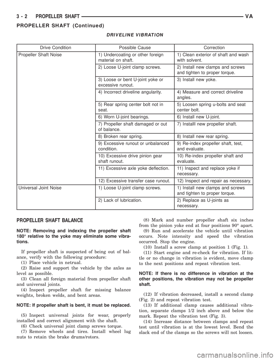
DRIVELINE VIBRATION
Drive Condition Possible Cause Correction
Propeller Shaft Noise 1) Undercoating or other foreign
material on shaft.1) Clean exterior of shaft and wash
with solvent.
2) Loose U-joint clamp screws. 2) Install new clamps and screws
and tighten to proper torque.
3) Loose or bent U-joint yoke or
excessive runout.3) Install new yoke.
4) Incorrect driveline angularity. 4) Measure and correct driveline
angles.
5) Rear spring center bolt not in
seat.5) Loosen spring u-bolts and seat
center bolt.
6) Worn U-joint bearings. 6) Install new U-joint.
7) Propeller shaft damaged or out
of balance.7) Installl new propeller shaft.
8) Broken rear spring. 8) Install new rear spring.
9) Excessive runout or unbalanced
condition.9) Re-index propeller shaft, test,
and evaluate.
10) Excessive drive pinion gear
shaft runout.10) Re-index propeller shaft and
evaluate.
11) Excessive axle yoke deflection. 11) Inspect and replace yoke if
necessary.
12) Excessive transfer case runout. 12) Inspect and repair as necessary.
Universal Joint Noise 1) Loose U-joint clamp screws. 1) Install new clamps and screws
and tighten to proper torque.
2) Lack of lubrication. 2) Replace as U-joints as
necessary.
PROPELLER SHAFT BALANCE
NOTE: Removing and indexing the propeller shaft
180É relative to the yoke may eliminate some vibra-
tions.
If propeller shaft is suspected of being out of bal-
ance, verify with the following procedure:
(1) Place vehicle in netrual.
(2) Raise and support the vehicle by the axles as
level as possible.
(3) Clean all foreign material from propeller shaft
and universal joints.
(4) Inspect propeller shaft for missing balance
weights, broken welds, and bent areas.
NOTE: If propeller shaft is bent, it must be replaced.
(5) Inspect universal joints for wear, properly
installed and correct alignment with the shaft.
(6) Check universal joint clamp screws torque.
(7) Remove wheels and tires. Install wheel lug
nuts to retain the brake drums/rotors.(8) Mark and number propeller shaft six inches
from the pinion yoke end at four positions 90É apart.
(9) Run and accelerate the vehicle until vibration
occurs. Note intensity and speed the vibration
occurred. Stop the engine.
(10) Install a screw clamp at position 1 (Fig. 1).
(11) Start engine and re-check for vibration. If lit-
tle or no change in vibration is evident, move clamp
to the next positions and repeat vibration test.
NOTE: If there is no difference in vibration at the
other positions, the vibration may not be propeller
shaft.
(12) If vibration decreased, install a second clamp
(Fig. 2) and repeat vibration test.
(13) If additional clamp causes additional vibra-
tion, separate clamps 1/2 inch above and below the
mark. Repeat the vibration test (Fig. 3).
(14) Increase distance between clamps and repeat
test until vibration is at the lowest level. Bend the
slack end of the clamps so the screws will not loosen.
3 - 2 PROPELLER SHAFTVA
PROPELLER SHAFT (Continued)
Page 44 of 1232
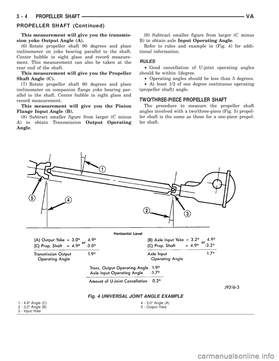
This measurement will give you the transmis-
sion yoke Output Angle (A).
(6) Rotate propeller shaft 90 degrees and place
inclinometer on yoke bearing parallel to the shaft.
Center bubble in sight glass and record measure-
ment. This measurement can also be taken at the
rear end of the shaft.
This measurement will give you the Propeller
Shaft Angle (C).
(7) Rotate propeller shaft 90 degrees and place
inclinometer on companion flange yoke bearing par-
allel to the shaft. Center bubble in sight glass and
record measurement.
This measurement will give you the Pinion
Flange Input Angle (B).
(8) Subtract smaller figure from larger (C minus
A) to obtain TransmissionOutput Operating
Angle.(9) Subtract smaller figure from larger (C minus
B) to obtain axleInput Operating Angle.
Refer to rules and example in (Fig. 4) for addi-
tional information.
RULES
²Good cancellation of U-joint operating angles
should be within 1degree.
²Operating angles should be less than 3 degrees.
²At least 1/2 of one degree continuous operating
(propeller shaft) angle.
TWO/THREE-PIECE PROPELLER SHAFT
The procedure to measure the propeller shaft
angles involved with a two/three-piece (Fig. 5) propel-
ler shaft is the same as those for a one-piece propel-
ler shaft.
Fig. 4 UNIVERSAL JOINT ANGLE EXAMPLE
1 - 4.9É Angle (C)
2 - 3.2É Angle (B)
3 - Input Yoke4 - 3.0É Angle (A)
5 - Output Yoke
3 - 4 PROPELLER SHAFTVA
PROPELLER SHAFT (Continued)
Page 50 of 1232
REAR AXLE
TABLE OF CONTENTS
page page
REAR AXLE
DESCRIPTION.........................10
OPERATION...........................10
DIAGNOSIS AND TESTING................10
STANDARD PROCEDURE - DRAIN AND FILL . . 11
REMOVAL.............................11
INSTALLATION.........................12
SPECIFICATIONS.......................13
SPECIAL TOOLS.......................14
AXLE SHAFTS
REMOVAL.............................15
INSTALLATION.........................15AXLE BEARINGS/SEALS
REMOVAL.............................17
INSTALLATION.........................17
AXLE SHAFTS - DUAL REAR WHEELS
REMOVAL.............................19
INSTALLATION.........................19
AXLE HUB BEARINGS/SEALS
REMOVAL.............................20
INSTALLATION.........................20
PINION SEAL
REMOVAL.............................22
INSTALLATION.........................22
REAR AXLE
DESCRIPTION
The axle housings consist of a cast iron center sec-
tion with axle tubes extending from either side. The
tubes are pressed into and welded to the differential
housing to form a one-piece axle housing. The SRW
axle has semi-floating axle shafts, DRW has full-
floating axle shafts.
NOTE: Axle seals, axle bearings, pinion seal and
differential cover are the only serviceble compo-
nents. If differential is damaged/noisy the axle must
be replaced.
OPERATION
The axle receives power from the transmission
through the rear propeller shaft. The rear propeller
shaft is connected to the pinion gear which rotates
the differential through the gear mesh with the ring
gear bolted to the differential case. The engine power
is transmitted to the axle shafts through the pinion
mate and side gears. The side gears are splined to
the axle shafts.
DIAGNOSIS AND TESTING
NOTE: Axle seals, axle bearings, pinion seals and
differential cover are the only serviceble compo-
nents. If differential is damaged/noisy the axle must
be replaced.
GEAR NOISE
Axle gear noise can be caused by insufficient lubri-
cant, incorrect backlash, incorrect pinion depth, tooth
contact, worn/damaged gears, or the carrier housing
not having the proper offset and squareness.
Gear noise usually happens at a specific speed
range. The noise can also occur during a specific type
of driving condition. These conditions are accelera-
tion, deceleration, coast, or constant load.
When road testing, first warm-up the axle fluid by
driving the vehicle at least 5 miles and then acceler-
ate the vehicle to the speed range where the noise is
the greatest. Shift out-of-gear and coast through the
peak-noise range. If the noise stops or changes
greatly:
²Check for insufficient lubricant.
²Incorrect ring gear backlash.
²Gear damage.
Differential side gears and pinions can be checked
by turning the vehicle. They usually do not cause
noise during straight-ahead driving when the gears
are unloaded. The side gears are loaded during vehi-
cle turns. A worn pinion shaft can also cause a snap-
ping or a knocking noise.
BEARING NOISE
The axle shaft, differential and pinion bearings can
all produce noise when worn or damaged. Bearing
noise can be either a whining, or a growling sound.
Pinion bearingshave a constant-pitch noise. This
noise changes only with vehicle speed. Pinion bearing
noise will be higher pitched because it rotates at a
faster rate. Drive the vehicle and load the differen-
tial. If bearing noise occurs, the rear pinion bearing
is the source of the noise. If the bearing noise is
3 - 10 REAR AXLEVA
Page 51 of 1232
heard during a coast, the front pinion bearing is the
source.
Differential bearings usually produce a low pitch
noise. Differential bearing noise is similar to pinion
bearing noise. The pitch of differential bearing noise
is also constant and varies only with vehicle speed.
Axle shaft bearingsproduce noise and vibration
when worn or damaged. The noise generally changes
when the bearings are loaded. Road test the vehicle.
Turn the vehicle sharply to the left and to the right.
This will load the bearings and change the noise
level. Where axle bearing damage is slight, the noise
is usually not noticeable at speeds above 30 mph.
LOW SPEED KNOCK
Low speed knock is generally caused by a worn
U-joint or by worn side-gear thrust washers. A worn
pinion shaft bore will also cause low speed knock.
VIBRATION
Vibration at the rear of the vehicle is usually
caused by a:
²Damaged drive shaft.
²Missing drive shaft balance weight(s).
²Worn or out-of-balance wheels.
²Loose wheel lug nuts.
²Worn U-joint(s).
²Loose/broken springs.
²Damaged axle shaft bearing(s).
²Loose pinion gear nut.
²Excessive pinion yoke run out.
²Bent axle shaft(s).
Check for loose or damaged front-end components
or engine/transmission mounts. These components
can contribute to what appears to be a rearend vibra-
tion. Do not overlook engine accessories, brackets
and drive belts.
NOTE: All driveline components should be exam-
ined before starting any repair.
DRIVELINE SNAP
A snap or clunk noise when the vehicle is shifted
into gear (or the clutch engaged), can be caused by:
²High engine idle speed.
²Transmission shift operation.
²Loose engine/transmission/transfer case mounts.
²Worn U-joints.
²Loose spring mounts.
²Loose pinion gear nut and yoke.
²Excessive ring gear backlash.
²Excessive side gear to case clearance.
The source of a snap or a clunk noise can be deter-
mined with the assistance of a helper. Raise the vehi-
cle on a hoist with the wheels free to rotate. Instruct
the helper to shift the transmission into gear. Listenfor the noise, a mechanics stethoscope is helpful in
isolating the source of a noise.
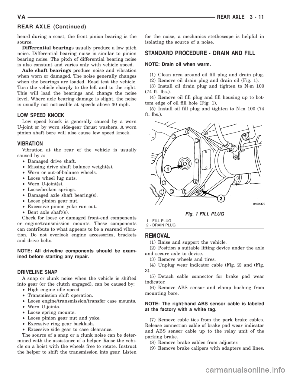
STANDARD PROCEDURE - DRAIN AND FILL
NOTE: Drain oil when warm.
(1) Clean area around oil fill plug and drain plug.
(2) Remove oil drain plug and drain oil (Fig. 1).
(3) Install oil drain plug and tighten to N´m 100
(74 ft. lbs.).
(4) Remove oil fill plug and fill housing up to bot-
tom edge of oil fill hole (Fig. 1).
(5) Install oil fill plug and tighten to N´m 100 (74
ft. lbs.).
REMOVAL
(1) Raise and support the vehicle.
(2) Position a suitable lifting device under the axle
and secure axle to device.
(3) Remove wheels and tires.
(4) Unplug wear indicator cable (Fig. 2) and (Fig.
3).
(5) Detach cable connector for brake pad wear
indicator.
(6) Remove ABS sensor and clamp bushing from
mounting bore.
NOTE: The right-hand ABS sensor cable is labeled
at the factory with a white tag.
(7) Remove cable ties from the park brake cables.
Release connection cable of brake pad wear indicator
and ABS sensor cable up to the relay unit of the
parking brake.
(8) Remove brake cables from adjuster.
(9) Remove brake calipers with adapters and lines.
Fig. 1 FILL PLUG
1 - FILL PLUG
2 - DRAIN PLUG
VAREAR AXLE 3 - 11
REAR AXLE (Continued)
Page 62 of 1232
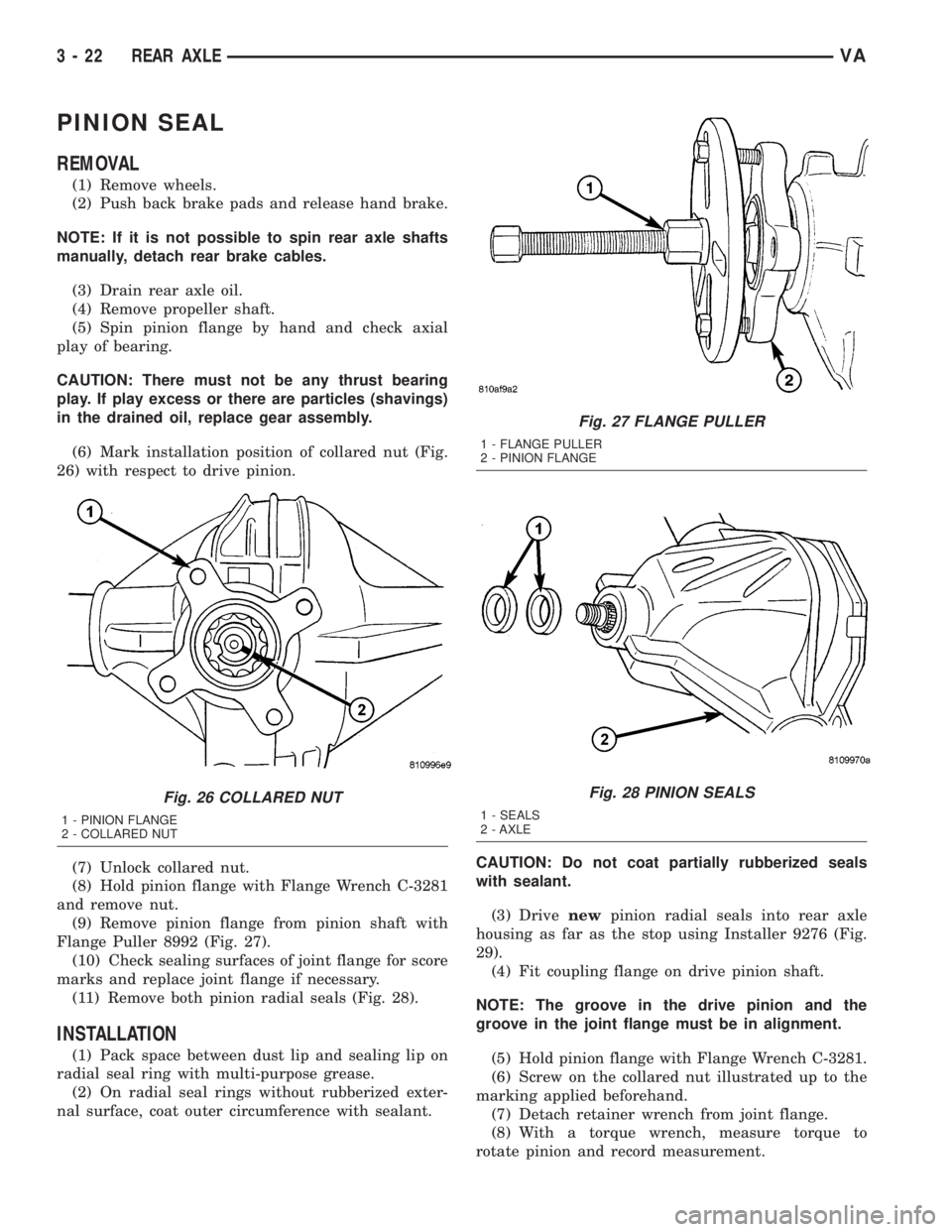
PINION SEAL
REMOVAL
(1) Remove wheels.
(2) Push back brake pads and release hand brake.
NOTE: If it is not possible to spin rear axle shafts
manually, detach rear brake cables.
(3) Drain rear axle oil.
(4) Remove propeller shaft.
(5) Spin pinion flange by hand and check axial
play of bearing.
CAUTION: There must not be any thrust bearing
play. If play excess or there are particles (shavings)
in the drained oil, replace gear assembly.
(6) Mark installation position of collared nut (Fig.
26) with respect to drive pinion.
(7) Unlock collared nut.
(8) Hold pinion flange with Flange Wrench C-3281
and remove nut.
(9) Remove pinion flange from pinion shaft with
Flange Puller 8992 (Fig. 27).
(10) Check sealing surfaces of joint flange for score
marks and replace joint flange if necessary.
(11) Remove both pinion radial seals (Fig. 28).
INSTALLATION
(1) Pack space between dust lip and sealing lip on
radial seal ring with multi-purpose grease.
(2) On radial seal rings without rubberized exter-
nal surface, coat outer circumference with sealant.CAUTION: Do not coat partially rubberized seals
with sealant.
(3) Drivenewpinion radial seals into rear axle
housing as far as the stop using Installer 9276 (Fig.
29).
(4) Fit coupling flange on drive pinion shaft.
NOTE: The groove in the drive pinion and the
groove in the joint flange must be in alignment.
(5) Hold pinion flange with Flange Wrench C-3281.
(6) Screw on the collared nut illustrated up to the
marking applied beforehand.
(7) Detach retainer wrench from joint flange.
(8) With a torque wrench, measure torque to
rotate pinion and record measurement.
Fig. 26 COLLARED NUT
1 - PINION FLANGE
2 - COLLARED NUT
Fig. 27 FLANGE PULLER
1 - FLANGE PULLER
2 - PINION FLANGE
Fig. 28 PINION SEALS
1 - SEALS
2 - AXLE
3 - 22 REAR AXLEVA
Page 63 of 1232
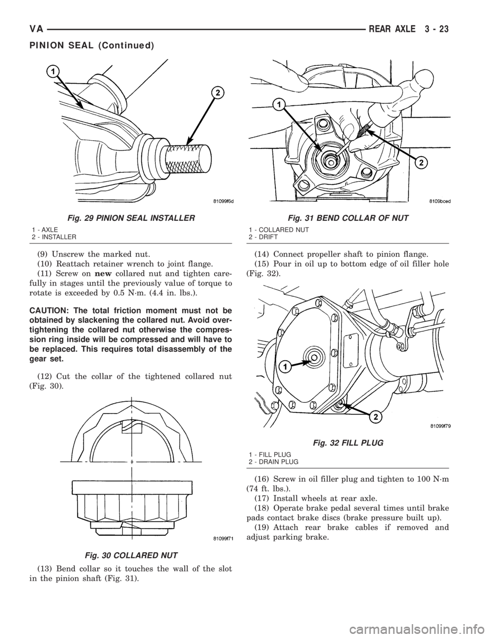
(9) Unscrew the marked nut.
(10) Reattach retainer wrench to joint flange.
(11) Screw onnewcollared nut and tighten care-
fully in stages until the previously value of torque to
rotate is exceeded by 0.5 N´m. (4.4 in. lbs.).
CAUTION: The total friction moment must not be
obtained by slackening the collared nut. Avoid over-
tightening the collared nut otherwise the compres-
sion ring inside will be compressed and will have to
be replaced. This requires total disassembly of the
gear set.
(12) Cut the collar of the tightened collared nut
(Fig. 30).
(13) Bend collar so it touches the wall of the slot
in the pinion shaft (Fig. 31).(14) Connect propeller shaft to pinion flange.
(15) Pour in oil up to bottom edge of oil filler hole
(Fig. 32).
(16) Screw in oil filler plug and tighten to 100 N´m
(74 ft. lbs.).
(17) Install wheels at rear axle.
(18) Operate brake pedal several times until brake
pads contact brake discs (brake pressure built up).
(19) Attach rear brake cables if removed and
adjust parking brake.
Fig. 29 PINION SEAL INSTALLER
1 - AXLE
2 - INSTALLER
Fig. 30 COLLARED NUT
Fig. 31 BEND COLLAR OF NUT
1 - COLLARED NUT
2 - DRIFT
Fig. 32 FILL PLUG
1 - FILL PLUG
2 - DRAIN PLUG
VAREAR AXLE 3 - 23
PINION SEAL (Continued)
Page 152 of 1232
STARTING SYSTEM
TABLE OF CONTENTS
page page
STARTING SYSTEM
DESCRIPTION.........................24
OPERATION...........................24
DIAGNOSIS AND TESTING - STARTING
SYSTEM............................25
SPECIFICATIONS
TORQUE - STARTER - DIESEL...........29
SPECIFICATIONS - STARTER MOTOR -
DIESEL.............................29STARTER MOTOR
DIAGNOSIS AND TESTING - STARTER
MOTOR .............................29
REMOVAL.............................30
INSTALLATION.........................31
STARTER MOTOR RELAY
DESCRIPTION.........................31
REMOVAL.............................31
INSTALLATION.........................32
STARTING SYSTEM
DESCRIPTION
The starting system consists of:
²Starter relay
²Starter motor (including an integral starter sole-
noid)
Other components to be considered as part of start-
ing system are:
²Battery
²Battery cables
²Ignition switch and key lock cylinder
²Park/neutral position switch (automatic trans-
mission)
²Wire harnesses and connections.
The Battery, Starting, and Charging systems oper-
ate in conjunction with one another, and must be
tested as a complete system. For correct operation of
starting/charging systems, all components used in
these 3 systems must perform within specifications.
When attempting to diagnose any of these systems, it
is important that you keep their interdependency in
mind.
The diagnostic procedures used in each of these
groups include the most basic conventional diagnostic
methods, to the more sophisticated On-Board Diag-
nostics (OBD) built into the Engine Control Module
(ECM). Use of an induction-type milliampere amme-
ter, volt/ohmmeter, battery charger, carbon pile rheo-
stat (load tester), and 12-volt test lamp may be
required.
Certain starting system components are monitored
by the ECM and may produce a Diagnostic Trouble
Code (DTC).
OPERATION
The starting system components form two separate
circuits. A high-amperage feed circuit that feeds thestarter motor high-amperage, and a low-amperage
control circuit that operates on less than 20 amperes.
The high-amperage feed circuit components include
the battery, the battery cables, the contact disc por-
tion of the starter solenoid, and the starter motor
itself. The low-amperage control circuit components
include the ignition switch, the park/neutral position
switch (automatic transmission), the starter relay,
the electromagnetic windings of the starter solenoid,
and the connecting wire harness components.
If the vehicle is equipped with an automatic trans-
mission, battery voltage is supplied through the low-
amperage control circuit to the coil battery terminal
of the starter relay when the ignition switch is
turned to the momentary Start position. The park/
neutral position switch is installed in series between
the starter relay coil ground terminal and ground.
This normally open switch prevents the starter relay
from being energized and the starter motor from
operating unless the automatic transmission gear
selector is in the Neutral or Park positions.
When the starter relay coil is energized, the nor-
mally open relay contacts close. The relay contacts
connect the relay common feed terminal to the relay
normally open terminal. The closed relay contacts
energize the starter solenoid coil windings.
The energized solenoid pull-in coil pulls in the sole-
noid plunger. The solenoid plunger pulls the shift
lever in the starter motor. This engages the starter
overrunning clutch and pinion gear with the starter
ring gear on the manual transmission flywheel or on
the automatic transmission torque converter or
torque converter drive plate.
As the solenoid plunger reaches the end of its
travel, the solenoid contact disc completes the high-
amperage starter feed circuit and energizes the sole-
noid plunger hold-in coil. Current now flows between
the solenoid battery terminal and the starter motor,
energizing the starter.
8F - 24 STARTING SYSTEMVA
Page 153 of 1232
Once the engine starts, the overrunning clutch pro-
tects the starter motor from damage by allowing the
starter pinion gear to spin faster than the pinion
shaft. When the driver releases the ignition switch to
the On position, the starter relay coil is de-energized.
This causes the relay contacts to open. When the
relay contacts open, the starter solenoid plunger
hold-in coil is de-energized.
When the solenoid plunger hold-in coil is de-ener-
gized, the solenoid plunger return spring returns the
plunger to its relaxed position. This causes the con-
tact disc to open the starter feed circuit, and the shiftlever to disengage the overrunning clutch and pinion
gear from the starter ring gear.
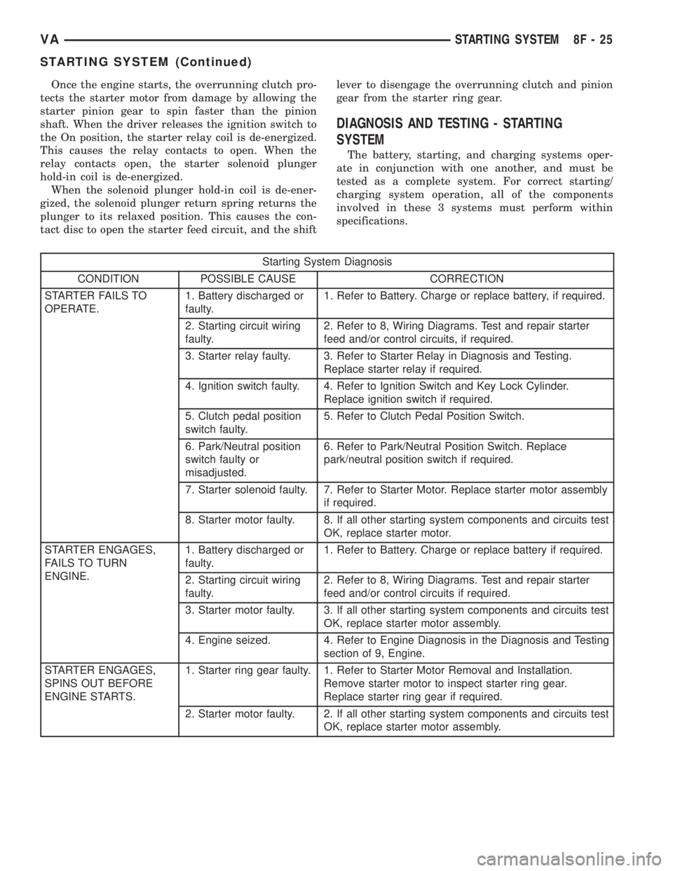
DIAGNOSIS AND TESTING - STARTING
SYSTEM
The battery, starting, and charging systems oper-
ate in conjunction with one another, and must be
tested as a complete system. For correct starting/
charging system operation, all of the components
involved in these 3 systems must perform within
specifications.
Starting System Diagnosis
CONDITION POSSIBLE CAUSE CORRECTION
STARTER FAILS TO
OPERATE.1. Battery discharged or
faulty.1. Refer to Battery. Charge or replace battery, if required.
2. Starting circuit wiring
faulty.2. Refer to 8, Wiring Diagrams. Test and repair starter
feed and/or control circuits, if required.
3. Starter relay faulty. 3. Refer to Starter Relay in Diagnosis and Testing.
Replace starter relay if required.
4. Ignition switch faulty. 4. Refer to Ignition Switch and Key Lock Cylinder.
Replace ignition switch if required.
5. Clutch pedal position
switch faulty.5. Refer to Clutch Pedal Position Switch.
6. Park/Neutral position
switch faulty or
misadjusted.6. Refer to Park/Neutral Position Switch. Replace
park/neutral position switch if required.
7. Starter solenoid faulty. 7. Refer to Starter Motor. Replace starter motor assembly
if required.
8. Starter motor faulty. 8. If all other starting system components and circuits test
OK, replace starter motor.
STARTER ENGAGES,
FAILS TO TURN
ENGINE.1. Battery discharged or
faulty.1. Refer to Battery. Charge or replace battery if required.
2. Starting circuit wiring
faulty.2. Refer to 8, Wiring Diagrams. Test and repair starter
feed and/or control circuits if required.
3. Starter motor faulty. 3. If all other starting system components and circuits test
OK, replace starter motor assembly.
4. Engine seized. 4. Refer to Engine Diagnosis in the Diagnosis and Testing
section of 9, Engine.
STARTER ENGAGES,
SPINS OUT BEFORE
ENGINE STARTS.1. Starter ring gear faulty. 1. Refer to Starter Motor Removal and Installation.
Remove starter motor to inspect starter ring gear.
Replace starter ring gear if required.
2. Starter motor faulty. 2. If all other starting system components and circuits test
OK, replace starter motor assembly.
VASTARTING SYSTEM 8F - 25
STARTING SYSTEM (Continued)