2005 MERCEDES-BENZ SPRINTER parking brake
[x] Cancel search: parking brakePage 4 of 1232
INTERNATIONAL SYMBOLS
DESCRIPTION
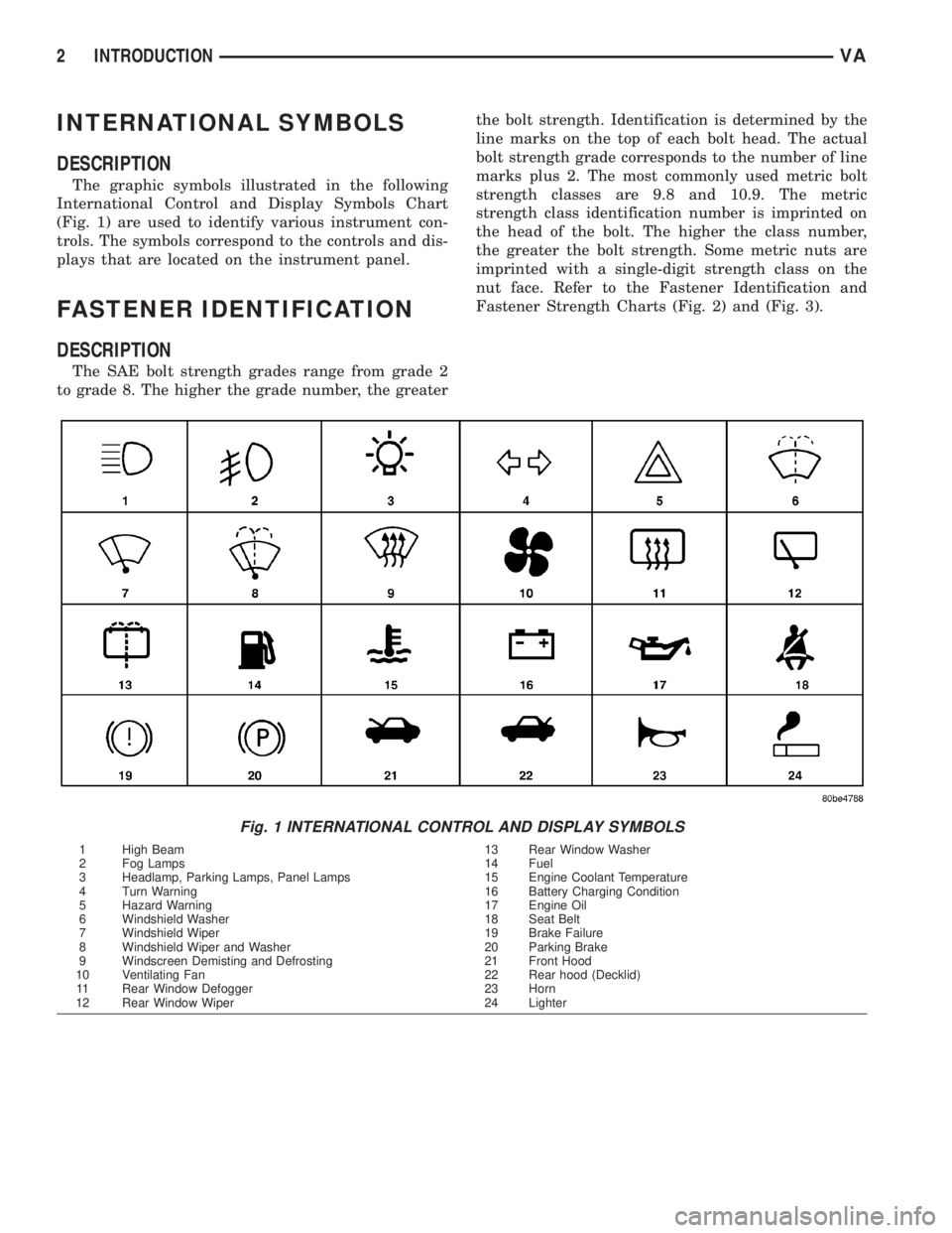
The graphic symbols illustrated in the following
International Control and Display Symbols Chart
(Fig. 1) are used to identify various instrument con-
trols. The symbols correspond to the controls and dis-
plays that are located on the instrument panel.
FASTENER IDENTIFICATION
DESCRIPTION
The SAE bolt strength grades range from grade 2
to grade 8. The higher the grade number, the greaterthe bolt strength. Identification is determined by the
line marks on the top of each bolt head. The actual
bolt strength grade corresponds to the number of line
marks plus 2. The most commonly used metric bolt
strength classes are 9.8 and 10.9. The metric
strength class identification number is imprinted on
the head of the bolt. The higher the class number,
the greater the bolt strength. Some metric nuts are
imprinted with a single-digit strength class on the
nut face. Refer to the Fastener Identification and
Fastener Strength Charts (Fig. 2) and (Fig. 3).
Fig. 1 INTERNATIONAL CONTROL AND DISPLAY SYMBOLS
1 High Beam 13 Rear Window Washer
2 Fog Lamps 14 Fuel
3 Headlamp, Parking Lamps, Panel Lamps 15 Engine Coolant Temperature
4 Turn Warning 16 Battery Charging Condition
5 Hazard Warning 17 Engine Oil
6 Windshield Washer 18 Seat Belt
7 Windshield Wiper 19 Brake Failure
8 Windshield Wiper and Washer 20 Parking Brake
9 Windscreen Demisting and Defrosting 21 Front Hood
10 Ventilating Fan 22 Rear hood (Decklid)
11 Rear Window Defogger 23 Horn
12 Rear Window Wiper 24 Lighter
2 INTRODUCTIONVA
Page 16 of 1232
JUMP STARTING
STANDARD PROCEDURE - JUMP STARTING
WARNING: REVIEW ALL SAFETY PRECAUTIONS
AND WARNINGS IN THE BATTERY SYSTEM SEC-
TION OF THE SERVICE MANUAL. (Refer to 8 -
ELECTRICAL/BATTERY SYSTEM/BATTERY - STAN-
DARD PROCEDURE)
²DO NOT JUMP START A FROZEN BATTERY,
PERSONAL INJURY CAN RESULT.
²IF EQUIPPED, DO NOT JUMP START WHEN
MAINTENANCE FREE BATTERY INDICATOR DOT IS
YELLOW OR BRIGHT COLOR.
²DO NOT JUMP START A VEHICLE WHEN THE
BATTERY FLUID IS BELOW THE TOP OF LEAD
PLATES.
²DO NOT ALLOW JUMPER CABLE CLAMPS TO
TOUCH EACH OTHER WHEN CONNECTED TO A
BOOSTER SOURCE.
²DO NOT USE OPEN FLAME NEAR BATTERY.
²REMOVE METALLIC JEWELRY WORN ON
HANDS OR WRISTS TO AVOID INJURY BY ACCI-
DENTAL ARCING OF BATTERY CURRENT.
²WHEN USING A HIGH OUTPUT BOOSTING
DEVICE, DO NOT ALLOW BATTERY VOLTAGE TO
EXCEED 16 VOLTS. REFER TO INSTRUCTIONS
PROVIDED WITH DEVICE BEING USED.
FAILURE TO FOLLOW THESE INSTRUCTIONS MAY
RESULT IN PERSONAL INJURY.
CAUTION: When using another vehicle as a
booster, do not allow vehicles to touch. Electrical
systems can be damaged on either vehicle.
TO JUMP START A DISABLED VEHICLE:
(1) Raise hood on disabled vehicle and visually
inspect engine compartment for:
²Battery cable clamp condition, clean if necessary.
²Frozen battery.
²Yellow or bright color test indicator, if equipped.
²Low battery fluid level.
²Generator drive belt condition and tension.
²Fuel fumes or leakage, correct if necessary.
CAUTION: If the cause of starting problem on dis-
abled vehicle is severe, damage to booster vehicle
charging system can result.
(2) When using another vehicle as a booster
source, park the booster vehicle within cable reach.
Turn off all accessories, set the parking brake, place
the automatic transmission in PARK or the manual
transmission in NEUTRAL and turn the ignition
OFF.(3) On disabled vehicle, place gear selector in park
or neutral and set park brake. Turn off all accesso-
ries.
(4) Connect jumper cables to booster battery. RED
clamp to positive terminal (+). BLACK clamp to neg-
ative terminal (-). DO NOT allow clamps at opposite
end of cables to touch, electrical arc will result.
Review all warnings in this procedure.
(5) On disabled vehicle, connect RED jumper cable
clamp to positive (+) terminal. Connect BLACK
jumper cable clamp to engine ground as close to the
ground cable attaching point as possible.
(6) Start the engine in the vehicle which has the
booster battery, let the engine idle a few minutes,
then start the engine in the vehicle with the dis-
charged battery.
CAUTION: Do not crank starter motor on disabled
vehicle for more than 15 seconds, starter will over-
heat and could fail.
(7) Allow battery in disabled vehicle to charge to
at least 12.4 volts (75% charge) before attempting to
start engine. If engine does not start within 15 sec-
onds, stop cranking engine and allow starter to cool
(15 min.), before cranking again.
DISCONNECT CABLE CLAMPS AS FOLLOWS:
²Disconnect BLACK cable clamp from engine
ground on disabled vehicle.
²When using a Booster vehicle, disconnect
BLACK cable clamp from battery negative terminal.
Disconnect RED cable clamp from battery positive
terminal.
²Disconnect RED cable clamp from battery posi-
tive terminal on disabled vehicle.
TOWING
STANDARD PROCEDURE - TOWING
WARNING: Do not tow the vehicle if the key cannot
be turned in the ignition lock. If the key cannot be
turned, the ignition lock remains locked and the
vehicle cannot be steered. With the engine not run-
ning there is no power assistance for the braking
and steering systems. In this case, it is important to
keep in mind that a considerably higher degree of
effort is necessary to brake and steer the vehicle.
The vehicle must not be towed with the front axle
raised and the key in position 2 in the ignition lock
as the drive wheels could then lock due to the
acceleration skid control (ASR)
0 - 6 LUBRICATION & MAINTENANCEVA
Page 51 of 1232
heard during a coast, the front pinion bearing is the
source.
Differential bearings usually produce a low pitch
noise. Differential bearing noise is similar to pinion
bearing noise. The pitch of differential bearing noise
is also constant and varies only with vehicle speed.
Axle shaft bearingsproduce noise and vibration
when worn or damaged. The noise generally changes
when the bearings are loaded. Road test the vehicle.
Turn the vehicle sharply to the left and to the right.
This will load the bearings and change the noise
level. Where axle bearing damage is slight, the noise
is usually not noticeable at speeds above 30 mph.
LOW SPEED KNOCK
Low speed knock is generally caused by a worn
U-joint or by worn side-gear thrust washers. A worn
pinion shaft bore will also cause low speed knock.
VIBRATION
Vibration at the rear of the vehicle is usually
caused by a:
²Damaged drive shaft.
²Missing drive shaft balance weight(s).
²Worn or out-of-balance wheels.
²Loose wheel lug nuts.
²Worn U-joint(s).
²Loose/broken springs.
²Damaged axle shaft bearing(s).
²Loose pinion gear nut.
²Excessive pinion yoke run out.
²Bent axle shaft(s).
Check for loose or damaged front-end components
or engine/transmission mounts. These components
can contribute to what appears to be a rearend vibra-
tion. Do not overlook engine accessories, brackets
and drive belts.
NOTE: All driveline components should be exam-
ined before starting any repair.
DRIVELINE SNAP
A snap or clunk noise when the vehicle is shifted
into gear (or the clutch engaged), can be caused by:
²High engine idle speed.
²Transmission shift operation.
²Loose engine/transmission/transfer case mounts.
²Worn U-joints.
²Loose spring mounts.
²Loose pinion gear nut and yoke.
²Excessive ring gear backlash.
²Excessive side gear to case clearance.
The source of a snap or a clunk noise can be deter-
mined with the assistance of a helper. Raise the vehi-
cle on a hoist with the wheels free to rotate. Instruct
the helper to shift the transmission into gear. Listenfor the noise, a mechanics stethoscope is helpful in
isolating the source of a noise.
STANDARD PROCEDURE - DRAIN AND FILL
NOTE: Drain oil when warm.
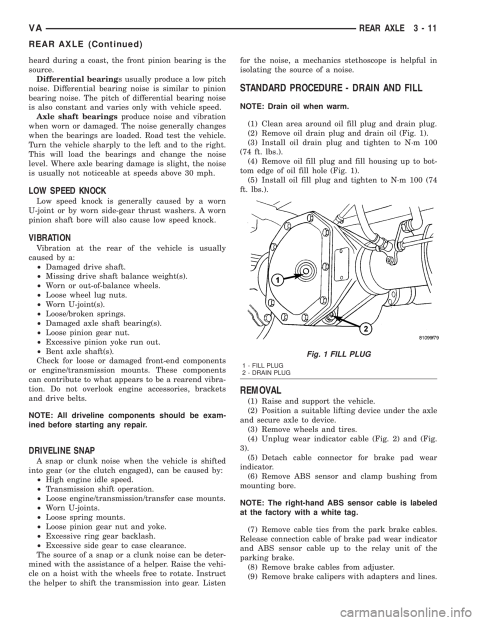
(1) Clean area around oil fill plug and drain plug.
(2) Remove oil drain plug and drain oil (Fig. 1).
(3) Install oil drain plug and tighten to N´m 100
(74 ft. lbs.).
(4) Remove oil fill plug and fill housing up to bot-
tom edge of oil fill hole (Fig. 1).
(5) Install oil fill plug and tighten to N´m 100 (74
ft. lbs.).
REMOVAL
(1) Raise and support the vehicle.
(2) Position a suitable lifting device under the axle
and secure axle to device.
(3) Remove wheels and tires.
(4) Unplug wear indicator cable (Fig. 2) and (Fig.
3).
(5) Detach cable connector for brake pad wear
indicator.
(6) Remove ABS sensor and clamp bushing from
mounting bore.
NOTE: The right-hand ABS sensor cable is labeled
at the factory with a white tag.
(7) Remove cable ties from the park brake cables.
Release connection cable of brake pad wear indicator
and ABS sensor cable up to the relay unit of the
parking brake.
(8) Remove brake cables from adjuster.
(9) Remove brake calipers with adapters and lines.
Fig. 1 FILL PLUG
1 - FILL PLUG
2 - DRAIN PLUG
VAREAR AXLE 3 - 11
REAR AXLE (Continued)
Page 53 of 1232
(10) Install connection cable of brake pad wear
indicator and ABS sensor cable up to the relay unit
of the parking brake.
(11) Install cable ties to the park brake cables.
(12) Install ABS sensor and clamp bushing to
mounting bore.
NOTE: The right-hand ABS sensor cable is labeled
at the factory with a white tag.
(13) Attach connector cable for brake pad wear
indicator.
(14) Plug in cable of brake pad wear indicator.(15) Install the wheels and tires.
(16) Fill axle with appropriate lubricant.
(17) Remove lifting device from under the axle.
(18) Remove support and lower vehicle.
SPECIFICATIONS
AXLE SPECIFICATIONS
DESCRIPTION SPECIFICATION
Axle Ratio 3.73, 4.11
Ring Gear Diameter 216 mm (8.5 in.)
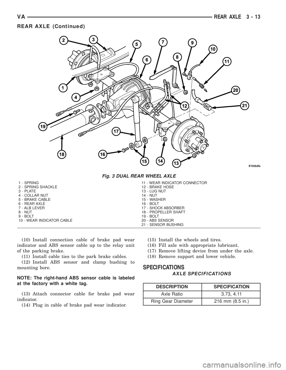
Fig. 3 DUAL REAR WHEEL AXLE
1 - SPRING 11 - WEAR INDICATOR CONNECTOR
2 - SPRING SHACKLE 12 - BRAKE HOSE
3 - PLATE 13 - LUG NUT
4 - COLLAR NUT 14 - NUT
5 - BRAKE CABLE 15 - WASHER
6 - REAR AXLE 16 - BOLT
7 - ALB LEVER 17 - SHOCK ABSORBER
8 - NUT 18 - PROPELLER SHAFT
9 - BOLT 19 - BOLT
10 - WEAR INDICATOR CABLE 20 - ABS SENSOR
21 - SENSOR BUSHING
VAREAR AXLE 3 - 13
REAR AXLE (Continued)
Page 55 of 1232
AXLE SHAFTS
REMOVAL
(1) Remove wheels.
(2) Detach front brake cable.
(3) Pull ABS sensor together with clamp bushing
out of bearing cap (Fig. 4).
(4) Remove brake disk at rear axle. Attach brake
caliper with lines connected in wheel house.
(5) Remove brake shoes of parking brake.
(6) Remove brake control cable lock.
(7) Remove bearing cap bolts and pull axle shaft
out of axle tube (Fig. 4).
(8) Remove seal/gasket.
INSTALLATION
(1) Install sealing ring.
(2) Install rear axle shaft in the axle tube (Fig. 5).
(3) Installnewbearing cap bolts and tighten to 72
N´m (53 ft. lbs.) (Fig. 6).
NOTE: Tighten bolts diagonally across.
(4) Install brake control cable lock.
(5) Install parking brake shoes.
(6) Install brake disk and calipers.
(7) Coat clamping bush with acid-free grease.
Insert ABS sensor with clamping bush fully into the
mounting hole.
(8) Install front brake cable.
(9) Operate brake pedal several times until brake
pads contact brake discs (brake pressure built up).
(10) Install wheels.
WRENCH 9279
FLANGE PULLER 8992
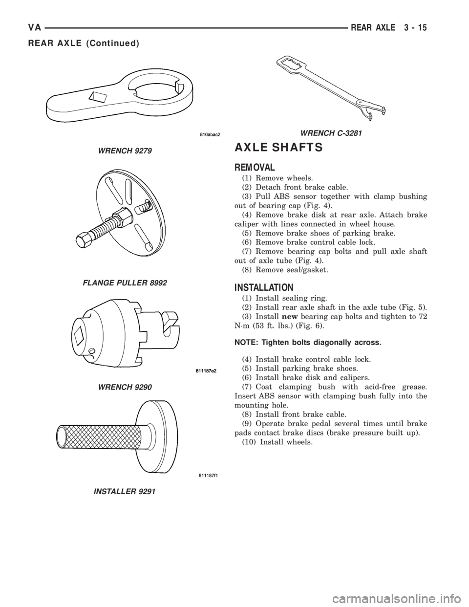
WRENCH 9290
INSTALLER 9291
WRENCH C-3281
VAREAR AXLE 3 - 15
REAR AXLE (Continued)
Page 60 of 1232
(2) Slide axle shaft into axle tube.
(3) Install axle shaft hub nuts and tighten to N´m
65 (48 ft. lbs.).
(4) Install wheels.
AXLE HUB BEARINGS/SEALS
REMOVAL
(1) Remove brake caliper with support.
(2) Remove axle shaft.
(3) Back-off parking brakes.
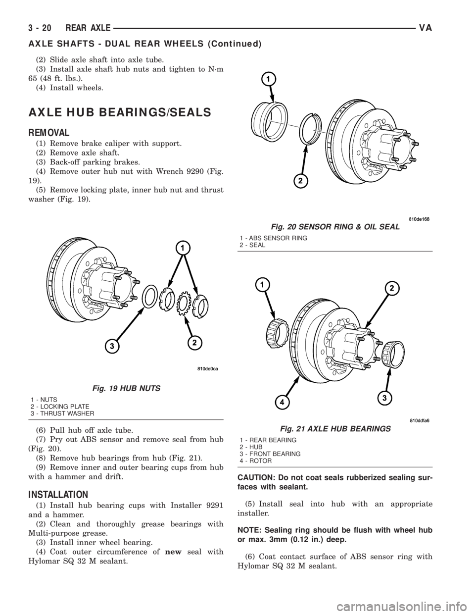
(4) Remove outer hub nut with Wrench 9290 (Fig.
19).
(5) Remove locking plate, inner hub nut and thrust
washer (Fig. 19).
(6) Pull hub off axle tube.
(7) Pry out ABS sensor and remove seal from hub
(Fig. 20).
(8) Remove hub bearings from hub (Fig. 21).
(9) Remove inner and outer bearing cups from hub
with a hammer and drift.
INSTALLATION
(1) Install hub bearing cups with Installer 9291
and a hammer.
(2) Clean and thoroughly grease bearings with
Multi-purpose grease.
(3) Install inner wheel bearing.
(4) Coat outer circumference ofnewseal with
Hylomar SQ 32 M sealant.CAUTION: Do not coat seals rubberized sealing sur-
faces with sealant.
(5) Install seal into hub with an appropriate
installer.
NOTE: Sealing ring should be flush with wheel hub
or max. 3mm (0.12 in.) deep.
(6) Coat contact surface of ABS sensor ring with
Hylomar SQ 32 M sealant.
Fig. 19 HUB NUTS
1 - NUTS
2 - LOCKING PLATE
3 - THRUST WASHER
Fig. 20 SENSOR RING & OIL SEAL
1 - ABS SENSOR RING
2 - SEAL
Fig. 21 AXLE HUB BEARINGS
1 - REAR BEARING
2 - HUB
3 - FRONT BEARING
4 - ROTOR
3 - 20 REAR AXLEVA
AXLE SHAFTS - DUAL REAR WHEELS (Continued)
Page 61 of 1232
(7) Drive ABS sensor ring ring in as far as the
stop with a plastic hammer.
(8) Install hub on axle tube.
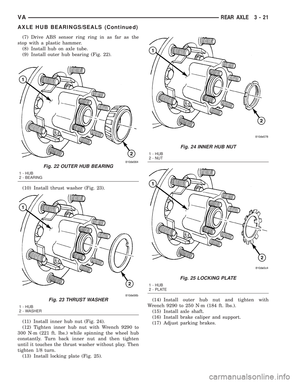
(9) Install outer hub bearing (Fig. 22).
(10) Install thrust washer (Fig. 23).
(11) Install inner hub nut (Fig. 24).
(12) Tighten inner hub nut with Wrench 9290 to
300 N´m (221 ft. lbs.) while spinning the wheel hub
constantly. Turn back inner nut and then tighten
until it touches the thrust washer without play. Then
tighten 1/8 turn.
(13) Install locking plate (Fig. 25).(14) Install outer hub nut and tighten with
Wrench 9290 to 250 N´m (184 ft. lbs.).
(15) Install axle shaft.
(16) Install brake caliper and support.
(17) Adjust parking brakes.
Fig. 22 OUTER HUB BEARING
1 - HUB
2 - BEARING
Fig. 23 THRUST WASHER
1 - HUB
2 - WASHER
Fig. 24 INNER HUB NUT
1 - HUB
2 - NUT
Fig. 25 LOCKING PLATE
1 - HUB
2 - PLATE
VAREAR AXLE 3 - 21
AXLE HUB BEARINGS/SEALS (Continued)
Page 63 of 1232
(9) Unscrew the marked nut.
(10) Reattach retainer wrench to joint flange.
(11) Screw onnewcollared nut and tighten care-
fully in stages until the previously value of torque to
rotate is exceeded by 0.5 N´m. (4.4 in. lbs.).
CAUTION: The total friction moment must not be
obtained by slackening the collared nut. Avoid over-
tightening the collared nut otherwise the compres-
sion ring inside will be compressed and will have to
be replaced. This requires total disassembly of the
gear set.
(12) Cut the collar of the tightened collared nut
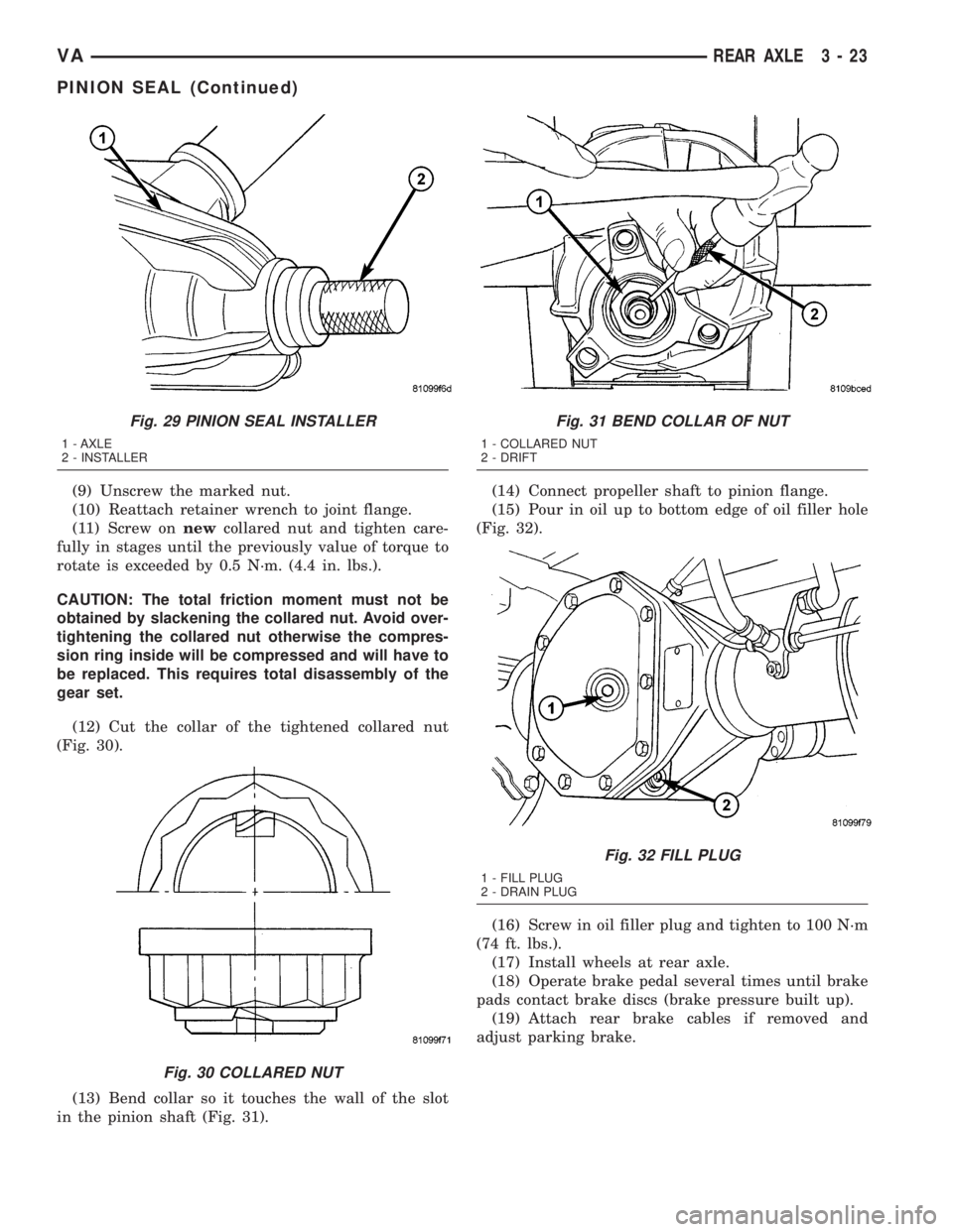
(Fig. 30).
(13) Bend collar so it touches the wall of the slot
in the pinion shaft (Fig. 31).(14) Connect propeller shaft to pinion flange.
(15) Pour in oil up to bottom edge of oil filler hole
(Fig. 32).
(16) Screw in oil filler plug and tighten to 100 N´m
(74 ft. lbs.).
(17) Install wheels at rear axle.
(18) Operate brake pedal several times until brake
pads contact brake discs (brake pressure built up).
(19) Attach rear brake cables if removed and
adjust parking brake.
Fig. 29 PINION SEAL INSTALLER
1 - AXLE
2 - INSTALLER
Fig. 30 COLLARED NUT
Fig. 31 BEND COLLAR OF NUT
1 - COLLARED NUT
2 - DRIFT
Fig. 32 FILL PLUG
1 - FILL PLUG
2 - DRAIN PLUG
VAREAR AXLE 3 - 23
PINION SEAL (Continued)