2005 MERCEDES-BENZ SPRINTER engine cover bolt
[x] Cancel search: engine cover boltPage 50 of 1232
REAR AXLE
TABLE OF CONTENTS
page page
REAR AXLE
DESCRIPTION.........................10
OPERATION...........................10
DIAGNOSIS AND TESTING................10
STANDARD PROCEDURE - DRAIN AND FILL . . 11
REMOVAL.............................11
INSTALLATION.........................12
SPECIFICATIONS.......................13
SPECIAL TOOLS.......................14
AXLE SHAFTS
REMOVAL.............................15
INSTALLATION.........................15AXLE BEARINGS/SEALS
REMOVAL.............................17
INSTALLATION.........................17
AXLE SHAFTS - DUAL REAR WHEELS
REMOVAL.............................19
INSTALLATION.........................19
AXLE HUB BEARINGS/SEALS
REMOVAL.............................20
INSTALLATION.........................20
PINION SEAL
REMOVAL.............................22
INSTALLATION.........................22
REAR AXLE
DESCRIPTION
The axle housings consist of a cast iron center sec-
tion with axle tubes extending from either side. The
tubes are pressed into and welded to the differential
housing to form a one-piece axle housing. The SRW
axle has semi-floating axle shafts, DRW has full-
floating axle shafts.
NOTE: Axle seals, axle bearings, pinion seal and
differential cover are the only serviceble compo-
nents. If differential is damaged/noisy the axle must
be replaced.
OPERATION
The axle receives power from the transmission
through the rear propeller shaft. The rear propeller
shaft is connected to the pinion gear which rotates
the differential through the gear mesh with the ring
gear bolted to the differential case. The engine power
is transmitted to the axle shafts through the pinion
mate and side gears. The side gears are splined to
the axle shafts.
DIAGNOSIS AND TESTING
NOTE: Axle seals, axle bearings, pinion seals and
differential cover are the only serviceble compo-
nents. If differential is damaged/noisy the axle must
be replaced.
GEAR NOISE
Axle gear noise can be caused by insufficient lubri-
cant, incorrect backlash, incorrect pinion depth, tooth
contact, worn/damaged gears, or the carrier housing
not having the proper offset and squareness.
Gear noise usually happens at a specific speed
range. The noise can also occur during a specific type
of driving condition. These conditions are accelera-
tion, deceleration, coast, or constant load.
When road testing, first warm-up the axle fluid by
driving the vehicle at least 5 miles and then acceler-
ate the vehicle to the speed range where the noise is
the greatest. Shift out-of-gear and coast through the
peak-noise range. If the noise stops or changes
greatly:
²Check for insufficient lubricant.
²Incorrect ring gear backlash.
²Gear damage.
Differential side gears and pinions can be checked
by turning the vehicle. They usually do not cause
noise during straight-ahead driving when the gears
are unloaded. The side gears are loaded during vehi-
cle turns. A worn pinion shaft can also cause a snap-
ping or a knocking noise.
BEARING NOISE
The axle shaft, differential and pinion bearings can
all produce noise when worn or damaged. Bearing
noise can be either a whining, or a growling sound.
Pinion bearingshave a constant-pitch noise. This
noise changes only with vehicle speed. Pinion bearing
noise will be higher pitched because it rotates at a
faster rate. Drive the vehicle and load the differen-
tial. If bearing noise occurs, the rear pinion bearing
is the source of the noise. If the bearing noise is
3 - 10 REAR AXLEVA
Page 146 of 1232
GENERATOR
DESCRIPTION
The generator is belt-driven by the engine using a
serpentine-type drive belt. It is serviced only as a
complete assembly. If the generator fails for any rea-
son, the entire assembly must be replaced.
On certain engines, the decoupler pulley may be
replaced separately.
OPERATION
As the energized rotor begins to rotate within the
generator, the spinning magnetic field induces a cur-
rent into the windings of the stator coil. Once the
generator begins producing sufficient current, it also
provides the current needed to energize the rotor.
The stator winding connections deliver the induced
AC current to 3 positive and 3 negative diodes for
rectification. From the diodes, rectified DC current is
delivered to the vehicle electrical system through the
generator battery terminal.
Although the generators appear the same exter-
nally, different generators with different output rat-
ings are used on this vehicle. Be certain that the
replacement generator has the same output rating
and part number as the original unit. Refer to Spec-
ifications and see Generator Ratings for amperage
ratings and part numbers.
Noise emitting from the generator may be caused
by: worn, loose or defective bearings; a loose or defec-
tive drive pulley (decoupler pulley); incorrect, worn,
damaged or misadjusted fan drive belt; loose mount-
ing bolts; a misaligned drive pulley or a defective sta-
tor or diode.
An instrument panel mounted, battery charge indi-
cator lamp is used. When the key is in the on posi-
tion, the lamp will be illuminated. This is done as a
bulb check. If this lamp remains illuminated while
the engine is running, a Diagnostic Trouble Code
(DTC) has been detected for the charging system.
REMOVAL
CAUTION: DISCONNECT NEGATIVE CABLE FROM
BATTERY BEFORE REMOVING BATTERY OUTPUT
WIRE FROM GENERATOR. FAILURE TO DO SO
CAN RESULT IN INJURY.
CAUTION: Never force a belt over a pulley rim
using a screwdriver. The synthetic fiber of the belt
can be damaged.
CAUTION: When installing a serpentine accessory
drive belt, the belt MUST be routed correctly. The
water pump will be rotating in the wrong direction ifthe belt is installed incorrectly, causing the engine
to overheat. Refer to belt routing label in engine
compartment, or refer to Belt Schematics in Cooling
System.
(1) Disconnect and isolate negative battery cable.
(2) Remove generator drive belt. Refer to Cooling
System for procedure.
(3) Raise and support vehicle.
(4) Remove protective plastic cover from B+ stud
at top of generator.
(5) Remove nut securing battery output cable to
B+ terminal at top of generator.
(6) Unplug field terminal connector at rear of gen-
erator.
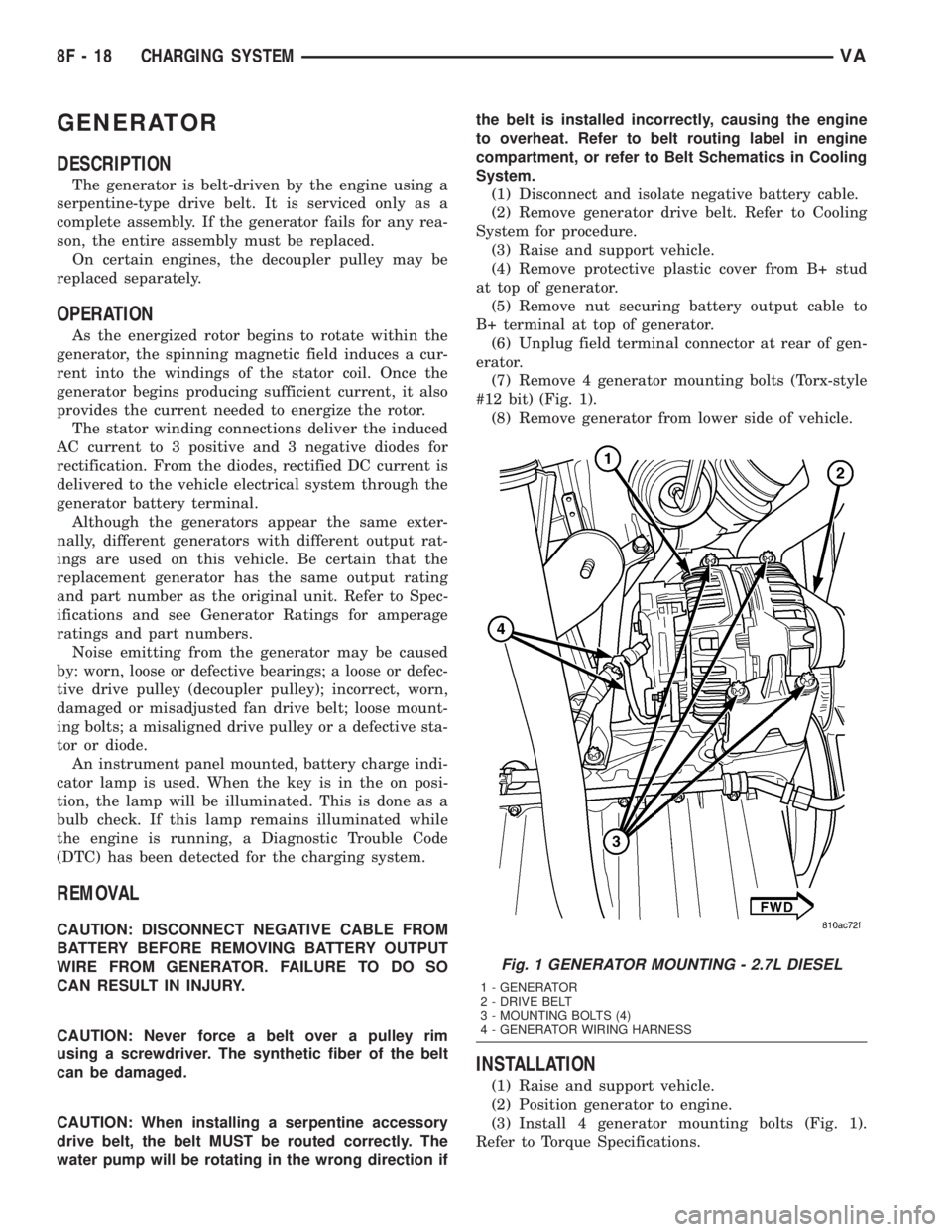
(7) Remove 4 generator mounting bolts (Torx-style
#12 bit) (Fig. 1).
(8) Remove generator from lower side of vehicle.
INSTALLATION
(1) Raise and support vehicle.
(2) Position generator to engine.
(3) Install 4 generator mounting bolts (Fig. 1).
Refer to Torque Specifications.
Fig. 1 GENERATOR MOUNTING - 2.7L DIESEL
1 - GENERATOR
2 - DRIVE BELT
3 - MOUNTING BOLTS (4)
4 - GENERATOR WIRING HARNESS
8F - 18 CHARGING SYSTEMVA
Page 739 of 1232
ENGINE
TABLE OF CONTENTS
page page
ENGINE
DESCRIPTION..........................2
STANDARD PROCEDURE
STANDARD PROCEDURE - COMPRESSION
TESTING ENGINE......................3
STANDARD PROCEDURE - CYLINDER
LEAK DOWN TEST.....................3
STANDARD PROCEDURE - DETERMINING
CYLINDER PRESSURE LOSS.............4
REMOVAL
REMOVAL - ENGINE COVER.............4
REMOVAL............................4
INSTALLATION
INSTALLATION - ENGINE COVER..........7
INSTALLATION........................7
SPECIFICATIONS - TORQUE
SPECIFICATIONS......................8
SPECIAL TOOLS.......................14
AIR CLEANER ELEMENT
REMOVAL.............................20
INSTALLATION.........................20
AIR CLEANER HOUSING
REMOVAL.............................20
INSTALLATION.........................20
CYLINDER HEAD
STANDARD PROCEDURE
STANDARD PROCEDURE - CYLINDER
HEAD BOLT INSPECTION...............21
STANDARD PROCEDURE - MEASURE
CYLINDER HEAD SURFACE.............21
REMOVAL
REMOVAL - CYLINDER HEAD............22
REMOVAL - CYLINDER HEAD FRONT
COVER.............................23
REMOVAL - CYLINDER HEAD GUIDE RAIL . . 24
INSTALLATION
INSTALLATION - CYLINDER HEAD........25
INSTALLATION - CYLINDER HEAD FRONT
COVER.............................26
INSTALLATION - CYLINDER HEAD GUIDE
RAIL...............................26
CAMSHAFT(S)
STANDARD PROCEDURE - CHECKING
CAMSHAFT POSITION.................27
REMOVAL.............................28
INSTALLATION.........................29
CYLINDER HEAD COVER(S)
REMOVAL.............................30
INSTALLATION.........................30VALVE SPRINGS
REMOVAL
REMOVAL - VALVE SPRINGS............31
REMOVAL - VALVES...................31
INSTALLATION
INSTALLATION - VALVE SPRINGS........32
INSTALLATION - VALVES...............33
ENGINE BLOCK
STANDARD PROCEDURE
STANDARD PROCEDURE - REPLACING
ENGINE CORE AND OIL GALLERY PLUGS . . 34
STANDARD PROCEDURE - MEASURING
CYLINDER BORES....................34
CRANKSHAFT
STANDARD PROCEDURE - MEASURE
CRANKSHAFT AND BLOCK JOURNALS....35
REMOVAL.............................35
INSTALLATION.........................36
CRANKSHAFT OIL SEAL - REAR
REMOVAL.............................37
INSTALLATION.........................37
CRANKSHAFT OIL SEAL - FRONT
REMOVAL.............................38
INSTALLATION.........................38
FLYWHEEL
REMOVAL.............................39
INSTALLATION
INSTALLATION.......................39
INSTALLATION.......................39
PISTON & CONNECTING ROD
DESCRIPTION.........................40
STANDARD PROCEDURE
STANDARD PROCEDURE - CHECKING AND
REPAIRING CONNECTING RODS.........40
STANDARD PROCEDURE - MEASURING
PISTON PROTRUSION.................42
REMOVAL.............................42
INSTALLATION.........................43
PISTON RINGS
STANDARD PROCEDURE - PISTON RING
FITTING.............................46
VIBRATION DAMPER
REMOVAL.............................47
INSTALLATION.........................48
VACUUM PUMP
DESCRIPTION.........................48
OPERATION...........................48
REMOVAL.............................48
INSTALLATION.........................49
VAENGINE 9 - 1
Page 745 of 1232
INSTALLATION
INSTALLATION - ENGINE COVER
(1) Align cover and install screws. tighten screws
to 11N´m (97 lbs. in.) (Fig. 2).
INSTALLATION
NOTE: Deburr and seal metal from cross plate
removal with anti corrosion material.
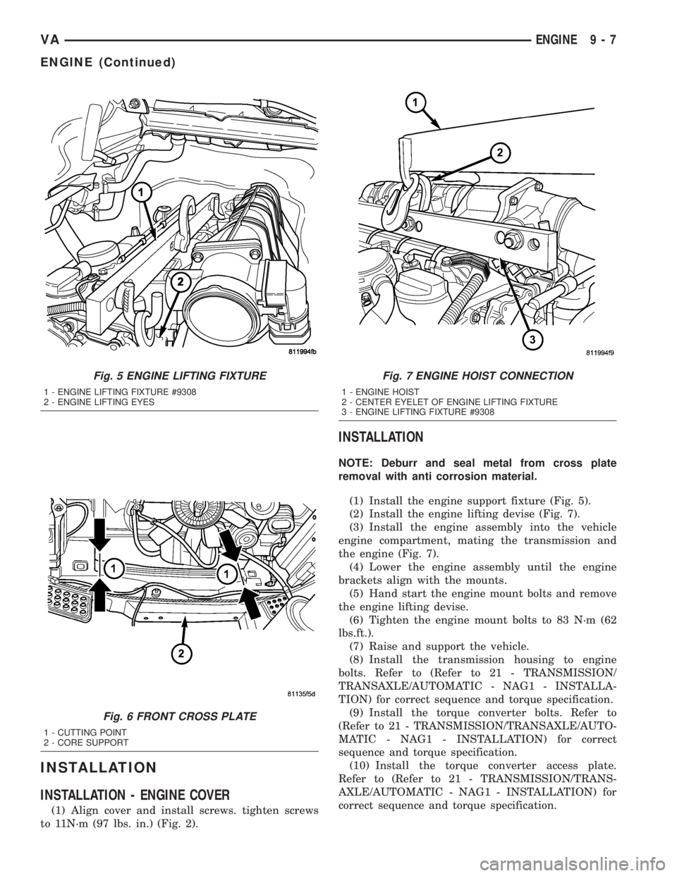
(1) Install the engine support fixture (Fig. 5).
(2) Install the engine lifting devise (Fig. 7).
(3) Install the engine assembly into the vehicle
engine compartment, mating the transmission and
the engine (Fig. 7).
(4) Lower the engine assembly until the engine
brackets align with the mounts.
(5) Hand start the engine mount bolts and remove
the engine lifting devise.
(6) Tighten the engine mount bolts to 83 N´m (62
lbs.ft.).
(7) Raise and support the vehicle.
(8) Install the transmission housing to engine
bolts. Refer to (Refer to 21 - TRANSMISSION/
TRANSAXLE/AUTOMATIC - NAG1 - INSTALLA-
TION) for correct sequence and torque specification.
(9) Install the torque converter bolts. Refer to
(Refer to 21 - TRANSMISSION/TRANSAXLE/AUTO-
MATIC - NAG1 - INSTALLATION) for correct
sequence and torque specification.
(10) Install the torque converter access plate.
Refer to (Refer to 21 - TRANSMISSION/TRANS-
AXLE/AUTOMATIC - NAG1 - INSTALLATION) for
correct sequence and torque specification.
Fig. 5 ENGINE LIFTING FIXTURE
1 - ENGINE LIFTING FIXTURE #9308
2 - ENGINE LIFTING EYES
Fig. 6 FRONT CROSS PLATE
1 - CUTTING POINT
2 - CORE SUPPORT
Fig. 7 ENGINE HOIST CONNECTION
1 - ENGINE HOIST
2 - CENTER EYELET OF ENGINE LIFTING FIXTURE
3 - ENGINE LIFTING FIXTURE #9308
VAENGINE 9 - 7
ENGINE (Continued)
Page 746 of 1232
(11) Install the transmission cooler lines to trans-
mission.(Refer to 21 - TRANSMISSION/TRANS-
AXLE/AUTOMATIC - NAG1 - INSTALLATION) for
correct sequence and torque specification.
(12) Install transmission electrical connector and
shifter hardware.Refer to (Refer to 21 - TRANSMIS-
SION/TRANSAXLE/AUTOMATIC - NAG1 - INSTAL-
LATION) for correct sequence and torque
specification.
(13) Install the steering gear and tighten in two
stages. 25 N´m (18.5 lbs. ft.), then 45 N´m (33 lbs. ft.)
plus 90É.
(14) Install the crank sensor.
(15) Install the starter.
(16) Connect the ground strap (left side).
(17) Align and install the exhaust and bracket
(Refer to 11 - EXHAUST SYSTEM/EXHAUST PIPE -
INSTALLATION).
(18) Lower the vehicle.
(19) Install the air inlet hose at the turbocharger
(Fig. 3).
(20) Connect the vacuum hose at the turbocharger
(Fig. 3).
(21) Connect the coolant supply and return hoses
(Fig. 3).(22) Connect the brake booster vacuum hose at the
vacuum pump (Fig. 3).
(23) Connect the refrigerant lines (Fig. 3).
(24) Connect the fuel lines at the filter assembly
(Fig. 3).
(25) Connect the power steering hoses (Fig. 3).
(26) Install the radiator/charge air cooler and
hose(s) assemblies (Refer to 7 - COOLING/ENGINE/
RADIATOR - INSTALLATION).
(27) Install A/C condenser.
(28) Install air cleaner housing, sensors, and hoses
(Refer to 9 - ENGINE/AIR INTAKE SYSTEM/AIR
CLEANER HOUSING - INSTALLATION).
(29) Route the engine wiring harness inside the
vehicle and connect.
(30) Install the front grill assembly.
(31) Install and align the hood.
(32) Connect the negative battery cable.
(33) Check and fill engine oil.
(34) Fill cooling system to proper level with the
appropriate coolant.
(35) Evacuate and recharge air conditioning.
(36) Check and refill all ancillary system fluid lev-
els.
(37) Start engine and inspect for leaks.
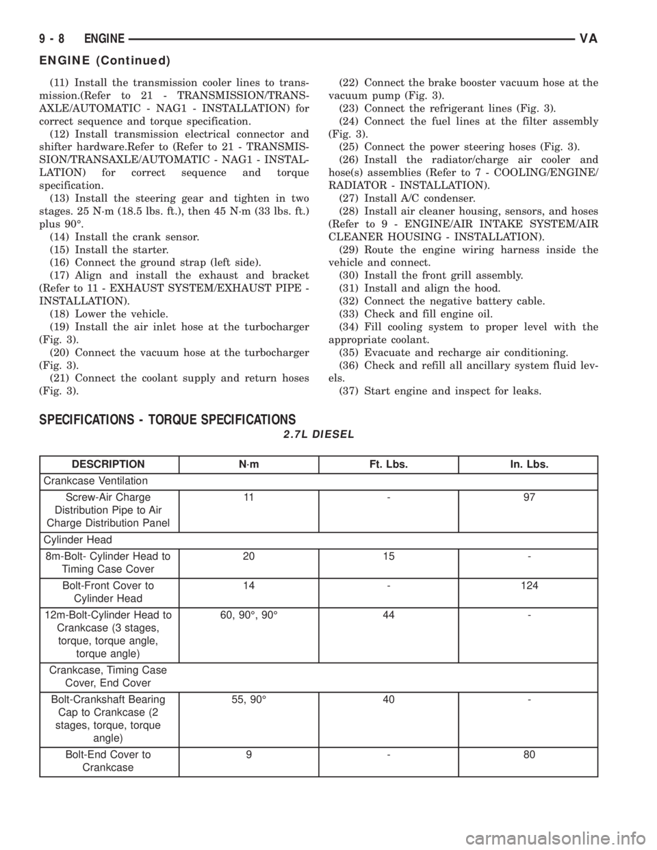
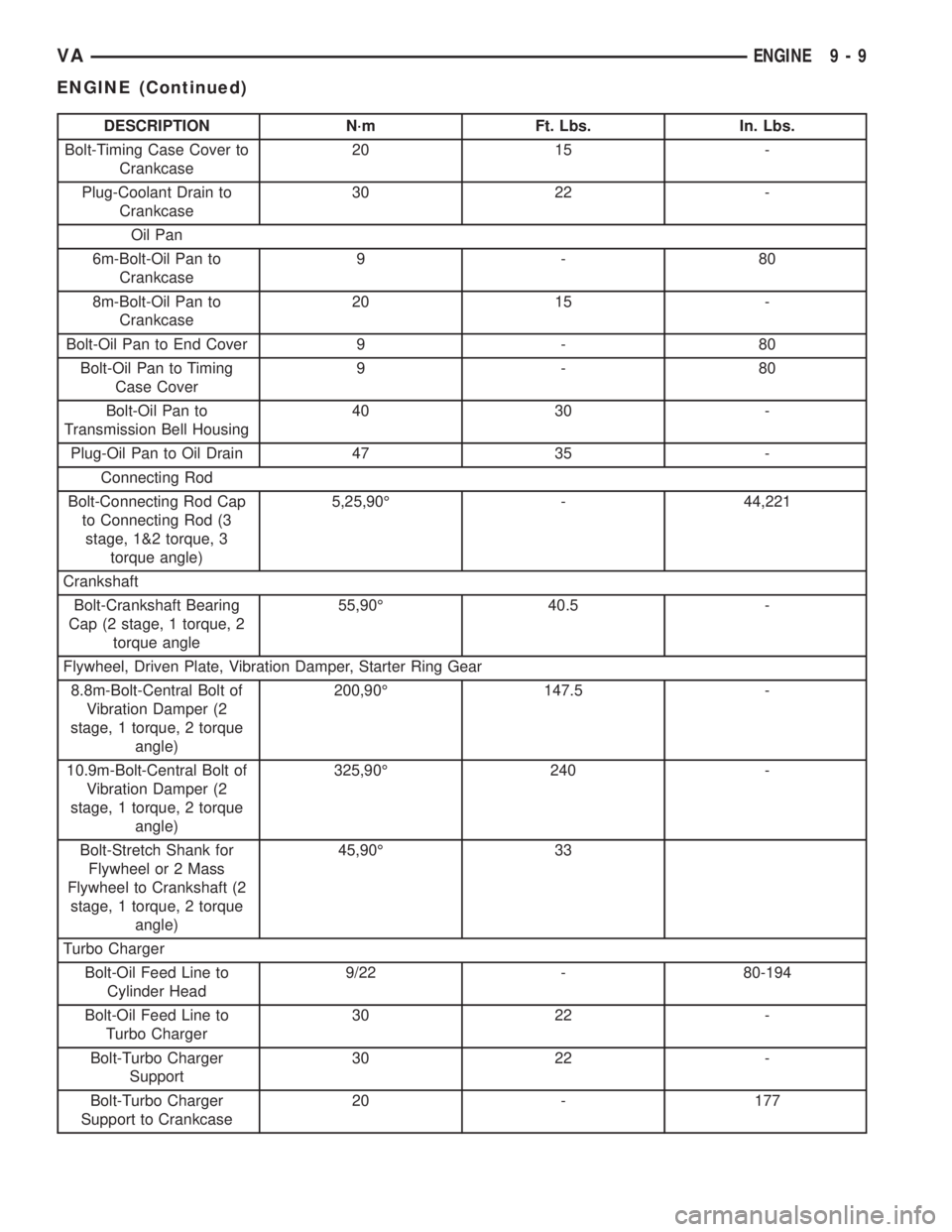
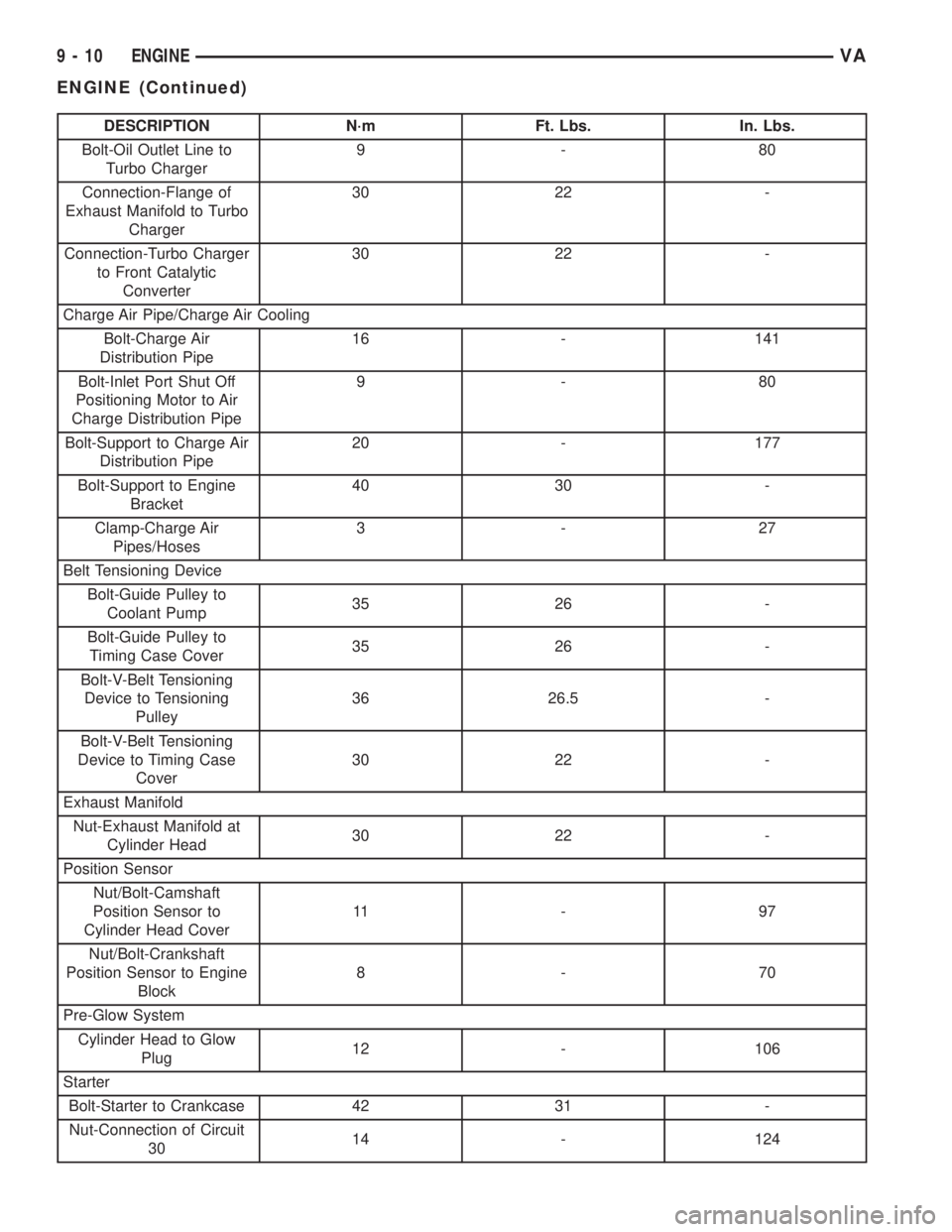
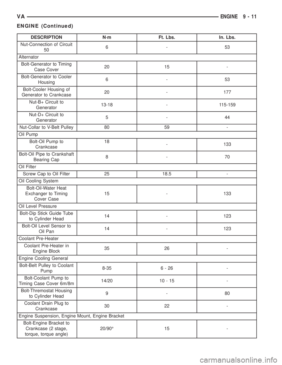
SPECIFICATIONS - TORQUE SPECIFICATIONS
2.7L DIESEL
DESCRIPTION N´m Ft. Lbs. In. Lbs.
Crankcase Ventilation
Screw-Air Charge
Distribution Pipe to Air
Charge Distribution Panel11 - 9 7
Cylinder Head
8m-Bolt- Cylinder Head to
Timing Case Cover20 15 -
Bolt-Front Cover to
Cylinder Head14 - 124
12m-Bolt-Cylinder Head to
Crankcase (3 stages,
torque, torque angle,
torque angle)60, 90É, 90É 44 -
Crankcase, Timing Case
Cover, End Cover
Bolt-Crankshaft Bearing
Cap to Crankcase (2
stages, torque, torque
angle)55, 90É 40 -
Bolt-End Cover to
Crankcase9-80
9 - 8 ENGINEVA
ENGINE (Continued)
Page 747 of 1232
DESCRIPTION N´m Ft. Lbs. In. Lbs.
Bolt-Timing Case Cover to
Crankcase20 15 -
Plug-Coolant Drain to
Crankcase30 22 -
Oil Pan
6m-Bolt-Oil Pan to
Crankcase9-80
8m-Bolt-Oil Pan to
Crankcase20 15 -
Bolt-Oil Pan to End Cover 9 - 80
Bolt-Oil Pan to Timing
Case Cover9-80
Bolt-Oil Pan to
Transmission Bell Housing40 30 -
Plug-Oil Pan to Oil Drain 47 35 -
Connecting Rod
Bolt-Connecting Rod Cap
to Connecting Rod (3
stage, 1&2 torque, 3
torque angle)5,25,90É - 44,221
Crankshaft
Bolt-Crankshaft Bearing
Cap (2 stage, 1 torque, 2
torque angle55,90É 40.5 -
Flywheel, Driven Plate, Vibration Damper, Starter Ring Gear
8.8m-Bolt-Central Bolt of
Vibration Damper (2
stage, 1 torque, 2 torque
angle)200,90É 147.5 -
10.9m-Bolt-Central Bolt of
Vibration Damper (2
stage, 1 torque, 2 torque
angle)325,90É 240 -
Bolt-Stretch Shank for
Flywheel or 2 Mass
Flywheel to Crankshaft (2
stage, 1 torque, 2 torque
angle)45,90É 33
Turbo Charger
Bolt-Oil Feed Line to
Cylinder Head9/22 - 80-194
Bolt-Oil Feed Line to
Turbo Charger30 22 -
Bolt-Turbo Charger
Support30 22 -
Bolt-Turbo Charger
Support to Crankcase20 - 177
VAENGINE 9 - 9
ENGINE (Continued)
Page 748 of 1232
DESCRIPTION N´m Ft. Lbs. In. Lbs.
Bolt-Oil Outlet Line to
Turbo Charger9-80
Connection-Flange of
Exhaust Manifold to Turbo
Charger30 22 -
Connection-Turbo Charger
to Front Catalytic
Converter30 22 -
Charge Air Pipe/Charge Air Cooling
Bolt-Charge Air
Distribution Pipe16 - 141
Bolt-Inlet Port Shut Off
Positioning Motor to Air
Charge Distribution Pipe9-80
Bolt-Support to Charge Air
Distribution Pipe20 - 177
Bolt-Support to Engine
Bracket40 30 -
Clamp-Charge Air
Pipes/Hoses3-27
Belt Tensioning Device
Bolt-Guide Pulley to
Coolant Pump35 26 -
Bolt-Guide Pulley to
Timing Case Cover35 26 -
Bolt-V-Belt Tensioning
Device to Tensioning
Pulley36 26.5 -
Bolt-V-Belt Tensioning
Device to Timing Case
Cover30 22 -
Exhaust Manifold
Nut-Exhaust Manifold at
Cylinder Head30 22 -
Position Sensor
Nut/Bolt-Camshaft
Position Sensor to
Cylinder Head Cover11 - 9 7
Nut/Bolt-Crankshaft
Position Sensor to Engine
Block8-70
Pre-Glow System
Cylinder Head to Glow
Plug12 - 106
Starter
Bolt-Starter to Crankcase 42 31 -
Nut-Connection of Circuit
3014 - 124
9 - 10 ENGINEVA
ENGINE (Continued)
Page 749 of 1232
DESCRIPTION N´m Ft. Lbs. In. Lbs.
Nut-Connection of Circuit
506-53
Alternator
Bolt-Generator to Timing
Case Cover20 15 -
Bolt-Generator to Cooler
Housing6-53
Bolt-Cooler Housing of
Generator to Crankcase20 - 177
Nut-B+ Circuit to
Generator13-18 - 115-159
Nut-D+ Circuit to
Generator5-44
Nut-Collar to V-Belt Pulley 80 59 -
Oil Pump
Bolt-Oil Pump to
Crankcase18
- 133
Bolt-Oil Pipe to Crankshaft
Bearing Cap8-70
Oil Filter
Screw Cap to Oil Filter 25 18.5 -
Oil Cooling System
Bolt-Oil-Water Heat
Exchanger to Timing
Cover Case15 - 133
Oil Level Pressure
Bolt-Dip Stick Guide Tube
to Cylinder Head14 - 123
Bolt-Oil Level Sensor to
Oil Pan14 - 123
Coolant Pre-Heater
Coolant Pre-Heater in
Engine Block35 26 -
Engine Cooling General
Bolt-Belt Pulley to Coolant
Pump8-35 6 - 26 -
Bolt-Coolant Pump to
Timing Case Cover 6m/8m14/20 10 - 15 -
Bolt-Thremostat Housing
to Cylinder Head9-80
Coolant Drain Plug to
Crankcase30 22 -
Engine Suspension, Engine Mount, Engine Bracket
Bolt-Engine Bracket to
Crankcase (2 stage,
torque, torque angle)20/90É 15 -
VAENGINE 9 - 11
ENGINE (Continued)