2005 MERCEDES-BENZ SPRINTER lock
[x] Cancel search: lockPage 12 of 1232
engine to overheat because the specific heat of anti-
freeze is lower than that of water.
Use of 100 percent ethylene-glycol will cause for-
mation of additive deposits in the system, as the cor-
rosion inhibitive additives in ethylene-glycol require
the presence of water to dissolve. The deposits act as
insulation, causing temperatures to rise. The
increased temperature can result in engine detona-
tion. In addition, 100 percent ethylene-glycol freezes
at -22É C (-8É F ).
PROPYLENE-GLYCOL MIXTURES
It's overall effective temperature range is smaller
than that of ethylene-glycol. The freeze point of 50/50
propylene-glycol and water is -32É C (-26É F), 10É C
higher than ethylene-glycol's freeze point. The boiling
point (protection against summer boil-over) of propy-
lene-glycol is 125É C (257ÉF)at96.5 kPa (14 psi),
compared to 128É C (263É F) for ethylene-glycol. Pro-
pylene glycol also has slightly poorer heat transfer
characteristics than ethylene glycol. This can
increase cylinder head temperatures under certain
conditions.
Propylene-glycol/ethylene-glycol mixtures can cause
the destabilization of various corrosion inhibitors,
causing damage to the various cooling system compo-
nents. Also, once ethylene-glycol and propylene-glycol
based coolants are mixed in the vehicle, conventional
methods of determining freeze point will not be accu-
rate. Both the refractive index and specific gravity
differ between ethylene glycol and propylene glycol.
DESCRIPTION - HOAT COOLANT
WARNING: ANTIFREEZE IS AN ETHYLENE-GLYCOL
BASE COOLANT AND IS HARMFUL IF SWAL-
LOWED OR INHALED. IF SWALLOWED, DRINK
TWO GLASSES OF WATER AND INDUCE VOMIT-
ING. IF INHALED, MOVE TO FRESH AIR AREA.
SEEK MEDICAL ATTENTION IMMEDIATELY. DO NOT
STORE IN OPEN OR UNMARKED CONTAINERS.
WASH SKIN AND CLOTHING THOROUGHLY AFTER
COMING IN CONTACT WITH ETHYLENE-GLYCOL.
KEEP OUT OF REACH OF CHILDREN. DISPOSE OF
GLYCOL BASE COOLANT PROPERLY, CONTACT
YOUR DEALER OR GOVERNMENT AGENCY FOR
LOCATION OF COLLECTION CENTER IN YOUR
AREA. DO NOT OPEN A COOLING SYSTEM WHEN
THE ENGINE IS AT OPERATING TEMPERATURE OR
HOT UNDER PRESSURE, PERSONAL INJURY CAN
RESULT. AVOID RADIATOR COOLING FAN WHEN
ENGINE COMPARTMENT RELATED SERVICE IS
PERFORMED, PERSONAL INJURY CAN RESULT.CAUTION: Use of Propylene-Glycol based coolants
is not recommended, as they provide less freeze
protection and less corrosion protection.
The cooling system is designed around the coolant.
The coolant must accept heat from engine metal, in
the cylinder head area near the exhaust valves and
engine block. Then coolant carries the heat to the
radiator where the tube/fin radiator can transfer the
heat to the air.
The use of aluminum cylinder blocks, cylinder
heads, and water pumps requires special corrosion
protection. MopartAntifreeze/Coolant, 5
Year/100,000 Mile Formula (MS-9769), or the equiva-
lent ethylene-glycol base coolant with organic corro-
sion inhibitors (called HOAT, for Hybrid Organic
Additive Technology) is recommended. This coolant
offers the best engine cooling without corrosion when
mixed with 50% ethylene-glycol and 50% distilled
water to obtain a freeze point of -37ÉC (-34ÉF). If it
loses color or becomes contaminated, drain, flush,
and replace with fresh properly mixed coolant solu-
tion.
CAUTION: MoparTAntifreeze/Coolant, 5
Year/100,000 Mile Formula (MS-9769) may not be
mixed with any other type of antifreeze. Mixing of
coolants other than specified (non-HOAT), may
result in engine damage that may not be covered
under the new vehicle warranty, and decreased cor-
rosion protection.
COOLANT PERFORMANCE
The required ethylene-glycol (antifreeze) and water
mixture depends upon climate and vehicle operating
conditions. The coolant performance of various mix-
tures follows:
Pure Water-Water can absorb more heat than a
mixture of water and ethylene-glycol. This is for pur-
pose of heat transfer only. Water also freezes at a
higher temperature and allows corrosion.
100 percent Ethylene-Glycol-The corrosion
inhibiting additives in ethylene-glycol need the pres-
ence of water to dissolve. Without water, additives
form deposits in system. These act as insulation
causing temperature to rise. The increased tempera-
ture can result in engine detonation. In addition, 100
percent ethylene-glycol freezes at -22ÉC (-8ÉF).
50/50 Ethylene-Glycol and Water-Is the recom-
mended mixture, it provides protection against freez-
ing to -37ÉC (-34ÉF). The antifreeze concentration
must alwaysbe a minimum of 44 percent, year-
round in all climates. If percentage is lower, engine
parts may be eroded by cavitation. Maximum protec-
tion against freezing is provided with a 68 percent
antifreeze concentration, which prevents freezing
0 - 2 LUBRICATION & MAINTENANCEVA
FLUID TYPES (Continued)
Page 13 of 1232
down to -67.7ÉC (-90ÉF). A higher percentage will
freeze at a warmer temperature. Also, a higher per-
centage of antifreeze can cause the engine to over-
heat because specific heat of antifreeze is lower than
that of water.
CAUTION: Richer antifreeze mixtures cannot be
measured with normal field equipment and can
cause problems associated with 100 percent ethyl-
ene-glycol.
COOLANT SELECTION AND ADDITIVES
The use of aluminum cylinder blocks, cylinder
heads and water pumps requires special corrosion
protection. Only MopartAntifreeze/Coolant, 5
Year/100,000 Mile Formula (glycol base coolant with
corrosion inhibitors called HOAT, for Hybrid Organic
Additive Technology) is recommended. This coolant
offers the best engine cooling without corrosion when
mixed with 50% distilled water to obtain to obtain a
freeze point of -37ÉC (-34ÉF). If it loses color or
becomes contaminated, drain, flush, and replace with
fresh properly mixed coolant solution.
CAUTION: Do not use coolant additives that are
claimed to improve engine cooling.
DESCRIPTION - AXLE
NOTE: DaimlerChrysler recommends MoparTlubri-
cant or lubricant conforming to MS-8985.
REAR AXLE
²Synthetic Gear & Axle Lubricant SAE 75W-140
DESCRIPTION - BRAKE FLUID
NOTE: DaimlerChrysler recommends using DOT- 4
or equivalent brake fluid.
BRAKE FLUID
²DOT-4 or equivalent brake fluid.
DESCRIPTION - POWER STEERING FLUID
NOTE: DaimlerChrysler recommends using Mopar
ATF+4 Automatic Transmission fluid or equivalent.
POWER STEERING FLUID
²Mopar ATF+4 Automatic Transmission fluid or
equivalent.
DESCRIPTION - ENGINE OIL - DIESEL
ENGINES
SAE VISCOSITY GRADE
CAUTION: Low viscosity oils must have the proper
API quality.
The engine manufacturer strongly recommends the
use of synthetic engine oils, such as Mobilt1 SAE
0W-40.
We strongly recommend engine oils that meet the
requirements of the API Service Category CI-4 and
meet the requirements of Material Standard
MS-6395. Use Mopar or an equivalent oil meeting
the specification MS-6395.
Do not add any materials (other than leak detec-
tion dyes) to the engine oil. Engine oil is an engi-
neered product and it's performance may be impaired
by supplemental additives.
When topping off engine oil, only use oil of the
same quality grade and SAE classification.
The SAE class(viscosity)should be selected in
accordance with the average air temperature for the
season of the year.
The temperature limits given for the different SAE
classes should be regarded as guidelines which may
be exceeded temporarily to avoid excessively frequent
engine oil changes.
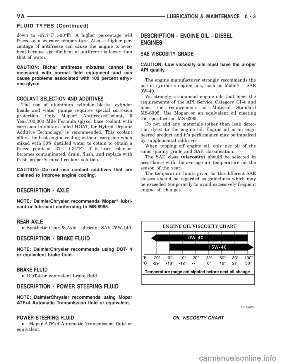
OIL VISCOSITY CHART
VALUBRICATION & MAINTENANCE 0 - 3
FLUID TYPES (Continued)
Page 16 of 1232
JUMP STARTING
STANDARD PROCEDURE - JUMP STARTING
WARNING: REVIEW ALL SAFETY PRECAUTIONS
AND WARNINGS IN THE BATTERY SYSTEM SEC-
TION OF THE SERVICE MANUAL. (Refer to 8 -
ELECTRICAL/BATTERY SYSTEM/BATTERY - STAN-
DARD PROCEDURE)
²DO NOT JUMP START A FROZEN BATTERY,
PERSONAL INJURY CAN RESULT.
²IF EQUIPPED, DO NOT JUMP START WHEN
MAINTENANCE FREE BATTERY INDICATOR DOT IS
YELLOW OR BRIGHT COLOR.
²DO NOT JUMP START A VEHICLE WHEN THE
BATTERY FLUID IS BELOW THE TOP OF LEAD
PLATES.
²DO NOT ALLOW JUMPER CABLE CLAMPS TO
TOUCH EACH OTHER WHEN CONNECTED TO A
BOOSTER SOURCE.
²DO NOT USE OPEN FLAME NEAR BATTERY.
²REMOVE METALLIC JEWELRY WORN ON
HANDS OR WRISTS TO AVOID INJURY BY ACCI-
DENTAL ARCING OF BATTERY CURRENT.
²WHEN USING A HIGH OUTPUT BOOSTING
DEVICE, DO NOT ALLOW BATTERY VOLTAGE TO
EXCEED 16 VOLTS. REFER TO INSTRUCTIONS
PROVIDED WITH DEVICE BEING USED.
FAILURE TO FOLLOW THESE INSTRUCTIONS MAY
RESULT IN PERSONAL INJURY.
CAUTION: When using another vehicle as a
booster, do not allow vehicles to touch. Electrical
systems can be damaged on either vehicle.
TO JUMP START A DISABLED VEHICLE:
(1) Raise hood on disabled vehicle and visually
inspect engine compartment for:
²Battery cable clamp condition, clean if necessary.
²Frozen battery.
²Yellow or bright color test indicator, if equipped.
²Low battery fluid level.
²Generator drive belt condition and tension.
²Fuel fumes or leakage, correct if necessary.
CAUTION: If the cause of starting problem on dis-
abled vehicle is severe, damage to booster vehicle
charging system can result.
(2) When using another vehicle as a booster
source, park the booster vehicle within cable reach.
Turn off all accessories, set the parking brake, place
the automatic transmission in PARK or the manual
transmission in NEUTRAL and turn the ignition
OFF.(3) On disabled vehicle, place gear selector in park
or neutral and set park brake. Turn off all accesso-
ries.
(4) Connect jumper cables to booster battery. RED
clamp to positive terminal (+). BLACK clamp to neg-
ative terminal (-). DO NOT allow clamps at opposite
end of cables to touch, electrical arc will result.
Review all warnings in this procedure.
(5) On disabled vehicle, connect RED jumper cable
clamp to positive (+) terminal. Connect BLACK
jumper cable clamp to engine ground as close to the
ground cable attaching point as possible.
(6) Start the engine in the vehicle which has the
booster battery, let the engine idle a few minutes,
then start the engine in the vehicle with the dis-
charged battery.
CAUTION: Do not crank starter motor on disabled
vehicle for more than 15 seconds, starter will over-
heat and could fail.
(7) Allow battery in disabled vehicle to charge to
at least 12.4 volts (75% charge) before attempting to
start engine. If engine does not start within 15 sec-
onds, stop cranking engine and allow starter to cool
(15 min.), before cranking again.
DISCONNECT CABLE CLAMPS AS FOLLOWS:
²Disconnect BLACK cable clamp from engine
ground on disabled vehicle.
²When using a Booster vehicle, disconnect
BLACK cable clamp from battery negative terminal.
Disconnect RED cable clamp from battery positive
terminal.
²Disconnect RED cable clamp from battery posi-
tive terminal on disabled vehicle.
TOWING
STANDARD PROCEDURE - TOWING
WARNING: Do not tow the vehicle if the key cannot
be turned in the ignition lock. If the key cannot be
turned, the ignition lock remains locked and the
vehicle cannot be steered. With the engine not run-
ning there is no power assistance for the braking
and steering systems. In this case, it is important to
keep in mind that a considerably higher degree of
effort is necessary to brake and steer the vehicle.
The vehicle must not be towed with the front axle
raised and the key in position 2 in the ignition lock
as the drive wheels could then lock due to the
acceleration skid control (ASR)
0 - 6 LUBRICATION & MAINTENANCEVA
Page 17 of 1232
If the Engine is Damaged
For towing distances up to 30 miles (about 50
km)
²Shift selector lever in ªNº position.
²Do not exceed a towing speed of 30 m.p.h. (50
km/h).
For towing distances greater than 30 mile
(about 50 km)
²Remove the propeller shafts leading to the drive
axles. The vehicle can be towed without restriction.
If the Transmission is Damaged
²Remove the propeller shafts leading to the drive
axles. The vehicle can be towed without restriction.
If the Front Axle is Damaged
²Raise the front axle.
²Observe the same towing restrictions as for
engine damage.
If the Rear Axle is Damaged
²Raise the rear axle.
NOTE: Comply with local legal regulations regard-
ing towing vehicles.
SAFETY PRECAUTIONS
NOTE: The following safety precautions must be
observed when towing a vehicle.
²Secure loose and protruding parts.
²Always use a safety chain system that is inde-
pendent of the lifting and towing equipment.
²Do not allow towing equipment to contact the
disabled vehicle's fuel tank.
²Do not allow anyone under the disabled vehicle
while it is lifted by the towing device.
²Do not allow passengers to ride in a vehicle
being towed.
²Always observe state and local laws regarding
towing regulations.
²Do not tow a vehicle in a manner that could
jeopardize the safety of the operator, pedestrians or
other motorists.
²Do not attach tow chains, T-hooks, J-hooks, or a
tow sling to a bumper, steering linkage, drive shafts
or a non-reinforced frame hole.
²Remove exhaust pipe tips that interfere with the
tow sling and crossbar
²Padding should be placed between the tow sling/
crossbar and any painted surfaces
²When placing tow hooks on the rear axle, posi-
tion them so they do not damage the brake tubing or
hoses²Do not tow the vehicle by connecting to the front
or rear shock absorbers
²Do not tow a heavily loaded vehicle. Damage to
the vehicle may result. Use a flatbed device to trans-
port a loaded vehicle.
GROUND CLEARANCE
CAUTION: If vehicle is towed with wheels removed,
install lug nuts to retain brake drums.
A towed vehicle should be raised until lifted wheels
are a minimum 100 mm (4 in) from the ground. Be
sure there is adequate ground clearance at the oppo-
site end of the vehicle, especially when towing over
rough terrain, steep rises in the road or if the vehicle
is equipped with air dams, spoilers, and/or ground
effect panels. If necessary, remove the wheels from
the lifted end of the vehicle and lower the vehicle
closer to the ground, to increase the ground clearance
at the opposite end of the vehicle. Install lug nuts on
wheel attaching studs to retain brake drums.
RAMP ANGLE
If a vehicle with flat-bed towing equipment is used,
the approach ramp angle should not exceed 15
degrees.
TOWING WHEN KEYS ARE NOT AVAILABLE
When the vehicle is locked and keys are not avail-
able, use a flat bed hauler. A Wheel-lift or Sling-type
device can be used provided all the wheels are lifted
off the ground using tow dollies.
MAINTENANCE SCHEDULES
DESCRIPTION
The use of Special lubricant additives is not recom-
mended. The use of such additives may affect the
warranty rights. With regard to legal stipulations
concerning emissions control, please note that
engines have to be serviced and adjusted in accor-
dance with special instructions and using special
measuring equipment. Modifications to or interfer-
ence with the emissions control systems are not per-
missible.
MAINTENANCE - WITHOUT ASSYST
MAINTENANCE COMPUTER
Maintenance Intervals
²Oil service ±Normal Operationevery 10,000
miles or 16,000 km or 12 months.
²Maintenance service every 20,000 miles or
32,000 km.
Additional work must be carried out at yearly
intervals.
VALUBRICATION & MAINTENANCE 0 - 7
TOWING (Continued)
Page 18 of 1232
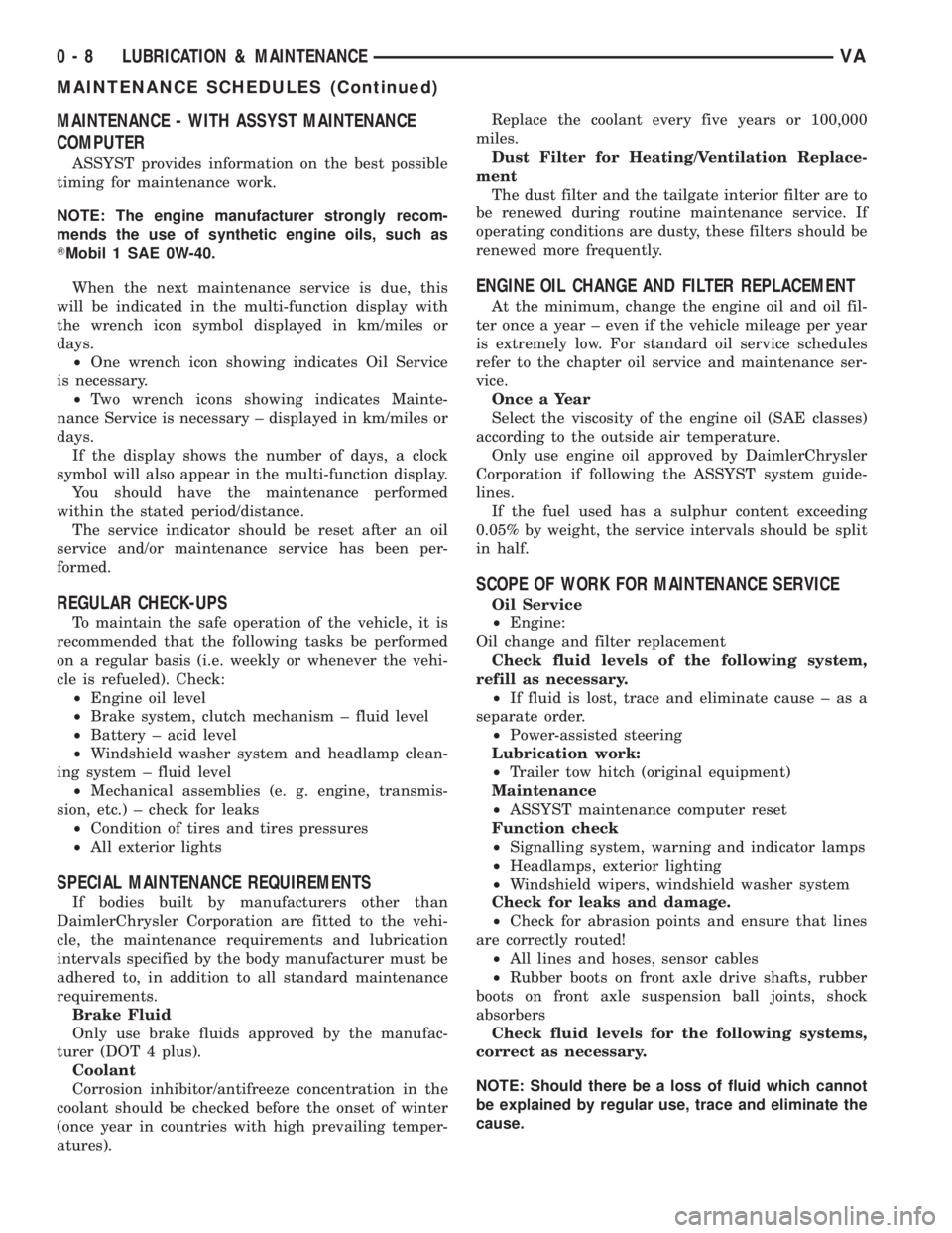
MAINTENANCE - WITH ASSYST MAINTENANCE
COMPUTER
ASSYST provides information on the best possible
timing for maintenance work.
NOTE: The engine manufacturer strongly recom-
mends the use of synthetic engine oils, such as
TMobil 1 SAE 0W-40.
When the next maintenance service is due, this
will be indicated in the multi-function display with
the wrench icon symbol displayed in km/miles or
days.
²One wrench icon showing indicates Oil Service
is necessary.
²Two wrench icons showing indicates Mainte-
nance Service is necessary ± displayed in km/miles or
days.
If the display shows the number of days, a clock
symbol will also appear in the multi-function display.
You should have the maintenance performed
within the stated period/distance.
The service indicator should be reset after an oil
service and/or maintenance service has been per-
formed.
REGULAR CHECK-UPS
To maintain the safe operation of the vehicle, it is
recommended that the following tasks be performed
on a regular basis (i.e. weekly or whenever the vehi-
cle is refueled). Check:
²Engine oil level
²Brake system, clutch mechanism ± fluid level
²Battery ± acid level
²Windshield washer system and headlamp clean-
ing system ± fluid level
²Mechanical assemblies (e. g. engine, transmis-
sion, etc.) ± check for leaks
²Condition of tires and tires pressures
²All exterior lights
SPECIAL MAINTENANCE REQUIREMENTS
If bodies built by manufacturers other than
DaimlerChrysler Corporation are fitted to the vehi-
cle, the maintenance requirements and lubrication
intervals specified by the body manufacturer must be
adhered to, in addition to all standard maintenance
requirements.
Brake Fluid
Only use brake fluids approved by the manufac-
turer (DOT 4 plus).
Coolant
Corrosion inhibitor/antifreeze concentration in the
coolant should be checked before the onset of winter
(once year in countries with high prevailing temper-
atures).Replace the coolant every five years or 100,000
miles.
Dust Filter for Heating/Ventilation Replace-
ment
The dust filter and the tailgate interior filter are to
be renewed during routine maintenance service. If
operating conditions are dusty, these filters should be
renewed more frequently.
ENGINE OIL CHANGE AND FILTER REPLACEMENT
At the minimum, change the engine oil and oil fil-
ter once a year ± even if the vehicle mileage per year
is extremely low. For standard oil service schedules
refer to the chapter oil service and maintenance ser-
vice.
Once a Year
Select the viscosity of the engine oil (SAE classes)
according to the outside air temperature.
Only use engine oil approved by DaimlerChrysler
Corporation if following the ASSYST system guide-
lines.
If the fuel used has a sulphur content exceeding
0.05% by weight, the service intervals should be split
in half.
SCOPE OF WORK FOR MAINTENANCE SERVICE
Oil Service
²Engine:
Oil change and filter replacement
Check fluid levels of the following system,
refill as necessary.
²If fluid is lost, trace and eliminate cause ± as a
separate order.
²Power-assisted steering
Lubrication work:
²Trailer tow hitch (original equipment)
Maintenance
²ASSYST maintenance computer reset
Function check
²Signalling system, warning and indicator lamps
²Headlamps, exterior lighting
²Windshield wipers, windshield washer system
Check for leaks and damage.
²Check for abrasion points and ensure that lines
are correctly routed!
²All lines and hoses, sensor cables
²Rubber boots on front axle drive shafts, rubber
boots on front axle suspension ball joints, shock
absorbers
Check fluid levels for the following systems,
correct as necessary.
NOTE: Should there be a loss of fluid which cannot
be explained by regular use, trace and eliminate the
cause.
0 - 8 LUBRICATION & MAINTENANCEVA
MAINTENANCE SCHEDULES (Continued)
Page 22 of 1232
FRONT
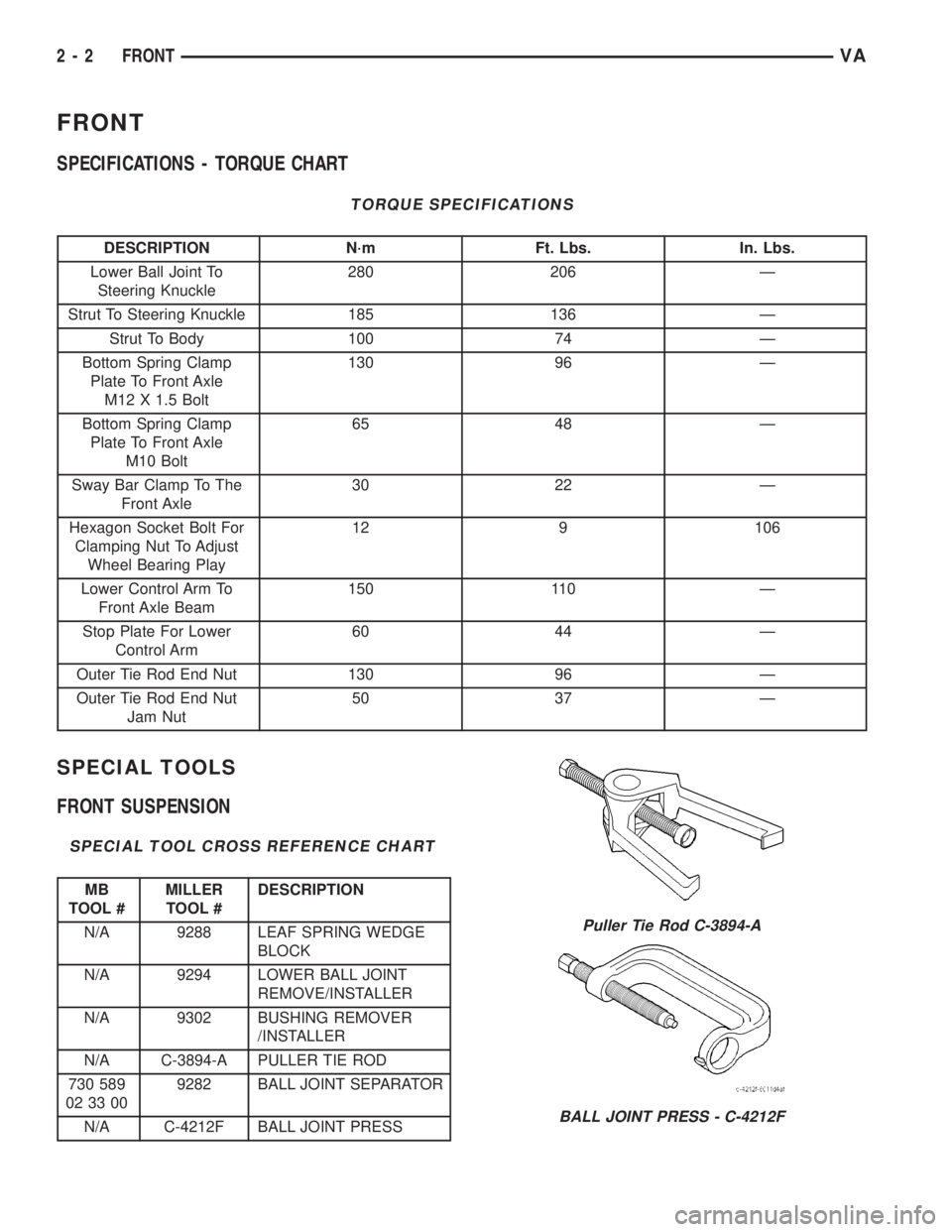
SPECIFICATIONS - TORQUE CHART
TORQUE SPECIFICATIONS
DESCRIPTION N´m Ft. Lbs. In. Lbs.
Lower Ball Joint To
Steering Knuckle280 206 Ð
Strut To Steering Knuckle 185 136 Ð
Strut To Body 100 74 Ð
Bottom Spring Clamp
Plate To Front Axle
M12 X 1.5 Bolt130 96 Ð
Bottom Spring Clamp
Plate To Front Axle
M10 Bolt65 48 Ð
Sway Bar Clamp To The
Front Axle30 22 Ð
Hexagon Socket Bolt For
Clamping Nut To Adjust
Wheel Bearing Play12 9 106
Lower Control Arm To
Front Axle Beam150 110 Ð
Stop Plate For Lower
Control Arm60 44 Ð
Outer Tie Rod End Nut 130 96 Ð
Outer Tie Rod End Nut
Jam Nut50 37 Ð
SPECIAL TOOLS
FRONT SUSPENSION
SPECIAL TOOL CROSS REFERENCE CHART
MB
TOOL #MILLER
TOOL #DESCRIPTION
N/A 9288 LEAF SPRING WEDGE
BLOCK
N/A 9294 LOWER BALL JOINT
REMOVE/INSTALLER
N/A 9302 BUSHING REMOVER
/INSTALLER
N/A C-3894-A PULLER TIE ROD
730 589
02 33 009282 BALL JOINT SEPARATOR
N/A C-4212F BALL JOINT PRESS
Puller Tie Rod C-3894-A
BALL JOINT PRESS - C-4212F
2 - 2 FRONTVA
Page 23 of 1232
BUSHINGS
REMOVAL
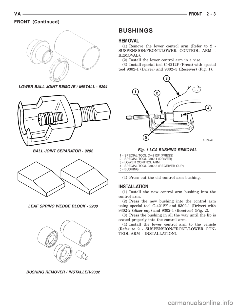
(1) Remove the lower control arm (Refer to 2 -
SUSPENSION/FRONT/LOWER CONTROL ARM -
REMOVAL).
(2) Install the lower control arm in a vise.
(3) Install special tool C-4212F (Press) with special
tool 9302-1 (Driver) and 9302±3 (Receiver) (Fig. 1).
(4) Press out the old control arm bushing.
INSTALLATION
(1) Install the new control arm bushing into the
control arm.
(2) Press the new bushing into the control arm
using special tool C-4212F and 9302-1 (Driver) with
9302-2 (Sizer cup) and 9302-4 (Receiver) (Fig. 2).
(3) Press the bushing in all the way until the lip is
seated properly into the control arm.
(4) Install the lower control arm to the vehicle
(Refer to 2 - SUSPENSION/FRONT/LOWER CON-
TROL ARM - INSTALLATION).
LOWER BALL JOINT REMOVE / INSTALL - 9294
BALL JOINT SEPARATOR - 9282
LEAF SPRING WEDGE BLOCK - 9288
BUSHING REMOVER / INSTALLER-9302
Fig. 1 LCA BUSHING REMOVAL
1 - SPECIAL TOOL C-4212F (PRESS)
2 - SPECIAL TOOL 9302-1 (DRIVER)
3 - LOWER CONTROL ARM
4 - SPECIAL TOOL 9302-3 (RECEIVER CUP)
5 - BUSHING
VAFRONT 2 - 3
FRONT (Continued)
Page 24 of 1232
HUB / BEARING
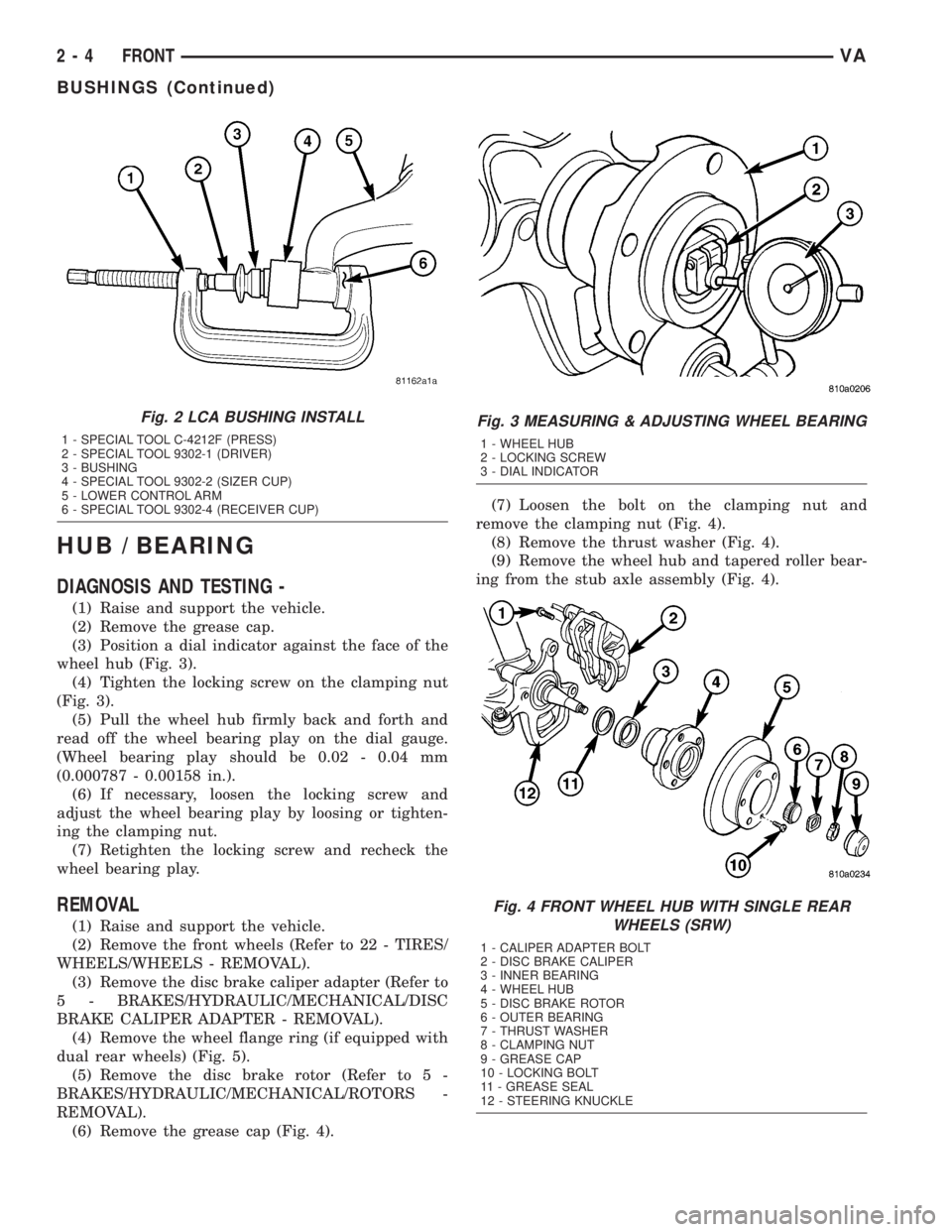
DIAGNOSIS AND TESTING -
(1) Raise and support the vehicle.
(2) Remove the grease cap.
(3) Position a dial indicator against the face of the
wheel hub (Fig. 3).
(4) Tighten the locking screw on the clamping nut
(Fig. 3).
(5) Pull the wheel hub firmly back and forth and
read off the wheel bearing play on the dial gauge.
(Wheel bearing play should be 0.02 - 0.04 mm
(0.000787 - 0.00158 in.).
(6) If necessary, loosen the locking screw and
adjust the wheel bearing play by loosing or tighten-
ing the clamping nut.
(7) Retighten the locking screw and recheck the
wheel bearing play.
REMOVAL
(1) Raise and support the vehicle.
(2) Remove the front wheels (Refer to 22 - TIRES/
WHEELS/WHEELS - REMOVAL).
(3) Remove the disc brake caliper adapter (Refer to
5 - BRAKES/HYDRAULIC/MECHANICAL/DISC
BRAKE CALIPER ADAPTER - REMOVAL).
(4) Remove the wheel flange ring (if equipped with
dual rear wheels) (Fig. 5).
(5) Remove the disc brake rotor (Refer to 5 -
BRAKES/HYDRAULIC/MECHANICAL/ROTORS -
REMOVAL).
(6) Remove the grease cap (Fig. 4).(7) Loosen the bolt on the clamping nut and
remove the clamping nut (Fig. 4).
(8) Remove the thrust washer (Fig. 4).
(9) Remove the wheel hub and tapered roller bear-
ing from the stub axle assembly (Fig. 4).
Fig. 2 LCA BUSHING INSTALL
1 - SPECIAL TOOL C-4212F (PRESS)
2 - SPECIAL TOOL 9302-1 (DRIVER)
3 - BUSHING
4 - SPECIAL TOOL 9302-2 (SIZER CUP)
5 - LOWER CONTROL ARM
6 - SPECIAL TOOL 9302-4 (RECEIVER CUP)
Fig. 3 MEASURING & ADJUSTING WHEEL BEARING
1 - WHEEL HUB
2 - LOCKING SCREW
3 - DIAL INDICATOR
Fig. 4 FRONT WHEEL HUB WITH SINGLE REAR
WHEELS (SRW)
1 - CALIPER ADAPTER BOLT
2 - DISC BRAKE CALIPER
3 - INNER BEARING
4 - WHEEL HUB
5 - DISC BRAKE ROTOR
6 - OUTER BEARING
7 - THRUST WASHER
8 - CLAMPING NUT
9 - GREASE CAP
10 - LOCKING BOLT
11 - GREASE SEAL
12 - STEERING KNUCKLE
2 - 4 FRONTVA
BUSHINGS (Continued)