2005 MERCEDES-BENZ SPRINTER park assist
[x] Cancel search: park assistPage 16 of 1232
JUMP STARTING
STANDARD PROCEDURE - JUMP STARTING
WARNING: REVIEW ALL SAFETY PRECAUTIONS
AND WARNINGS IN THE BATTERY SYSTEM SEC-
TION OF THE SERVICE MANUAL. (Refer to 8 -
ELECTRICAL/BATTERY SYSTEM/BATTERY - STAN-
DARD PROCEDURE)
²DO NOT JUMP START A FROZEN BATTERY,
PERSONAL INJURY CAN RESULT.
²IF EQUIPPED, DO NOT JUMP START WHEN
MAINTENANCE FREE BATTERY INDICATOR DOT IS
YELLOW OR BRIGHT COLOR.
²DO NOT JUMP START A VEHICLE WHEN THE
BATTERY FLUID IS BELOW THE TOP OF LEAD
PLATES.
²DO NOT ALLOW JUMPER CABLE CLAMPS TO
TOUCH EACH OTHER WHEN CONNECTED TO A
BOOSTER SOURCE.
²DO NOT USE OPEN FLAME NEAR BATTERY.
²REMOVE METALLIC JEWELRY WORN ON
HANDS OR WRISTS TO AVOID INJURY BY ACCI-
DENTAL ARCING OF BATTERY CURRENT.
²WHEN USING A HIGH OUTPUT BOOSTING
DEVICE, DO NOT ALLOW BATTERY VOLTAGE TO
EXCEED 16 VOLTS. REFER TO INSTRUCTIONS
PROVIDED WITH DEVICE BEING USED.
FAILURE TO FOLLOW THESE INSTRUCTIONS MAY
RESULT IN PERSONAL INJURY.
CAUTION: When using another vehicle as a
booster, do not allow vehicles to touch. Electrical
systems can be damaged on either vehicle.
TO JUMP START A DISABLED VEHICLE:
(1) Raise hood on disabled vehicle and visually
inspect engine compartment for:
²Battery cable clamp condition, clean if necessary.
²Frozen battery.
²Yellow or bright color test indicator, if equipped.
²Low battery fluid level.
²Generator drive belt condition and tension.
²Fuel fumes or leakage, correct if necessary.
CAUTION: If the cause of starting problem on dis-
abled vehicle is severe, damage to booster vehicle
charging system can result.
(2) When using another vehicle as a booster
source, park the booster vehicle within cable reach.
Turn off all accessories, set the parking brake, place
the automatic transmission in PARK or the manual
transmission in NEUTRAL and turn the ignition
OFF.(3) On disabled vehicle, place gear selector in park
or neutral and set park brake. Turn off all accesso-
ries.
(4) Connect jumper cables to booster battery. RED
clamp to positive terminal (+). BLACK clamp to neg-
ative terminal (-). DO NOT allow clamps at opposite
end of cables to touch, electrical arc will result.
Review all warnings in this procedure.
(5) On disabled vehicle, connect RED jumper cable
clamp to positive (+) terminal. Connect BLACK
jumper cable clamp to engine ground as close to the
ground cable attaching point as possible.
(6) Start the engine in the vehicle which has the
booster battery, let the engine idle a few minutes,
then start the engine in the vehicle with the dis-
charged battery.
CAUTION: Do not crank starter motor on disabled
vehicle for more than 15 seconds, starter will over-
heat and could fail.
(7) Allow battery in disabled vehicle to charge to
at least 12.4 volts (75% charge) before attempting to
start engine. If engine does not start within 15 sec-
onds, stop cranking engine and allow starter to cool
(15 min.), before cranking again.
DISCONNECT CABLE CLAMPS AS FOLLOWS:
²Disconnect BLACK cable clamp from engine
ground on disabled vehicle.
²When using a Booster vehicle, disconnect
BLACK cable clamp from battery negative terminal.
Disconnect RED cable clamp from battery positive
terminal.
²Disconnect RED cable clamp from battery posi-
tive terminal on disabled vehicle.
TOWING
STANDARD PROCEDURE - TOWING
WARNING: Do not tow the vehicle if the key cannot
be turned in the ignition lock. If the key cannot be
turned, the ignition lock remains locked and the
vehicle cannot be steered. With the engine not run-
ning there is no power assistance for the braking
and steering systems. In this case, it is important to
keep in mind that a considerably higher degree of
effort is necessary to brake and steer the vehicle.
The vehicle must not be towed with the front axle
raised and the key in position 2 in the ignition lock
as the drive wheels could then lock due to the
acceleration skid control (ASR)
0 - 6 LUBRICATION & MAINTENANCEVA
Page 51 of 1232
heard during a coast, the front pinion bearing is the
source.
Differential bearings usually produce a low pitch
noise. Differential bearing noise is similar to pinion
bearing noise. The pitch of differential bearing noise
is also constant and varies only with vehicle speed.
Axle shaft bearingsproduce noise and vibration
when worn or damaged. The noise generally changes
when the bearings are loaded. Road test the vehicle.
Turn the vehicle sharply to the left and to the right.
This will load the bearings and change the noise
level. Where axle bearing damage is slight, the noise
is usually not noticeable at speeds above 30 mph.
LOW SPEED KNOCK
Low speed knock is generally caused by a worn
U-joint or by worn side-gear thrust washers. A worn
pinion shaft bore will also cause low speed knock.
VIBRATION
Vibration at the rear of the vehicle is usually
caused by a:
²Damaged drive shaft.
²Missing drive shaft balance weight(s).
²Worn or out-of-balance wheels.
²Loose wheel lug nuts.
²Worn U-joint(s).
²Loose/broken springs.
²Damaged axle shaft bearing(s).
²Loose pinion gear nut.
²Excessive pinion yoke run out.
²Bent axle shaft(s).
Check for loose or damaged front-end components
or engine/transmission mounts. These components
can contribute to what appears to be a rearend vibra-
tion. Do not overlook engine accessories, brackets
and drive belts.
NOTE: All driveline components should be exam-
ined before starting any repair.
DRIVELINE SNAP
A snap or clunk noise when the vehicle is shifted
into gear (or the clutch engaged), can be caused by:
²High engine idle speed.
²Transmission shift operation.
²Loose engine/transmission/transfer case mounts.
²Worn U-joints.
²Loose spring mounts.
²Loose pinion gear nut and yoke.
²Excessive ring gear backlash.
²Excessive side gear to case clearance.
The source of a snap or a clunk noise can be deter-
mined with the assistance of a helper. Raise the vehi-
cle on a hoist with the wheels free to rotate. Instruct
the helper to shift the transmission into gear. Listenfor the noise, a mechanics stethoscope is helpful in
isolating the source of a noise.
STANDARD PROCEDURE - DRAIN AND FILL
NOTE: Drain oil when warm.
(1) Clean area around oil fill plug and drain plug.
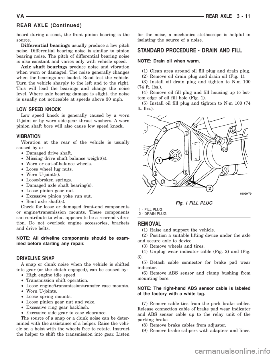
(2) Remove oil drain plug and drain oil (Fig. 1).
(3) Install oil drain plug and tighten to N´m 100
(74 ft. lbs.).
(4) Remove oil fill plug and fill housing up to bot-
tom edge of oil fill hole (Fig. 1).
(5) Install oil fill plug and tighten to N´m 100 (74
ft. lbs.).
REMOVAL
(1) Raise and support the vehicle.
(2) Position a suitable lifting device under the axle
and secure axle to device.
(3) Remove wheels and tires.
(4) Unplug wear indicator cable (Fig. 2) and (Fig.
3).
(5) Detach cable connector for brake pad wear
indicator.
(6) Remove ABS sensor and clamp bushing from
mounting bore.
NOTE: The right-hand ABS sensor cable is labeled
at the factory with a white tag.
(7) Remove cable ties from the park brake cables.
Release connection cable of brake pad wear indicator
and ABS sensor cable up to the relay unit of the
parking brake.
(8) Remove brake cables from adjuster.
(9) Remove brake calipers with adapters and lines.
Fig. 1 FILL PLUG
1 - FILL PLUG
2 - DRAIN PLUG
VAREAR AXLE 3 - 11
REAR AXLE (Continued)
Page 135 of 1232
lead dioxide (positive plate) or sponge lead (negative
plate). Insulators or plate separators made of a non-
conductive material are inserted between the positive
and negative plates to prevent them from contacting
or shorting against one another. These dissimilar
metal plates are submerged in a sulfuric acid and
water solution called an electrolyte.
The factory-installed low-maintenance bat-
tery has removable battery cell caps.Water can
be added to this battery. The chemical composition of
the metal coated plates within the low-maintenance
battery reduces battery gassing and water loss, at
normal charge and discharge rates. Therefore, the
battery should not require additional water in nor-
mal service. Rapid loss of electrolyte can be caused
by an overcharging condition. Be certain to diagnose
the charging system before returning the vehicle to
service.
OPERATION
The battery is designed to store electrical energy in
a chemical form. When an electrical load is applied to
the terminals of the battery, an electrochemical reac-
tion occurs. This reaction causes the battery to dis-
charge electrical current from its terminals. As the
battery discharges, a gradual chemical change takes
place within each cell. The sulfuric acid in the elec-
trolyte combines with the plate materials, causing
both plates to slowly change to lead sulfate. At the
same time, oxygen from the positive plate material
combines with hydrogen from the sulfuric acid, caus-
ing the electrolyte to become mainly water. The
chemical changes within the battery are caused by
the movement of excess or free electrons between the
positive and negative plate groups. This movement of
electrons produces a flow of electrical current
through the load device attached to the battery ter-
minals.
As the plate materials become more similar chem-
ically, and the electrolyte becomes less acid, the volt-
age potential of each cell is reduced. However, by
charging the battery with a voltage higher than that
of the battery itself, the battery discharging process
is reversed. Charging the battery gradually changes
the sulfated lead plates back into sponge lead and
lead dioxide, and the water back into sulfuric acid.
This action restores the difference in the electron
charges deposited on the plates, and the voltage
potential of the battery cells. For a battery to remain
useful, it must be able to produce high-amperage cur-
rent over an extended period. A battery must also be
able to accept a charge, so that its voltage potential
may be restored.
The battery is vented to release excess hydrogen
gas that is created when the battery is being charged
or discharged. However, even with these vents,hydrogen gas can collect in or around the battery. If
hydrogen gas is exposed to flame or sparks, it may
ignite. If the electrolyte level is low, the battery may
arc internally and explode. If the battery is equipped
with removable cell caps, add distilled water when-
ever the electrolyte level is below the top of the
plates. If the battery cell caps cannot be removed, the
battery must be replaced if the electrolyte level
becomes low.
DIAGNOSIS AND TESTING - BATTERY
The battery must be completely charged and the
terminals should be properly cleaned and inspected
before diagnostic procedures are performed. Refer to
Battery System Cleaning for the proper cleaning pro-
cedures, and Battery System Inspection for the
proper battery inspection procedures. Refer to Stan-
dard Procedures for the proper battery charging pro-
cedures.
MICRO 420 BATTERY TESTER
The Micro 420 automotive battery tester is
designed to help the dealership technicians diagnose
the cause of a defective battery. Follow the instruc-
tion manual supplied with the tester to properly
diagnose a vehicle. If the instruction manual is not
available refer to the standard procedure in this sec-
tion, which includes the directions for using the
Micro 420 battery tester.
WARNING: IF THE BATTERY SHOWS SIGNS OF
FREEZING, LEAKING OR LOOSE POSTS, DO NOT
TEST, ASSIST-BOOST, OR CHARGE. THE BATTERY
MAY ARC INTERNALLY AND EXPLODE. PERSONAL
INJURY AND/OR VEHICLE DAMAGE MAY RESULT.
WARNING: EXPLOSIVE HYDROGEN GAS FORMS IN
AND AROUND THE BATTERY. DO NOT SMOKE,
USE FLAME, OR CREATE SPARKS NEAR THE BAT-
TERY. PERSONAL INJURY AND/OR VEHICLE DAM-
AGE MAY RESULT.
WARNING: THE BATTERY CONTAINS SULFURIC
ACID, WHICH IS POISONOUS AND CAUSTIC. AVOID
CONTACT WITH THE SKIN, EYES, OR CLOTHING.
IN THE EVENT OF CONTACT, FLUSH WITH WATER
AND CALL A PHYSICIAN IMMEDIATELY. KEEP OUT
OF THE REACH OF CHILDREN.
A battery that will not accept a charge is faulty,
and must be replaced. Further testing is not
required. A fully-charged battery must be tested to
determine its cranking capacity. A battery that is ful-
ly-charged, but does not pass the Micro 420 or load
test, is faulty and must be replaced.
VABATTERY SYSTEM 8F - 7
BATTERY (Continued)
Page 136 of 1232
NOTE: Completely discharged batteries may take
several hours to accept a charge. Refer to Standard
Procedures for the proper battery charging proce-
dures.
STANDARD PROCEDURE
STANDARD PROCEDURE - BATTERY
CHARGING
Battery charging is the means by which the bat-
tery can be restored to its full voltage potential. A
battery is fully-charged when:
²Micro 420 electrical system tester indicates bat-
tery is OK.
²Three hydrometer tests, taken at one-hour inter-
vals, indicate no increase in the temperature-cor-
rected specific gravity of the battery electrolyte.
²Passes Load test.
²Open-circuit voltage of the battery is 12.65 volts
or above.
WARNING: IF THE BATTERY SHOWS SIGNS OF
FREEZING, LEAKING OR LOOSE POSTS, DO NOT
TEST, ASSIST-BOOST, OR CHARGE. THE BATTERY
MAY ARC INTERNALLY AND EXPLODE. PERSONAL
INJURY AND/OR VEHICLE DAMAGE MAY RESULT.
WARNING: EXPLOSIVE HYDROGEN GAS FORMS IN
AND AROUND THE BATTERY. DO NOT SMOKE,
USE FLAME, OR CREATE SPARKS NEAR THE BAT-
TERY. PERSONAL INJURY AND/OR VEHICLE DAM-
AGE MAY RESULT.
WARNING: THE BATTERY CONTAINS SULFURIC
ACID, WHICH IS POISONOUS AND CAUSTIC. AVOID
CONTACT WITH THE SKIN, EYES, OR CLOTHING.
IN THE EVENT OF CONTACT, FLUSH WITH WATER
AND CALL A PHYSICIAN IMMEDIATELY. KEEP OUT
OF THE REACH OF CHILDREN.
WARNING: IF THE BATTERY IS EQUIPPED WITH
REMOVABLE CELL CAPS, BE CERTAIN THAT EACH
OF THE CELL CAPS IS IN PLACE AND TIGHT
BEFORE THE BATTERY IS RETURNED TO SER-
VICE. PERSONAL INJURY AND/OR VEHICLE DAM-AGE MAY RESULT FROM LOOSE OR MISSING
CELL CAPS.
CAUTION: Always disconnect and isolate the bat-
tery negative cable before charging a battery. Do
not exceed sixteen volts while charging a battery.
Damage to the vehicle electrical system compo-
nents may result.
CAUTION: Battery electrolyte will bubble inside the
battery case during normal battery charging. Elec-
trolyte boiling or being discharged from the battery
vents indicates a battery overcharging condition.
Immediately reduce the charging rate or turn off the
charger to evaluate the battery condition. Damage
to the battery may result from overcharging.
CAUTION: The battery should not be hot to the
touch. If the battery feels hot to the touch, turn off
the charger and let the battery cool before continu-
ing the charging operation. Damage to the battery
may result.
Some battery chargers are equipped with polarity-
sensing circuitry. This circuitry protects the battery
charger and the battery from being damaged if they
are improperly connected. If the battery state-of-
charge is too low for the polarity-sensing circuitry to
detect, the battery charger will not operate. This
makes it appear that the battery will not accept
charging current. See the instructions provided by
the manufacturer of the battery charger for details
on how to bypass the polarity-sensing circuitry.
After the battery has been charged to 12.4 volts or
greater, retest the battery using the Micro 420 tester
or perform a load test to determine the battery
cranking capacity. If the battery will endure a load
test, return the battery to service. If the battery will
not endure a load test, it is faulty and must be
replaced.
Clean and inspect the battery hold downs, tray,
terminals, posts, and top before completing battery
service. Refer to Battery System Cleaning for the
proper battery system cleaning procedures, and Bat-
tery System Inspection for the proper battery system
inspection procedures.
8F - 8 BATTERY SYSTEMVA
BATTERY (Continued)
Page 835 of 1232
INSTALLATION - HIGH PRESSURE LINES
WARNING: HIGH-PRESSURE FUEL LINES DELIVER
DIESEL FUEL UNDER EXTREME PRESSURE FROM
THE INJECTION PUMP TO THE FUEL INJECTORS.
THIS MAY BE AS HIGH AS 1600BAR (23,200 PSI).
USE EXTREME CAUTION WHEN INSPECTING FOR
HIGH-PRESSURE FUEL LEAKS. FUEL UNDER THIS
AMOUNT OF PRESSURE CAN PENETRATE SKIN
CAUSING PERSONAL INJURY OR DEATH. INSPECT
FOR HIGH-PRESSURE LEAKS WITH A SHEET OF
CARD BOARD. WEAR SAFETY GOGGLES AND
ADEQUATE PROTECTIVE CLOTHING WHEN SER-
VICING FUEL SYSTEM.
WARNING: NO SPARKS, OPEN FLAMES OR SMOK-
ING. RISK OF POISONING FROM INHALING AND
SWALLOWING FUEL. RISK OF INJURY TO EYES
AND SKIN FROM CONTACT WITH FUEL. POUR
FUELS ONLY INTO SUITABLE AND APPROPRI-
ATELY MARKED CONTAINERS. WEAR PROTECTIVE
CLOTHING.
(1) Loosen the fuel rail mounting bolts to install
lines free of stress.
CAUTION: Inspect sealing cone at lines. Replace if
compression points exist. Ensure lines are exactly
located.
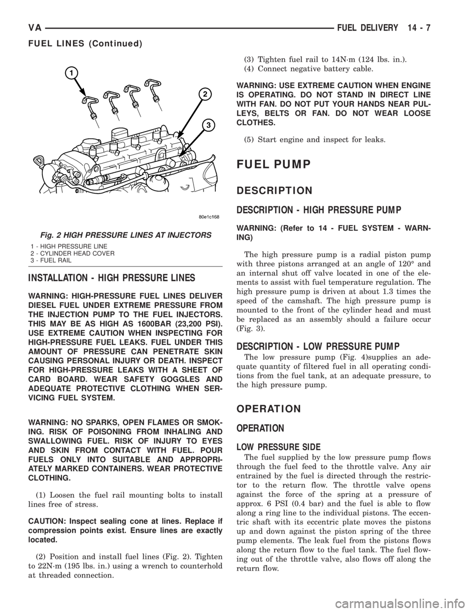
(2) Position and install fuel lines (Fig. 2). Tighten
to 22N´m (195 lbs. in.) using a wrench to counterhold
at threaded connection.(3) Tighten fuel rail to 14N´m (124 lbs. in.).
(4) Connect negative battery cable.
WARNING: USE EXTREME CAUTION WHEN ENGINE
IS OPERATING. DO NOT STAND IN DIRECT LINE
WITH FAN. DO NOT PUT YOUR HANDS NEAR PUL-
LEYS, BELTS OR FAN. DO NOT WEAR LOOSE
CLOTHES.
(5) Start engine and inspect for leaks.
FUEL PUMP
DESCRIPTION
DESCRIPTION - HIGH PRESSURE PUMP
WARNING: (Refer to 14 - FUEL SYSTEM - WARN-
ING)
The high pressure pump is a radial piston pump
with three pistons arranged at an angle of 120É and
an internal shut off valve located in one of the ele-
ments to assist with fuel temperature regulation. The
high pressure pump is driven at about 1.3 times the
speed of the camshaft. The high pressure pump is
mounted to the front of the cylinder head and must
be replaced as an assembly should a failure occur
(Fig. 3).
DESCRIPTION - LOW PRESSURE PUMP
The low pressure pump (Fig. 4)supplies an ade-
quate quantity of filtered fuel in all operating condi-
tions from the fuel tank, at an adequate pressure, to
the high pressure pump.
OPERATION
OPERATION
LOW PRESSURE SIDE
The fuel supplied by the low pressure pump flows
through the fuel feed to the throttle valve. Any air
entrained by the fuel is directed through the restric-
tor to the return flow. The throttle valve opens
against the force of the spring at a pressure of
approx. 6 PSI (0.4 bar) and the fuel is able to flow
along a ring line to the individual pistons. The eccen-
tric shaft with its eccentric plate moves the pistons
up and down against the piston spring of the three
pump elements. The leak fuel from the pistons flows
along the return flow to the fuel tank. The fuel flow-
ing out of the throttle valve, also flows off along the
return flow.
Fig. 2 HIGH PRESSURE LINES AT INJECTORS
1 - HIGH PRESSURE LINE
2 - CYLINDER HEAD COVER
3 - FUEL RAIL
VAFUEL DELIVERY 14 - 7
FUEL LINES (Continued)
Page 1040 of 1232
VISUAL INSPECTION BEFORE WATER LEAK TESTS
Verify that floor and body plugs are in place, body
drains are clear, and body components are properly
aligned and sealed. If component alignment or seal-
ing is necessary, refer to the appropriate section of
this group for proper procedures.
WATER LEAK TESTS
WARNING: DO NOT USE ELECTRIC SHOP LIGHTS
OR TOOLS IN WATER TEST AREA. PERSONAL
INJURY CAN RESULT.
When the conditions causing a water leak have
been determined, simulate the conditions as closely
as possible.
²If a leak occurs with the vehicle parked in a
steady light rain, flood the leak area with an open-
ended garden hose.
²If a leak occurs while driving at highway speeds
in a steady rain, test the leak area with a reasonable
velocity stream or fan spray of water. Direct the
spray in a direction comparable to actual conditions.
²If a leak occurs when the vehicle is parked on an
incline, hoist the end or side of the vehicle to simu-
late this condition. This method can be used when
the leak occurs when the vehicle accelerates, stops or
turns. If the leak occurs on acceleration, hoist the
front of the vehicle. If the leak occurs when braking,
hoist the back of the vehicle. If the leak occurs on left
turns, hoist the left side of the vehicle. If the leak
occurs on right turns, hoist the right side of the vehi-
cle. For hoisting recommendations (Refer to LUBRI-
CATION & MAINTENANCE/HOISTING -
STANDARD PROCEDURE).
WATER LEAK DETECTION
To detect a water leak point-of-entry, do a water
test and watch for water tracks or droplets forming
on the inside of the vehicle. If necessary, remove inte-
rior trim covers or panels to gain visual access to the
leak area. If the hose cannot be positioned without
being held, have someone help do the water test.
Some water leaks must be tested for a considerable
length of time to become apparent. When a leak
appears, find the highest point of the water track or
drop. The highest point usually will show the point of
entry. After leak point has been found, repair the
leak and water test to verify that the leak has
stopped.
Locating the entry point of water that is leaking
into a cavity between panels can be difficult. The
trapped water may splash or run from the cavity,
often at a distance from the entry point. Most water
leaks of this type become apparent after accelerating,
stopping, turning, or when on an incline.MIRROR INSPECTION METHOD
When a leak point area is visually obstructed, use
a suitable mirror to gain visual access. A mirror can
also be used to deflect light to a limited-access area
to assist in locating a leak point.
BRIGHT LIGHT LEAK TEST METHOD
Some water leaks in the luggage compartment can
be detected without water testing. Position the vehi-
cle in a brightly lit area. From inside the darkened
luggage compartment inspect around seals and body
seams. If necessary, have a helper direct a drop light
over the suspected leak areas around the luggage
compartment. If light is visible through a normally
sealed location, water could enter through the open-
ing.
PRESSURIZED LEAK TEST METHOD
When a water leak into the passenger compart-
ment cannot be detected by water testing, pressurize
the passenger compartment and soap test exterior of
the vehicle. To pressurize the passenger compart-
ment, close all doors and windows, start engine, and
set heater control to high blower in HEAT position. If
engine can not be started, connect a charger to the
battery to ensure adequate voltage to the blower.
With interior pressurized, apply dish detergent solu-
tion to suspected leak area on the exterior of the
vehicle. Apply detergent solution with spray device or
soft bristle brush. If soap bubbles occur at a body
seam, joint, seal or gasket, the leak entry point could
be at that location.
DIAGNOSIS AND TESTING - WIND NOISE
Wind noise is the result of most air leaks. Air leaks
can be caused by poor sealing, improper body compo-
nent alignment, body seam porosity, or missing plugs
in the engine compartment or door hinge pillar areas.
All body sealing points should be airtight in normal
driving conditions. Moving sealing surfaces will not
always seal airtight under all conditions. At times,
side glass or door seals will allow wind noise to be
noticed in the passenger compartment during high
cross winds. Over compensating on door or glass
adjustments to stop wind noise that occurs under
severe conditions can cause premature seal wear and
excessive closing or latching effort. After a repair pro-
cedure has been performed, test vehicle to verify
noise has stopped before returning vehicle to use.
VISUAL INSPECTION BEFORE TESTS
Verify that floor and body plugs are in place and
body components are aligned and sealed. If compo-
nent alignment or sealing is necessary, refer to the
appropriate section of this group for proper proce-
dures.
23 - 2 BODYVA
BODY (Continued)
Page 1217 of 1232
FREEWHEELING CLUTCH -
DISASSEMBLY......................21-106
FREEWHEELING CLUTCH - OPERATION . . 21-105
FROM FUEL FILTER - STANDARD
PROCEDURES, DRAINING WATER........14-2
FROM GEAR TO COOLER TUBE -
INSTALLATION, RETURN HOSE..........19-15
FROM GEAR TO COOLER TUBE -
REMOVAL, RETURN HOSE.............19-15
FROM PUMP TO COOLER TUBE -
INSTALLATION, RETURN LINE..........19-15
FROM PUMP TO COOLER TUBE -
REMOVAL, RETURN LINE..............19-15
FRONT - INSTALLATION............5-14,5-24
FRONT - INSTALLATION, CRANKSHAFT
OIL SEAL............................9-38
FRONT - INSTALLATION, SEAT..........23-77
FRONT - INSTALLATION, SEAT
ADJUSTERS.........................23-78
FRONT - INSTALLATION, SEAT BACK.....23-77
FRONT - INSTALLATION, SEAT CUSHION . . 23-78
FRONT - REMOVAL................5-13,5-24
FRONT - REMOVAL, CRANKSHAFT OIL
SEAL...............................9-38
FRONT - REMOVAL, SEAT..............23-77
FRONT - REMOVAL, SEAT ADJUSTERS . . . 23-78
FRONT - REMOVAL, SEAT BACK.........23-77
FRONT - REMOVAL, SEAT CUSHION......23-78
FRONT BUMPER - STEPS -
INSTALLATION........................13-2
FRONT BUMPER - STEPS - REMOVAL.....13-2
FRONT COVER - INSTALLATION,
CYLINDER HEAD......................9-26
FRONT COVER - REMOVAL, CYLINDER
HEAD...............................9-23
FRONT DOOR INNER BELT
WEATHERSTRIP - INSTALLATION........23-87
FRONT DOOR INNER BELT
WEATHERSTRIP - REMOVAL............23-87
FRONT DOOR OUTER BELT
WEATHERSTRIP - INSTALLATION........23-87
FRONT DOOR OUTER BELT
WEATHERSTRIP - REMOVAL............23-87
FRONT (DRW) - INSTALLATION . . 5-11,5-13,5-21
FRONT (DRW) - REMOVAL.......5-12,5-20,5-9
FRONT FASCIA - INSTALLATION..........13-2
FRONT FASCIA - REMOVAL..............13-2
FRONT LAMP UNIT - ADJUSTMENT......8L-12
FRONT LAMP UNIT - INSTALLATION.....8L-12
FRONT LAMP UNIT - REMOVAL.........8L-12
FRONT POSITION LAMP BULB -
INSTALLATION.......................8L-14
FRONT POSITION LAMP BULB -
REMOVAL..........................8L-14
FRONT SEAT BELT & RETRACTOR -
INSTALLATION......................8O-21
FRONT SEAT BELT & RETRACTOR -
REMOVAL..........................8O-19
FRONT SEAT BELT BUCKLE -
INSTALLATION......................8O-23
FRONT SEAT BELT BUCKLE - REMOVAL . . 8O-22
FRONT (SRW) - INSTALLATION . . 5-10,5-12,5-21
FRONT (SRW) - REMOVAL.......5-11,5-19,5-9
FRONT SUSPENSION, SPECIAL TOOLS....19-11
FRONT SUSPENSION, SPECIAL TOOLS.....2-2
FRONT TURN/PARK/SIDE MARKER LAMP
BULB - INSTALLATION................8L-15
FRONT TURN/PARK/SIDE MARKER LAMP
BULB - REMOVAL....................8L-14
FRONT WHEEL SPEED SENSOR -
INSTALLATION........................5-30
FRONT WHEEL SPEED SENSOR -
REMOVAL...........................5-30
FUEL DOSING PUMP - DESCRIPTION.....24-74
FUEL DOSING PUMP - INSTALLATION....24-74
FUEL DOSING PUMP - OPERATION......24-74
FUEL DOSING PUMP - REMOVAL........24-74
FUEL FILL DOOR - INSTALLATION.......23-47
FUEL FILL DOOR - REMOVAL...........23-47
FUEL FILTER - DESCRIPTION............14-5
FUEL FILTER - INSTALLATION
............14-6
FUEL FILTER - OPERATION
..............14-5
FUEL FILTER - REMOVAL
...............14-5
FUEL FILTER - STANDARD
PROCEDURES, DRAINING WATER
FROM
..............................14-2
FUEL FILTER CLOGGED INDICATOR -
DESCRIPTION
.......................8J-15FUEL FILTER CLOGGED INDICATOR -
OPERATION.........................8J-15
FUEL GAUGE - DESCRIPTION...........8J-16
FUEL GAUGE - OPERATION.............8J-16
FUEL INDICATOR - DESCRIPTION, LOW . . . 8J-18
FUEL INDICATOR - OPERATION, LOW.....8J-18
FUEL INJECTOR, DESCRIPTION.........14-20
FUEL INJECTORS - STANDARD
PROCEDURE, CLEANING...............14-22
FUEL LEVEL SENDING UNIT / SENSOR -
DESCRIPTION.......................14-15
FUEL LEVEL SENDING UNIT / SENSOR -
INSTALLATION.......................14-15
FUEL LEVEL SENDING UNIT / SENSOR -
REMOVAL..........................14-15
FUEL LINE - INSTALLATION............24-76
FUEL LINE - REMOVAL................24-75
FUEL LINES - DIAGNOSIS AND TESTING,
HIGH PRESSURE......................14-1
FUEL LINES - STANDARD PROCEDURE,
DISCONNECTING AND CONNECTING......14-2
FUEL PRESSURE SOLENOID -
DESCRIPTION.......................14-27
FUEL PRESSURE SOLENOID -
INSTALLATION.......................14-28
FUEL PRESSURE SOLENOID -
OPERATION.........................14-27
FUEL PRESSURE SOLENOID - REMOVAL . . 14-28
FUEL PUMP TEST - STANDARD
PROCEDURE, LOW PRESSURE...........14-3
FUEL RAIL - DESCRIPTION..............14-11
FUEL RAIL - INSTALLATION............14-11
FUEL RAIL - OPERATION...............14-11
FUEL RAIL - REMOVAL................14-11
FUEL REQUIREMENTS - DIESEL ENGINE
- DESCRIPTION........................0-1
FUEL SENSOR - DESCRIPTION, WATER
IN ................................14-16
FUEL SENSOR - OPERATION, WATER IN . . 14-16
FUEL SHUTOFF SOL - DESCRIPTION, HI
PRESSURE.........................14-16
FUEL SHUTOFF SOL - OPERATION, HI
PRESSURE.........................14-16
FUEL SUPPLY RESTRICTIONS -
DIAGNOSIS AND TESTING..............14-5
FUEL SYSTEM - DIAGNOSIS AND
TESTING, AIR IN......................14-2
FUEL SYSTEM COMPONENTS -
STANDARD PROCEDURES, CLEANING.....14-2
FUEL SYSTEM PRESSURE - WARNING,
HIGH...............................14-1
FUEL SYSTEM, SPECIAL TOOLS..........14-5
FUEL TANK - DESCRIPTION............14-12
FUEL TANK - INSTALLATION............14-13
FUEL TANK - REMOVAL...............14-12
FUEL TANK MODULE - DESCRIPTION.....14-13
FUEL TANK MODULE - INSTALLATION....14-14
FUEL TANK MODULE - REMOVAL........14-13
FUEL TEMPERATURE SENSOR -
DESCRIPTION.......................14-29
FUEL TEMPERATURE SENSOR -
INSTALLATION.......................14-29
FUEL TEMPERATURE SENSOR -
OPERATION.........................14-29
FUEL TEMPERATURE SENSOR -
REMOVAL..........................14-29
FUNCTION TEST - DIAGNOSIS AND
TESTING............................24-3
FUSE BLOCK #1 - DESCRIPTION......8W-97-2
FUSE BLOCK #1 - INSTALLATION......8W-97-3
FUSE BLOCK #1 - OPERATION........8W-97-2
FUSE BLOCK #1 - REMOVAL.........8W-97-3
FUSE BLOCK #2 - DESCRIPTION......8W-97-3
FUSE BLOCK #2 - OPERATION........8W-97-3
FUSES POWERING SEVERAL LOADS -
STANDARD PROCEDURE, TESTING
FOR A SHORT TO GROUND ON.......8W-01-8
GALLERY PLUGS - STANDARD
PROCEDURE, REPLACING ENGINE
CORE AND OIL.......................9-34
GAP - STANDARD PROCEDURE,
COMPRESSOR CLUTCH AIR
.............24-9
GAP AND FLUSH - SPECIFICATIONS
......23-88
GAUGE - DESCRIPTION, ENGINE
TEMPERATURE
......................8J-15
GAUGE - DESCRIPTION, FUEL
...........8J-16
GAUGE - OPERATION, ENGINE
TEMPERATURE
......................8J-15GAUGE - OPERATION, FUEL............8J-16
GAUGES - DIAGNOSIS AND TESTING,
PRESSURE..........................22-8
GEAR - DESCRIPTION..................19-8
GEAR - INSTALLATION.................19-8
GEAR - INSTALLATION, INTERMEDIATE....9-66
GEAR - REMOVAL.....................19-8
GEAR - REMOVAL, INTERMEDIATE........9-61
GEAR SELECTOR INDICATOR -
DESCRIPTION.......................8J-17
GEAR SELECTOR INDICATOR -
OPERATION.........................8J-17
GEAR TO COOLER TUBE -
INSTALLATION, RETURN HOSE FROM....19-15
GEAR TO COOLER TUBE - REMOVAL,
RETURN HOSE FROM.................19-15
GEARSHIFT CABLE - DIAGNOSIS AND
TESTING..........................21-109
GEARSHIFT CABLE - INSTALLATION.....21-109
GEARSHIFT CABLE - REMOVAL........21-109
GEARTRAIN - ASSEMBLY, PLANETARY . . . 21-131
GEARTRAIN - DESCRIPTION,
PLANETARY........................21-130
GEARTRAIN - DISASSEMBLY,
PLANETARY........................21-131
GEARTRAIN - OPERATION, PLANETARY . . 21-130
GENERAL - WARNINGS.............8W-01-6
GENERATOR - DESCRIPTION...........8F-18
GENERATOR - INSTALLATION...........8F-18
GENERATOR - OPERATION.............8F-18
GENERATOR - REMOVAL...............8F-18
GENERATOR DECOUPLER - DIAGNOSIS
AND TESTING.......................8F-19
GENERATOR DECOUPLER PULLEY -
DESCRIPTION.......................8F-19
GENERATOR DECOUPLER PULLEY -
INSTALLATION.......................8F-21
GENERATOR DECOUPLER PULLEY -
OPERATION.........................8F-19
GENERATOR DECOUPLER PULLEY -
REMOVAL..........................8F-20
GLASS - INSTALLATION, DOOR....23-15,23-31,
23-46
GLASS - INSTALLATION, SIDE VIEW
MIRROR...........................23-49
GLASS - REMOVAL, DOOR . . . 23-15,23-31,23-46
GLASS - REMOVAL, SIDE VIEW MIRROR . . 23-49
GLOVE BOX - INSTALLATION...........23-56
GLOVE BOX - REMOVAL...............23-56
GLOW PLUG - INSTALLATION............8I-1
GLOW PLUG - REMOVAL................8I-1
GLOW PLUG RELAY - DESCRIPTION.......8I-2
GLOW PLUG RELAY - OPERATION........8I-2
GLOW PLUG RELAYS - DIAGNOSIS AND
TESTING.............................8I-2
GRILLE - INSTALLATION...............23-47
GRILLE - REMOVAL..................23-47
GROUND - STANDARD PROCEDURE,
TESTING FOR A SHORT TO..........8W-01-8
GROUND AND SPLICE INFORMATION -
DESCRIPTION, CONNECTOR..........8W-01-5
GROUND ON FUSES POWERING
SEVERAL LOADS - STANDARD
PROCEDURE, TESTING FOR A SHORT
TO
..............................8W-01-8
GUIDE RAIL - INSTALLATION, CYLINDER
HEAD
...............................9-26
GUIDE RAIL - REMOVAL, CYLINDER
HEAD
...............................9-24
HANDLE - INSTALLATION, ASSIST
.......23-68
HANDLE - INSTALLATION, EXTERIOR
....23-16,
23-33,23-36
HANDLE - INSTALLATION, LATCH
RELEASE
...........................23-52
HANDLE - REMOVAL, ASSIST
...........23-68
HANDLE - REMOVAL, EXTERIOR
. . . 23-16,23-32,
23-36
HANDLE - REMOVAL, LATCH RELEASE
. . . 23-52
HANDLE ACTUATOR - INSTALLATION,
INSIDE
........................23-34,23-37
HANDLE ACTUATOR - REMOVAL, INSIDE
. 23-34,
23-37
HANDLING NON-DEPLOYED
SUPPLEMENTAL RESTRAINTS -
STANDARD PROCEDURE
...............8O-6
HARNESS - DIAGNOSIS AND TESTING,
WIRING
..........................8W-01-6
VAINDEX 7
Description Group-Page Description Group-Page Description Group-Page