2005 MERCEDES-BENZ SPRINTER coolant capacity
[x] Cancel search: coolant capacityPage 14 of 1232
Full synthetic oils, such as Mobilt1 0W-40, is
required if the ASSYST Oil Service Reminder is fol-
lowed. Use of a lower quality oil on this service
schedule may cause severe engine damage.
DESCRIPTION - AUTOMATIC TRANSMISSION
FLUID - NAG1
NOTE: Refer to Service Procedures in this group for
fluid level checking procedures.
Shellt3403 Automatic Transmission Fluid is the
recommended fluid for the NAG1 DaimlerChrysler
automatic transmission.
Dexron II fluid IS NOT recommended. Clutch
chatter can result from the use of improper
fluid.
MopartATF+4, Automatic Transmission Fluid, or
other fluids meeting MS-9602, may be used if Shellt
3403 Automatic Transmission Fluid is not available.
Shellt3403 Automatic Transmission Fluid when
new is red in color. The ATF is dyed red so it can be
identified from other fluids used in the vehicle such
as engine oil or antifreeze. The red color is not per-
manent and is not an indicator of fluid condition. As
the vehicle is driven, the ATF will begin to look
darker in color and may eventually become brown.
This is normal.
FLUID ADDITIVES
DaimlerChrysler strongly recommends against the
addition of any fluids to the transmission, other than
those automatic transmission fluids listed above.
Exceptions to this policy are the use of special dyes
to aid in detecting fluid leaks.
Various ªspecialº additives and supplements exist
that claim to improve shift feel and/or quality. These
additives and others also claim to improve converter
clutch operation and inhibit overheating, oxidation,
varnish, and sludge. These claims have not been sup-
ported to the satisfaction of DaimlerChrysler and
these additivesmust not be used.The use of trans-
mission ªsealersº should also be avoided, since they
may adversely affect the integrity of transmission
seals.
OPERATION - AUTOMATIC TRANSMISSION
FLUID
The automatic transmission fluid is selected based
upon several qualities. The fluid must provide a high
level of protection for the internal components by
providing a lubricating film between adjacent metal
components. The fluid must also be thermally stable
so that it can maintain a consistent viscosity through
a large temperature range. If the viscosity stays con-
stant through the temperature range of operation,transmission operation and shift feel will remain con-
sistent. Transmission fluid must also be a good con-
ductor of heat. The fluid must absorb heat from the
internal transmission components and transfer that
heat to the transmission case.
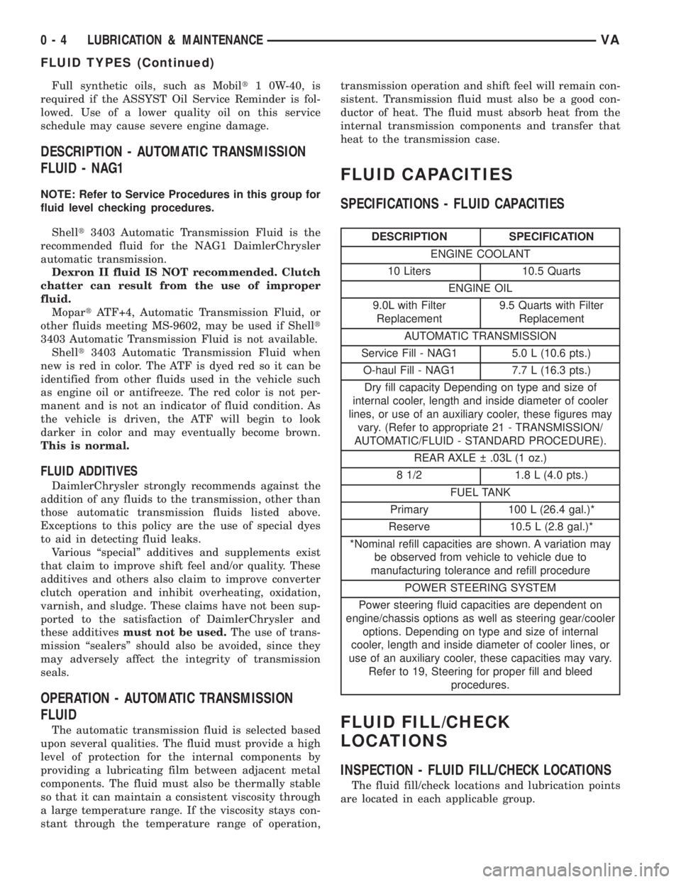
FLUID CAPACITIES
SPECIFICATIONS - FLUID CAPACITIES
DESCRIPTION SPECIFICATION
ENGINE COOLANT
10 Liters 10.5 Quarts
ENGINE OIL
9.0L with Filter
Replacement9.5 Quarts with Filter
Replacement
AUTOMATIC TRANSMISSION
Service Fill - NAG1 5.0 L (10.6 pts.)
O-haul Fill - NAG1 7.7 L (16.3 pts.)
Dry fill capacity Depending on type and size of
internal cooler, length and inside diameter of cooler
lines, or use of an auxiliary cooler, these figures may
vary. (Refer to appropriate 21 - TRANSMISSION/
AUTOMATIC/FLUID - STANDARD PROCEDURE).
REAR AXLE .03L (1 oz.)
8 1/2 1.8 L (4.0 pts.)
FUEL TANK
Primary 100 L (26.4 gal.)*
Reserve 10.5 L (2.8 gal.)*
*Nominal refill capacities are shown. A variation may
be observed from vehicle to vehicle due to
manufacturing tolerance and refill procedure
POWER STEERING SYSTEM
Power steering fluid capacities are dependent on
engine/chassis options as well as steering gear/cooler
options. Depending on type and size of internal
cooler, length and inside diameter of cooler lines, or
use of an auxiliary cooler, these capacities may vary.
Refer to 19, Steering for proper fill and bleed
procedures.
FLUID FILL/CHECK
LOCATIONS
INSPECTION - FLUID FILL/CHECK LOCATIONS
The fluid fill/check locations and lubrication points
are located in each applicable group.
0 - 4 LUBRICATION & MAINTENANCEVA
FLUID TYPES (Continued)
Page 114 of 1232
(16) Install A/C condenser.
(17) Install front bumper.
(18) Install front end cross member.
(19) Refill power steering to proper level.
(20) Refill transmission to proper level.
(21) Close radiator drain plug and refill the cooling
system to the correct level with the appropriate cool-
ant mixture.
(22) Recharge air conditioning.
(23) Run engine until warm and check for leaks.
RADIATOR PRESSURE CAP
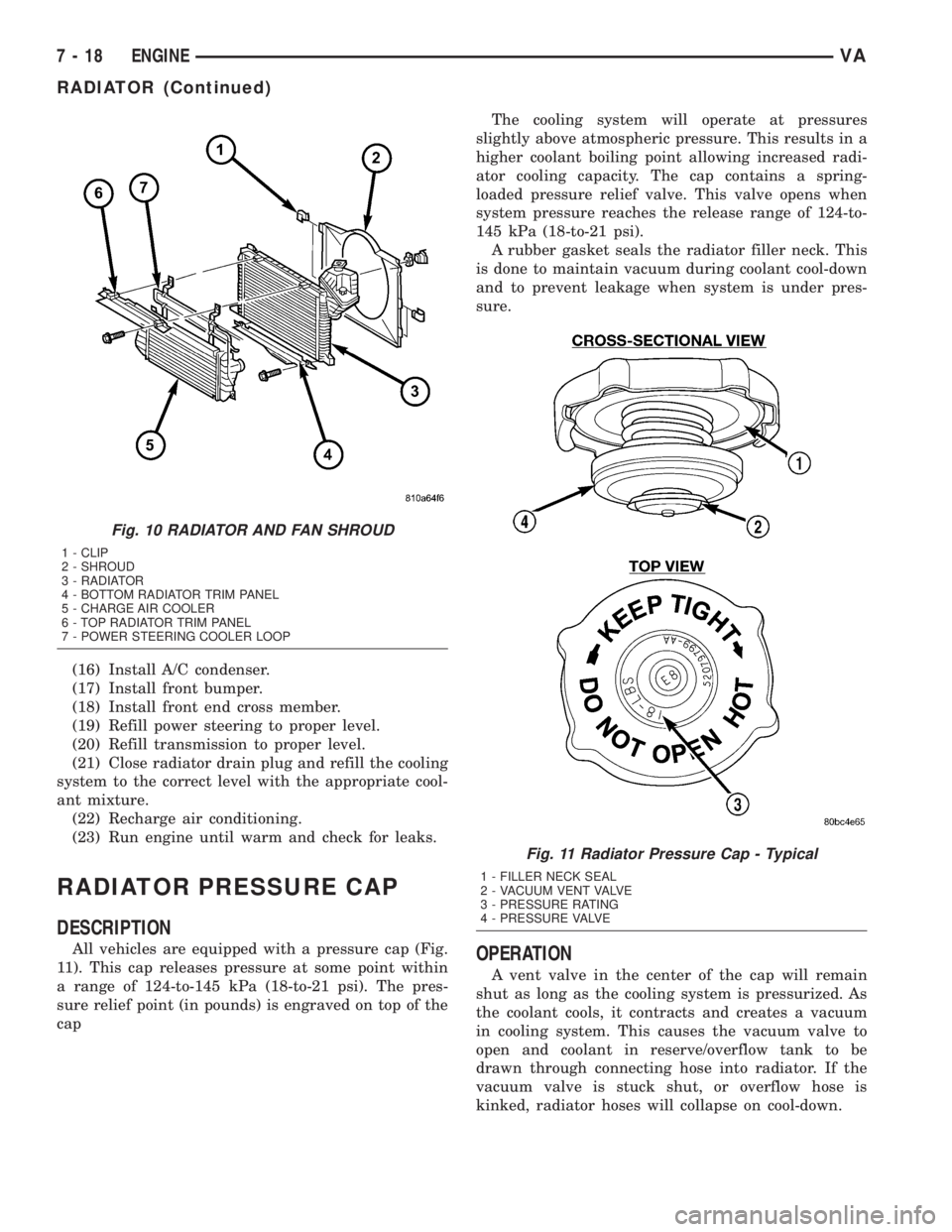
DESCRIPTION
All vehicles are equipped with a pressure cap (Fig.
11). This cap releases pressure at some point within
a range of 124-to-145 kPa (18-to-21 psi). The pres-
sure relief point (in pounds) is engraved on top of the
capThe cooling system will operate at pressures
slightly above atmospheric pressure. This results in a
higher coolant boiling point allowing increased radi-
ator cooling capacity. The cap contains a spring-
loaded pressure relief valve. This valve opens when
system pressure reaches the release range of 124-to-
145 kPa (18-to-21 psi).
A rubber gasket seals the radiator filler neck. This
is done to maintain vacuum during coolant cool-down
and to prevent leakage when system is under pres-
sure.OPERATION
A vent valve in the center of the cap will remain
shut as long as the cooling system is pressurized. As
the coolant cools, it contracts and creates a vacuum
in cooling system. This causes the vacuum valve to
open and coolant in reserve/overflow tank to be
drawn through connecting hose into radiator. If the
vacuum valve is stuck shut, or overflow hose is
kinked, radiator hoses will collapse on cool-down.
Fig. 10 RADIATOR AND FAN SHROUD
1 - CLIP
2 - SHROUD
3 - RADIATOR
4 - BOTTOM RADIATOR TRIM PANEL
5 - CHARGE AIR COOLER
6 - TOP RADIATOR TRIM PANEL
7 - POWER STEERING COOLER LOOP
Fig. 11 Radiator Pressure Cap - Typical
1 - FILLER NECK SEAL
2 - VACUUM VENT VALVE
3 - PRESSURE RATING
4 - PRESSURE VALVE
7 - 18 ENGINEVA
RADIATOR (Continued)
Page 1131 of 1232
To maintain minimum evaporator temperature and
prevent evaporator freezing, an evaporator tempera-
ture sensor is used.
Vehicles equipped with the available rear A/C sys-
tem have an individual temperature control and
blower motor speed switches. When the rear A/C sys-
tem is turned on, a solenoid valve opens the rear
refrigerant circuit and activates the blower motor for
the rear evaporator. The circulated internal air tem-
perature is measured by a temperature sensor and
the temperature value is compared within the rear
A/C control module to an adjusted value at the tem-
perature control switch. To prevent icing of the rear
evaporator, the temperature switch cuts off the flow
of refrigerant through the rear A/C circuit by de-en-
ergizing the solenoid valve.
The front and rear A/C systems are designed for
the use of non-CFC, R-134a refrigerant only. Both
the front and rear systems use an expansion valve to
meter refrigerant flow to the evaporator.
DIAGNOSIS AND TESTING
DIAGNOSIS AND TESTING - FUNCTION TEST
The ATC system can perform an self-test, which
can be activated by the DRBIIItscan tool to confirm
that the air conditioning system is performing satis-
factorily. This test provides a quick confirmation of
heater - air conditioning system performance to the
service technician. Refer to Body Diagnostic Proce-
dures for the appropriate diagnostic information.
DIAGNOSIS AND TESTING - A/C
PERFORMANCE TEST
The air conditioning system is designed to provide
the passenger compartment with low temperature
and low specific humidity air. The evaporator, located
in the heater housing on the dash panel below the
instrument panel, is cooled to temperatures near the
freezing point. As warm damp air passes through the
cooled evaporator, the air transfers its heat to the
refrigerant in the evaporator and the moisture in the
air condenses on the evaporator fins. During periods
of high heat and humidity, an air conditioning sys-
tem will be more effective in the Recirculation Mode.
With the system in the Recirculation Mode, only air
from the passenger compartment passes through the
evaporator. As the passenger compartment air dehu-
midifies, the air conditioning system performance
levels improve.
Humidity has an important bearing on the temper-
ature of the air delivered to the interior of the vehi-
cle. It is important to understand the effect that
humidity has on the performance of the air condition-
ing system. When humidity is high, the evaporatorhas to perform a double duty. It must lower the air
temperature, and it must lower the temperature of
the moisture in the air that condenses on the evapo-
rator fins. Condensing the moisture in the air trans-
fers heat energy into the evaporator fins and tubing.
This reduces the amount of heat the evaporator can
absorb from the air. High humidity greatly reduces
the ability of the evaporator to lower the temperature
of the air.
However, evaporator capacity used to reduce the
amount of moisture in the air is not wasted. Remov-
ing some of the moisture out of the air entering the
vehicle adds to the comfort of the passengers.
Although, an owner may expect too much from their
air conditioning system on humid days. A perfor-
mance test is the best way to determine whether the
system is performing up to standard. This test also
provides valuable clues as to the possible cause of
trouble with the air conditioning system.
WARNING: REFER TO THE APPLICABLE WARN-
INGS AND CAUTIONS FOR THIS SYSTEM BEFORE
PERFORMING THE FOLLOWING OPERATION (Refer
to 24 - HEATING & AIR CONDITIONING/PLUMBING -
WARNING) and (Refer to 24 - HEATING & AIR CON-
DITIONING/PLUMBING - CAUTION).
NOTE: Very specific instructions and conditions
pertain to this procedure which are significantly dif-
ferent than procedures used in other vehicle appli-
cations. Follow each step in the order they are
presented. Do not skip steps or change conditions
from those stated or results will be adversely
affected and invalid.
The compressor clutch is de-energized under any of
the following conditions:
²Blocked compressor (thermal fuse in the pulley)
²Low pressure in the system
²Low evaporator temperature
²Hard acceleration (WOT)
²High coolant temperatures
(1) Place the vehicle in the shade with all widows
open.
(2) Turn the temperature control to cold.
(3) Select Fresh Air, not Recirculate and open all
air conditioning duct louvers.
(4) Start the vehicle and allow it to idle.
(5) Turn the blower switch to the maximum blower
speed setting and allow to operate for a short period
of time before proceeding.
(6) Perform an outlet temperature test as follows:
a. Turn the blower switch to the lowest blower
speed setting.
b. Insert a thermometer into a center duct for at
least five minutes.
VAHEATING & AIR CONDITIONING 24 - 3
HEATING & AIR CONDITIONING (Continued)
Page 1133 of 1232
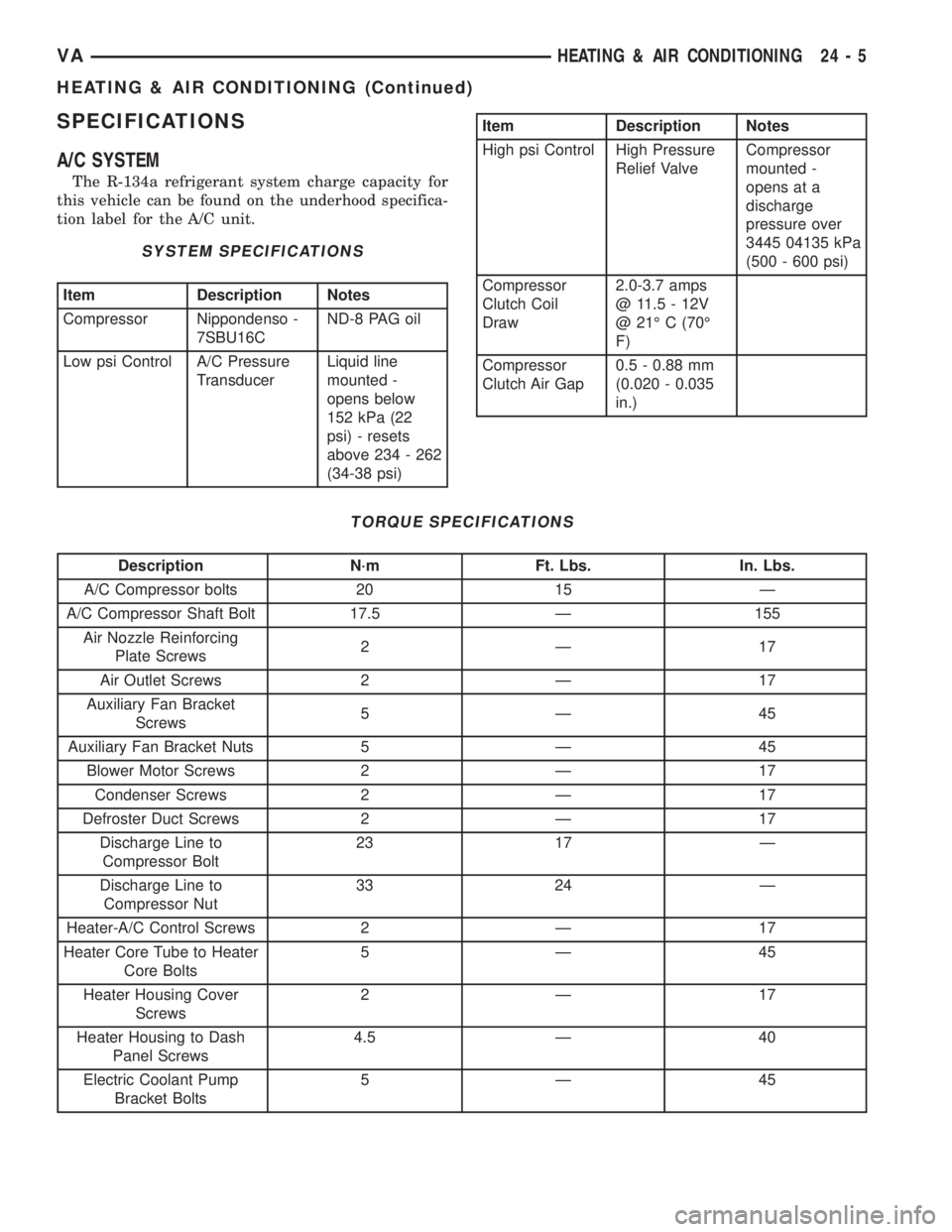
SPECIFICATIONS
A/C SYSTEM
The R-134a refrigerant system charge capacity for
this vehicle can be found on the underhood specifica-
tion label for the A/C unit.
SYSTEM SPECIFICATIONS
Item Description Notes
Compressor Nippondenso -
7SBU16CND-8 PAG oil
Low psi Control A/C Pressure
TransducerLiquid line
mounted -
opens below
152 kPa (22
psi) - resets
above 234 - 262
(34-38 psi)
Item Description Notes
High psi Control High Pressure
Relief ValveCompressor
mounted -
opens at a
discharge
pressure over
3445 04135 kPa
(500 - 600 psi)
Compressor
Clutch Coil
Draw2.0-3.7 amps
@ 11.5 - 12V
@ 21É C (70É
F)
Compressor
Clutch Air Gap0.5 - 0.88 mm
(0.020 - 0.035
in.)
TORQUE SPECIFICATIONS
Description N´m Ft. Lbs. In. Lbs.
A/C Compressor bolts 20 15 Ð
A/C Compressor Shaft Bolt 17.5 Ð 155
Air Nozzle Reinforcing
Plate Screws2Ð 17
Air Outlet Screws 2 Ð 17
Auxiliary Fan Bracket
Screws5Ð 45
Auxiliary Fan Bracket Nuts 5 Ð 45
Blower Motor Screws 2 Ð 17
Condenser Screws 2 Ð 17
Defroster Duct Screws 2 Ð 17
Discharge Line to
Compressor Bolt23 17 Ð
Discharge Line to
Compressor Nut33 24 Ð
Heater-A/C Control Screws 2 Ð 17
Heater Core Tube to Heater
Core Bolts5Ð 45
Heater Housing Cover
Screws2Ð 17
Heater Housing to Dash
Panel Screws4.5 Ð 40
Electric Coolant Pump
Bracket Bolts5Ð 45
VAHEATING & AIR CONDITIONING 24 - 5
HEATING & AIR CONDITIONING (Continued)
Page 1171 of 1232
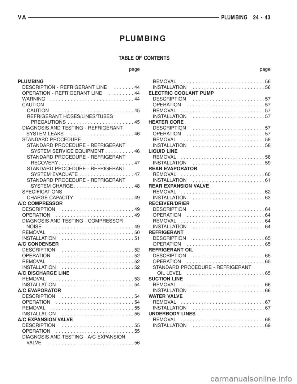
PLUMBING
TABLE OF CONTENTS
page page
PLUMBING
DESCRIPTION - REFRIGERANT LINE.......44
OPERATION - REFRIGERANT LINE.........44
WARNING.............................44
CAUTION
CAUTION...........................45
REFRIGERANT HOSES/LINES/TUBES
PRECAUTIONS.......................45
DIAGNOSIS AND TESTING - REFRIGERANT
SYSTEM LEAKS......................46
STANDARD PROCEDURE
STANDARD PROCEDURE - REFRIGERANT
SYSTEM SERVICE EQUIPMENT..........46
STANDARD PROCEDURE - REFRIGERANT
RECOVERY..........................47
STANDARD PROCEDURE - REFRIGERANT
SYSTEM EVACUATE...................47
STANDARD PROCEDURE - REFRIGERANT
SYSTEM CHARGE.....................48
SPECIFICATIONS
CHARGE CAPACITY...................49
A/C COMPRESSOR
DESCRIPTION.........................49
OPERATION...........................49
DIAGNOSIS AND TESTING - COMPRESSOR
NOISE..............................49
REMOVAL.............................50
INSTALLATION.........................51
A/C CONDENSER
DESCRIPTION.........................52
OPERATION...........................52
REMOVAL.............................52
INSTALLATION.........................52
A/C DISCHARGE LINE
REMOVAL.............................53
INSTALLATION.........................54
A/C EVAPORATOR
DESCRIPTION.........................54
OPERATION...........................54
REMOVAL.............................55
INSTALLATION.........................55
A/C EXPANSION VALVE
DESCRIPTION.........................55
OPERATION...........................55
DIAGNOSIS AND TESTING - A/C EXPANSION
VALVE ..............................56REMOVAL.............................56
INSTALLATION.........................56
ELECTRIC COOLANT PUMP
DESCRIPTION.........................57
OPERATION...........................57
REMOVAL.............................57
INSTALLATION.........................57
HEATER CORE
DESCRIPTION.........................57
OPERATION...........................57
REMOVAL.............................58
INSTALLATION.........................58
LIQUID LINE
REMOVAL.............................58
INSTALLATION.........................59
REAR EVAPORATOR
REMOVAL.............................60
INSTALLATION.........................61
REAR EXPANSION VALVE
REMOVAL.............................62
INSTALLATION.........................63
RECEIVER/DRIER
DESCRIPTION.........................64
OPERATION...........................64
REMOVAL.............................64
INSTALLATION.........................64
REFRIGERANT
DESCRIPTION.........................65
OPERATION...........................65
REFRIGERANT OIL
DESCRIPTION.........................65
OPERATION...........................65
STANDARD PROCEDURE - REFRIGERANT
OIL LEVEL...........................65
SUCTION LINE
REMOVAL.............................66
INSTALLATION.........................66
WAT E R VA LV E
REMOVAL.............................67
INSTALLATION.........................67
UNDERBODY LINES
REMOVAL.............................68
INSTALLATION.........................69
VAPLUMBING 24 - 43