2005 MERCEDES-BENZ SPRINTER ad blue
[x] Cancel search: ad bluePage 187 of 1232
nosed using conventional diagnostic tools and meth-
ods. For proper diagnosis of the instrument cluster
circuitry that controls the fuel gauge, a DRBIIItscan
tool is required. Refer to the appropriate diagnostic
information.
GEAR SELECTOR INDICATOR
DESCRIPTION
An electronic automatic transmission gear selector
indicator is standard equipment on all instrument
clusters. The gear selector indicator information is
displayed in the center of the multi-function indicator
Liquid Crystal Display (LCD) located near the lower
edge of the instrument cluster, directly below the
speedometer. The gear selector indicator displays the
following characters as they are selected: ªP,º ªR,º
ªN,º ªD,º ª4,º ª3,º ª2,º and ª1.º Respectively, these
characters represent the currently selected park,
reverse, neutral, drive, fourth gear, third gear, second
gear, and first gear positions of the transmission gear
selector lever on the instrument panel.
The indications of the gear selector indicator are
not visible unless the multi-function indicator LCD is
illuminated and the engine is running. When illumi-
nated, each indication appears as a dark character
silhouetted against an amber field. When the exterior
lighting is turned Off, the display is illuminated at
maximum brightness. When the exterior lighting is
turned On, the display illumination level can be
adjusted in concert with the cluster general illumina-
tion lighting using the ª+º (plus) and ª2º (minus)
multi-function indicator push buttons. The gear
selector indicator is serviced as a unit with the
instrument cluster.
OPERATION
The electronic gear selector indicator gives an indi-
cation to the vehicle operator of the transmission
gear that is currently selected with the automatic
transmission gear selector lever. This indicator is
controlled by the instrument cluster circuit board
based upon cluster programming and electronic mes-
sages received from the Transmission Control Module
(TCM) over the Controller Area Network (CAN) data
bus. The gear selector indicator information is dis-
played by the multi-function indicator Liquid Crystal
Display (LCD) unit on the instrument cluster elec-
tronic circuit board. The multi-function indicator
LCD is completely controlled by the instrument clus-
ter logic circuit, and that logic will only allow the
gear selector indicator information to be displayed
when the instrument cluster detects that the ignition
switch is in the On position. Therefore, the gearselector indicator will always be off when the ignition
switch is in any position except On.
The TCM continually monitors the transmission
range sensor, then sends the proper gear selector
indicator position messages to the instrument cluster.
For proper diagnosis of the transmission range sen-
sor, the TCM, the CAN data bus, or the electronic
message inputs to the instrument cluster that control
the gear selector indicator, a DRBIIItscan tool is
required. Refer to the appropriate diagnostic infor-
mation.
HIGH BEAM INDICATOR
DESCRIPTION
A high beam indicator is standard equipment on
all instrument clusters. The high beam indicator is
located near the lower edge of the instrument cluster,
to the left of the multi-function indicator display. The
high beam indicator consists of the International
Control and Display Symbol icon for ªHigh Beamº
imprinted within a rectangular cutout in the opaque
layer of the instrument cluster overlay. The dark
outer layer of the overlay prevents the indicator from
being clearly visible when it is not illuminated. A
blue Light Emitting Diode (LED) behind the cutout
in the opaque layer of the overlay causes the icon to
appear silhouetted against a blue field through the
translucent outer layer of the overlay when the indi-
cator is illuminated from behind by the LED, which
is soldered onto the instrument cluster electronic cir-
cuit board. The high beam indicator is serviced as a
unit with the instrument cluster.
OPERATION
The high beam indicator gives an indication to the
vehicle operator whenever the headlamp high beams
are illuminated. This indicator is controlled by a
transistor on the instrument cluster circuit board
based upon cluster programming and a hard wired
input from the multi-function switch. The high beam
indicator Light Emitting Diode (LED) is completely
controlled by the instrument cluster logic circuit, and
that logic will allow this indicator to operate when-
ever the instrument cluster receives battery current
on the fused B(+) circuit. Therefore, the LED can be
illuminated regardless of the ignition switch position.
The LED only illuminates when it is provided a path
to ground by the instrument cluster transistor. The
instrument cluster will turn on the high beam indi-
cator for the following reasons:
²Bulb Test- Each time the ignition switch is
turned to the On position the high beam indicator is
illuminated by the cluster for about two seconds as a
bulb test.
VAINSTRUMENT CLUSTER 8J - 17
FUEL GAUGE (Continued)
Page 293 of 1232
(3) Using hand pressure, press firmly and evenly
on the washer pump until the inlet nipple is fully
seated in the rubber grommet seal in the washer res-
ervoir mounting hole (Fig. 10).
(4)
If the vehicle is so equipped, reconnect the
washer fluid level switch vent hose to the barbed vent
nipple at the top of the washer pump/motor housing.
(5) Reconnect the washer hose to the barbed outlet
nipple of the washer pump.
(6) Reconnect the vehicle wire harness connector
for the washer pump/motor unit to the motor connec-
tor receptacle.
(7) Refill the washer reservoir with the washer
fluid drained from the reservoir during the removal
procedure.
WASHER RESERVOIR
DESCRIPTION
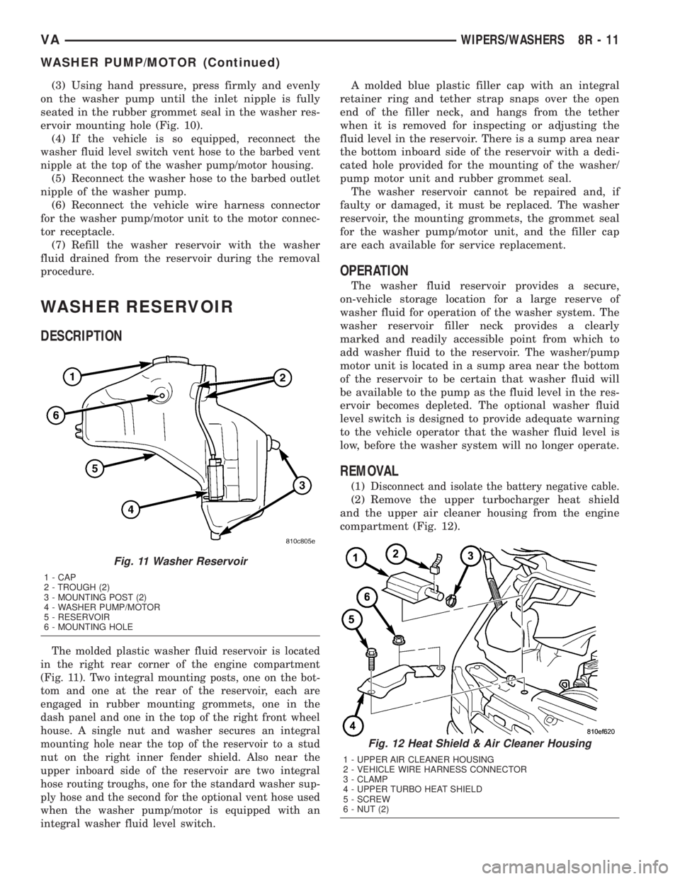
The molded plastic washer fluid reservoir is located
in the right rear corner of the engine compartment
(Fig. 11). Two integral mounting posts, one on the bot-
tom and one at the rear of the reservoir, each are
engaged in rubber mounting grommets, one in the
dash panel and one in the top of the right front wheel
house. A single nut and washer secures an integral
mounting hole near the top of the reservoir to a stud
nut on the right inner fender shield. Also near the
upper inboard side of the reservoir are two integral
hose routing troughs, one for the standard washer sup-
ply hose and the second for the optional vent hose used
when the washer pump/motor is equipped with an
integral washer fluid level switch.
A molded blue plastic filler cap with an integral
retainer ring and tether strap snaps over the open
end of the filler neck, and hangs from the tether
when it is removed for inspecting or adjusting the
fluid level in the reservoir. There is a sump area near
the bottom inboard side of the reservoir with a dedi-
cated hole provided for the mounting of the washer/
pump motor unit and rubber grommet seal.
The washer reservoir cannot be repaired and, if
faulty or damaged, it must be replaced. The washer
reservoir, the mounting grommets, the grommet seal
for the washer pump/motor unit, and the filler cap
are each available for service replacement.
OPERATION
The washer fluid reservoir provides a secure,
on-vehicle storage location for a large reserve of
washer fluid for operation of the washer system. The
washer reservoir filler neck provides a clearly
marked and readily accessible point from which to
add washer fluid to the reservoir. The washer/pump
motor unit is located in a sump area near the bottom
of the reservoir to be certain that washer fluid will
be available to the pump as the fluid level in the res-
ervoir becomes depleted. The optional washer fluid
level switch is designed to provide adequate warning
to the vehicle operator that the washer fluid level is
low, before the washer system will no longer operate.
REMOVAL
(1)Disconnect and isolate the battery negative cable.
(2) Remove the upper turbocharger heat shield
and the upper air cleaner housing from the engine
compartment (Fig. 12).
Fig. 11 Washer Reservoir
1 - CAP
2 - TROUGH (2)
3 - MOUNTING POST (2)
4 - WASHER PUMP/MOTOR
5 - RESERVOIR
6 - MOUNTING HOLE
Fig. 12 Heat Shield & Air Cleaner Housing
1 - UPPER AIR CLEANER HOUSING
2 - VEHICLE WIRE HARNESS CONNECTOR
3 - CLAMP
4 - UPPER TURBO HEAT SHIELD
5 - SCREW
6 - NUT (2)
VAWIPERS/WASHERS 8R - 11
WASHER PUMP/MOTOR (Continued)
Page 311 of 1232
TERMINOLOGY
This is a list of terms and definitions used in the
wiring diagrams.
LHD.................Left Hand Drive Vehicles
RHD ...............Right Hand Drive Vehicles
ATX . . Automatic Transmissions-Front Wheel Drive
MTX . . . Manual Transmissions-Front Wheel Drive
AT....Automatic Transmissions-Rear Wheel Drive
MT .....Manual Transmissions-Rear Wheel Drive
SOHC...........Single Over Head Cam Engine
DOHC..........Double Over Head Cam Engine
Built-Up-Export....... Vehicles Built For Sale In
Markets Other Than North America
Except Built-Up-Export . Vehicles Built For Sale In
North America
DESCRIPTION - CIRCUIT INFORMATION
Each wire shown in the diagrams contains a code
which identifies gage of wire, and color.
WIRE COLOR CODE CHART
COLOR CODE COLOR
BL BLUE
BK BLACK
BR BROWN
DB DARK BLUE
DG DARK GREEN
GY GRAY
LB LIGHT BLUE
LG LIGHT GREEN
OR ORANGE
PK PINK
RD RED
TN TAN
VT VIOLET
WT WHITE
YL YELLOW
* WITH TRACER
DESCRIPTION - SECTION IDENTIFICATION AND
INFORMATION
The wiring diagrams are grouped into individual
sections. If a component is most likely found in a par-
ticular group, it will be shown complete (all wires,
connectors, and pins) within that group. For exam-
ple, the Auto Shutdown Relay is most likely to be
found in Group 30, so it is shown there complete. It
can, however, be shown partially in another group if
it contains some associated wiring.Splice diagrams in Section 8W-70 show the entire
splice and provide references to other sections the
splices serves. Section 8W-70 only contains splice dia-
grams that are not shown in their entirety some-
where else in the wiring diagrams.
Section 8W-80 shows each connector and the cir-
cuits involved with that connector. The connectors
are identified using the name/number on the dia-
gram pages.
WIRING SECTION CHART
GROUP TOPIC
8W-01 thru
8W-09General information and Diagram
Overview
8W-10 thru
8W-19Main Sources of Power and
Vehicle Grounding
8W-20 thru
8W-29Starting and Charging
8W-30 thru
8W-39Powertrain/Drivetrain Systems
8W-40 thru
8W-49Body Electrical items and A/C
8W-50 thru
8W-59Exterior Lighting, Wipers and
Trailer Tow
8W-60 thru
8W-69Power Accessories
8W-70 Splice Information
8W-80 Connector Pin Outs
8W-91 Connector, Ground and Splice
Locations
DESCRIPTION - CONNECTOR, GROUND AND
SPLICE INFORMATION
CAUTION: Not all connectors are serviced. Some
connectors are serviced only with a harness. A typ-
ical example might be the Supplemental Restraint
System connectors. Always check parts availability
before attempting a repair.
IDENTIFICATION
In-line connectors are identified by a number, as
follows:
²In-line connectors located in the engine compart-
ment are C100 series numbers
²In-line connectors located in the Instrument
Panel area are C200 series numbers.
²In-line connectors located in the body are C300
series numbers.
²Jumper harness connectors are C400 series
numbers.
VA8W-01 WIRING DIAGRAM INFORMATION 8W - 01 - 5
WIRING DIAGRAM INFORMATION (Continued)
Page 646 of 1232
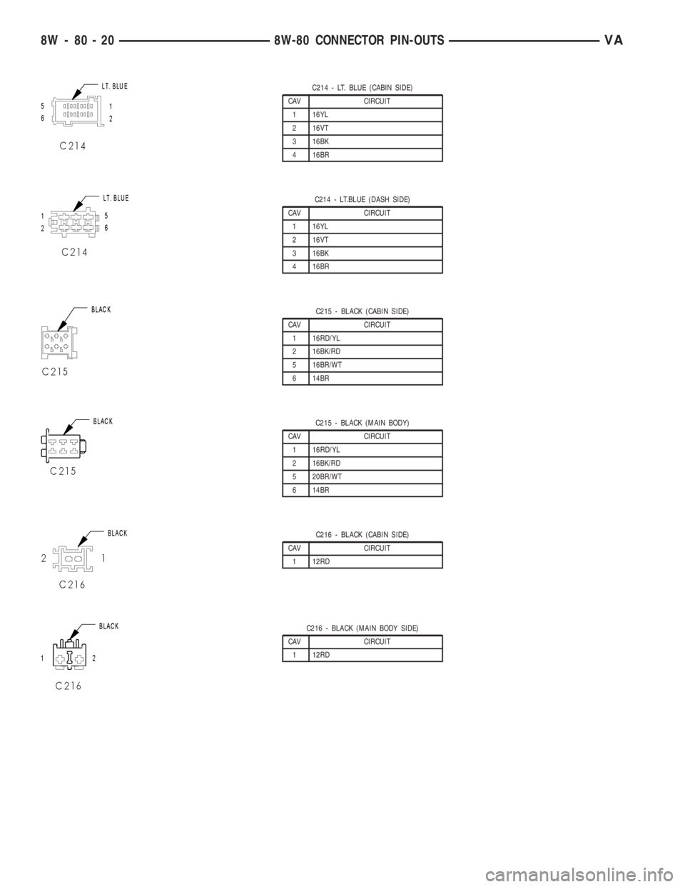
C214 - LT. BLUE (CABIN SIDE)
CAV CIRCUIT
1 16YL
2 16VT
3 16BK
4 16BR
C214 - LT.BLUE (DASH SIDE)
CAV CIRCUIT
1 16YL
2 16VT
3 16BK
4 16BR
C215 - BLACK (CABIN SIDE)
CAV CIRCUIT
1 16RD/YL
2 16BK/RD
5 16BR/WT
6 14BR
C215 - BLACK (MAIN BODY)
CAV CIRCUIT
1 16RD/YL
2 16BK/RD
5 20BR/WT
6 14BR
C216 - BLACK (CABIN SIDE)
CAV CIRCUIT
1 12RD
C216 - BLACK (MAIN BODY SIDE)
CAV CIRCUIT
1 12RD
8W - 80 - 20 8W-80 CONNECTOR PIN-OUTSVA
Page 778 of 1232
PISTON & CONNECTING ROD
DESCRIPTION
The pistons are of a free floating design. Oil jets in
the engine block lubricate and cool the piston and pin
assembly. The connecting rods have a pressed in
place wrist pin bushing which is lubricated by the oil
jets (Fig. 33).
STANDARD PROCEDURE
STANDARD PROCEDURE - CHECKING AND
REPAIRING CONNECTING RODS
NOTE: Connecting rods with blue discoloration,
cross scores or notches must be replaced. Com-
pensate for different weights by milling off the bal-
ancing weight.
(1) Inspect connecting rod for discoloring, cross
scores and notches.NOTE: Connecting rod and bearing cap are marked
in sets and attached with two sleeves.
(2) Bolt connecting rod bearing cap to connecting
rod. Tighten connecting rod bearing caps to initial
specification (Refer to 9 - ENGINE/ENGINE BLOCK/
PISTON & CONNECTING ROD - INSTALLATION).
NOTE: If the maximum permissible diameter is
exceeded, grind off contact surface of connecting
rod bearing cap by a Maximum of 0.02mm.
(3) Using a dial indicator, measure connecting rod
bearing basic bore, repair as necessary (Fig. 34).
NOTE: If excessive wear is present, press in new
connecting rod bushings.
(4) Measure connecting rod bushing inner diame-
ter (Fig. 34).
(5) Inspect wristpin bushing.
(6) Measure piston pin end play in connecting rod
bushing.
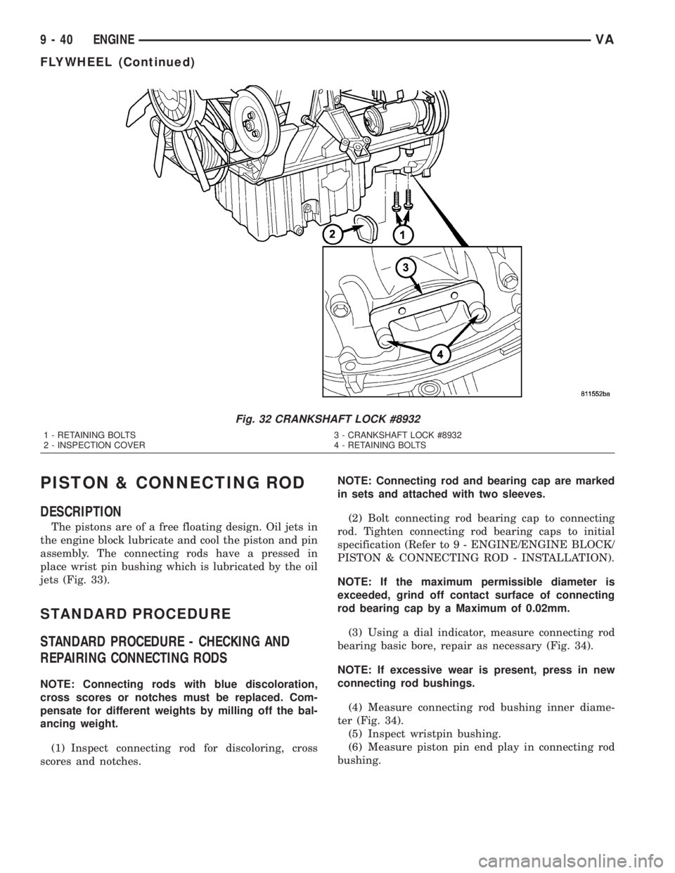
Fig. 32 CRANKSHAFT LOCK #8932
1 - RETAINING BOLTS 3 - CRANKSHAFT LOCK #8932
2 - INSPECTION COVER 4 - RETAINING BOLTS
9 - 40 ENGINEVA
FLYWHEEL (Continued)
Page 1112 of 1232
PAINT
TABLE OF CONTENTS
page page
PAINT
SPECIFICATIONS - PAINT CODES..........74
BASECOAT/CLEARCOAT FINISH
DESCRIPTION.........................74
PAINT TOUCH-UP
DESCRIPTION.........................74STANDARD PROCEDURE - PAINT TOUCH-UP . 75
FINESSE SANDING/BUFFING & POLISH
DESCRIPTION.........................75
PAINT
SPECIFICATIONS - PAINT CODES
EXTERIOR COLORS
EXTERIOR COLOR DAIMLERCHRYSLER
CODE
Steel Blue MB 5389
Brilliant Blue MB 5362
Orchid Green MB 6464
Flame Red MB 3534
Arctic White MB 9147
Black Blue MB 7103
Calcite Yellow MB 1234
Piedmont Red MB 3636
Hycanith Blue MB 5376
Black Gray MB 7103
Stone Gray MB 7160
Silver Gray MB 7708
BASECOAT/CLEARCOAT
FINISH
DESCRIPTION
The original equipment finish is a multi step pro-
cess that involves cleaning, applying electro de-posi-tion (E-coat), anti-chip primer, basecoat, and
clearcoat steps.
On most vehicles a two-part paint application
(basecoat/clearcoat) is used. Color paint that is
applied to primer is called basecoat. The clear coat
protects the basecoat from ultraviolet light and pro-
vides a durable high-gloss finish.
CAUTION: Do not use abrasive chemicals or com-
pounds on painted surfaces. Damage to finish can
result.
Do not use harsh alkaline based cleaning solvents
on painted surfaces. Damage to finish or color can
result.
PAINT TOUCH-UP
DESCRIPTION
When a painted metal surface has been scratched
or chipped, it should be touched-up as soon as possi-
ble to avoid corrosion. For best results, use MOPARt
Scratch Filler/Primer, Touch-Up Paints and Clear Top
Coat.
WARNING: USE AN OSHA APPROVED RESPIRATOR
AND SAFETY GLASSES WHEN SPRAYING PAINT
OR SOLVENTS IN A CONFINED AREA. PERSONAL
INJURY CAN RESULT.
23 - 74 PAINTVA
Page 1175 of 1232
When servicing the air conditioning system, a
R-134a refrigerant recovery/recycling/charging sta-
tion that meets SAE Standard J2210 must be used.
Contact an automotive service equipment supplier for
refrigerant recovery/recycling/charging equipment.
Refer to the operating instructions supplied by the
equipment manufacturer for proper care and use of
this equipment.
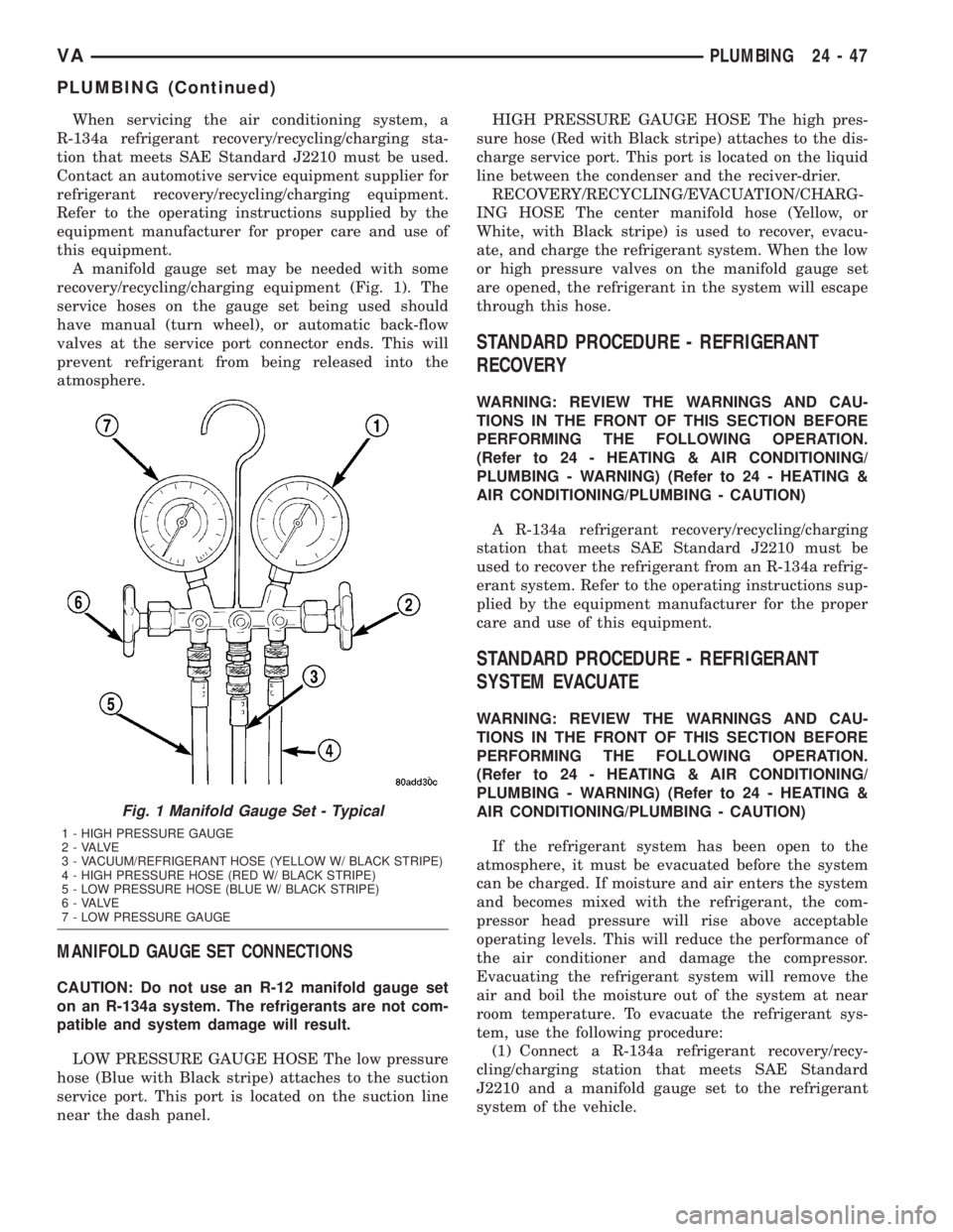
A manifold gauge set may be needed with some
recovery/recycling/charging equipment (Fig. 1). The
service hoses on the gauge set being used should
have manual (turn wheel), or automatic back-flow
valves at the service port connector ends. This will
prevent refrigerant from being released into the
atmosphere.
MANIFOLD GAUGE SET CONNECTIONS
CAUTION: Do not use an R-12 manifold gauge set
on an R-134a system. The refrigerants are not com-
patible and system damage will result.
LOW PRESSURE GAUGE HOSE The low pressure
hose (Blue with Black stripe) attaches to the suction
service port. This port is located on the suction line
near the dash panel.HIGH PRESSURE GAUGE HOSE The high pres-
sure hose (Red with Black stripe) attaches to the dis-
charge service port. This port is located on the liquid
line between the condenser and the reciver-drier.
RECOVERY/RECYCLING/EVACUATION/CHARG-
ING HOSE The center manifold hose (Yellow, or
White, with Black stripe) is used to recover, evacu-
ate, and charge the refrigerant system. When the low
or high pressure valves on the manifold gauge set
are opened, the refrigerant in the system will escape
through this hose.
STANDARD PROCEDURE - REFRIGERANT
RECOVERY
WARNING: REVIEW THE WARNINGS AND CAU-
TIONS IN THE FRONT OF THIS SECTION BEFORE
PERFORMING THE FOLLOWING OPERATION.
(Refer to 24 - HEATING & AIR CONDITIONING/
PLUMBING - WARNING) (Refer to 24 - HEATING &
AIR CONDITIONING/PLUMBING - CAUTION)
A R-134a refrigerant recovery/recycling/charging
station that meets SAE Standard J2210 must be
used to recover the refrigerant from an R-134a refrig-
erant system. Refer to the operating instructions sup-
plied by the equipment manufacturer for the proper
care and use of this equipment.
STANDARD PROCEDURE - REFRIGERANT
SYSTEM EVACUATE
WARNING: REVIEW THE WARNINGS AND CAU-
TIONS IN THE FRONT OF THIS SECTION BEFORE
PERFORMING THE FOLLOWING OPERATION.
(Refer to 24 - HEATING & AIR CONDITIONING/
PLUMBING - WARNING) (Refer to 24 - HEATING &
AIR CONDITIONING/PLUMBING - CAUTION)
If the refrigerant system has been open to the
atmosphere, it must be evacuated before the system
can be charged. If moisture and air enters the system
and becomes mixed with the refrigerant, the com-
pressor head pressure will rise above acceptable
operating levels. This will reduce the performance of
the air conditioner and damage the compressor.
Evacuating the refrigerant system will remove the
air and boil the moisture out of the system at near
room temperature. To evacuate the refrigerant sys-
tem, use the following procedure:
(1) Connect a R-134a refrigerant recovery/recy-
cling/charging station that meets SAE Standard
J2210 and a manifold gauge set to the refrigerant
system of the vehicle.
Fig. 1 Manifold Gauge Set - Typical
1 - HIGH PRESSURE GAUGE
2 - VALVE
3 - VACUUM/REFRIGERANT HOSE (YELLOW W/ BLACK STRIPE)
4 - HIGH PRESSURE HOSE (RED W/ BLACK STRIPE)
5 - LOW PRESSURE HOSE (BLUE W/ BLACK STRIPE)
6 - VALVE
7 - LOW PRESSURE GAUGE
VAPLUMBING 24 - 47
PLUMBING (Continued)