2005 MERCEDES-BENZ SPRINTER keyless entry
[x] Cancel search: keyless entryPage 121 of 1232
ELECTRONIC CONTROL MODULES
TABLE OF CONTENTS
page page
CENTRAL TIMER MODULE
DESCRIPTION..........................1
OPERATION............................2
DIAGNOSIS AND TESTING - CENTRAL TIMER
MODULE.............................2
REMOVAL.............................2
INSTALLATION..........................2
CONTROLLER ANTILOCK BRAKE
DESCRIPTION..........................3
REMOVAL.............................3INSTALLATION..........................3
ENGINE CONTROL MODULE
DESCRIPTION..........................3
REMOVAL.............................4
INSTALLATION..........................4
TRANSMISSION CONTROL MODULE
DESCRIPTION..........................5
OPERATION............................5
STANDARD PROCEDURE - TCM ADAPTATION . 8
CENTRAL TIMER MODULE
DESCRIPTION
The central timer module (CTM) is located beneath
the driver seat. The CTM uses information carried on
the programmable communications interface (PCI)
data bus network along with many hard wired inputs
to monitor many sensor and switch inputs. In
response to those inputs, the circuitry and program-
ming of the CTM allow it to supply the vehicle occu-
pants with audible and visual information, and to
control and integrate many functions and features of
the vehicle through both hard wired outputs and the
transmission of message outputs to other modules in
the vehicle over the PCI data bus.
The features that the CTM supports or controls
include the following:
²Central Locking- The CTM on vehicles
equipped with the optional Vehicle Theft Security
System (VTSS) includes a central locking/unlocking
feature.
²Enhanced Accident Response- The CTM pro-
vides an optional enhanced accident response fea-
ture. This is a programmable feature.
²Panic Mode- The CTM provides support for
the optional RKE system panic mode including horn,
headlamp, and park lamp flash features.
²Power Lock Control- The CTM provides the
optional power lock system features, including sup-
port for the automatic door lock and door lock inhibit
modes.²Programmable Features- The CTM provides
support for certain programmable features.
²Remote Keyless Entry- The CTM provides
the optional Remote Keyless Entry (RKE) system fea-
tures, including support for the RKE Lock (with
optional horn and park lamps flash), Unlock (with
park lamps flash, driver-door-only unlock, and
unlock-all-doors), Panic, and illuminated entry
modes, as well as the ability to be programmed to
recognize up to four RKE transmitters. The RKE
horn, driver-door-only unlock, and unlock-all-doors
features are programmable.
²Vehicle Theft Security System- The CTM
provides control of the optional Vehicle Theft Secu-
rity System (VTSS) features, including support for
the central locking/unlocking mode and control of the
Security indicator in the instrument cluster.
Hard wired circuitry connects the CTM to the elec-
trical system of the vehicle. Refer to the appropriate
wiring information.
Many of the features in the vehicle controlled or
supported by the CTM are programmable using the
DRBIIItscan tool. However, if any of the CTM hard-
ware components are damaged or faulty, the entire
CTM unit must be replaced. The hard wired inputs
or outputs of all CTM versions can be diagnosed
using conventional diagnostic tools and methods;
however, for diagnosis of the CTM or the PCI data
bus, the use of a DRBIIItscan tool is required. Refer
to the appropriate diagnostic information.
VAELECTRONIC CONTROL MODULES 8E - 1
Page 233 of 1232
POWER SYSTEMS
TABLE OF CONTENTS
page page
POWER LOCKS............................ 1
POWER MIRRORS......................... 3POWER WINDOWS......................... 5
POWER LOCKS
TABLE OF CONTENTS
page page
POWER LOCKS
DESCRIPTION..........................1
DOOR LOCK MOTOR
REMOVAL.............................1
INSTALLATION..........................1
REMOTE KEYLESS ENTRY TRANSMITTER
DESCRIPTION..........................2MASTER LOCK SWITCH
DESCRIPTION..........................2
DIAGNOSIS AND TESTING - MASTER LOCK
SWITCH.............................2
REMOVAL.............................2
INSTALLATION..........................2
POWER LOCKS
DESCRIPTION
CENTRAL LOCKING
The central locking system locks all vehicle doors if
any door is locked from the inside or mechanically
locked with the key from the outside. the master door
lock switch on the instrument panel enables the
operator to lock/unlock all doors.
REMOTE KEYLESS ENTRY
The SKREEM is a combination of the Remote Key-
less Entry (RKE) module and the Sentry Key Immo-
bilizer (SKIM) module. It is located behind the
instrument cluster and has an antenna that mounts
to the A-pillar.
AUTO DOOR LOCKS
Whenever the engine is started, the CTM receivers
a message to lock all doors except the drivers door.
This is accomplished through a relay. The relay is
controlled by the Instrument Cluster which receives
a command from the ECM.
ACCIDENT RESPONSE
The CTM is hardwired to the Airbag Control Mod-
ule through the Enhanced Accident Report Driver cir-
cuit. Anytime the vehicles airbags are deployed, the
CTM will unlock all doors and a ªcrashº DTC will be
stored in memory. The door locks will be inoperative
until that code is cleared.
DOOR LOCK MOTOR
REMOVAL
(1) Disconnect and isolate the battery negative
cable.
(2) Remove the door trim panel.
(3) Remove the door lock.
(4) Remove the door lock motor from the door lock.
INSTALLATION
(1) Install the door lock motor to the door lock.
(2) Install the door lock.
(3) Install the door trim panel.
(4) Connect the battery negative cable.
VAPOWER SYSTEMS 8N - 1
Page 234 of 1232
REMOTE KEYLESS ENTRY
TRANSMITTER
DESCRIPTION
Pressing the unlock button on the transmitter will
unlock the drivers door, pressing it a second time
within 2.5 seconds will unlock all other doors. The
transmitter has a range of 10 meters. A key is inte-
gral to the transmitter.
When a transmitter is lost, it is necessary to dis-
able the affected transmitter so that it can no longer
be used to operate the vehicle. It will then be neces-
sary to program a new transmitter to the vehicle.
MASTER LOCK SWITCH
DESCRIPTION
The master lock switch is a momentary contact
switch. Pressing the once in the up direction unlocks
the driver door. Pressing it again in the same direc-
tion unlocks all doors. Pressing the button in the
down direction locks all doors.
DIAGNOSIS AND TESTING - MASTER LOCK
SWITCH
(1) Disconnect and isolate the battery negative
cable.
(2) Remove the switch to be tested.
(3) Using an ohmmeter, test switch for continuity
(Fig. 1).
(4) If test results are not obtained as shown in the
test table, replace the switch.
MASTER LOCK SWITCH
SWITCH
POSITIONCONTINUITY BETWEEN
OPEN 4 AND 7
4 AND 10
7 AND 10
LOCK/UNLOCK 3 AND 4
3 AND 7
3 AND 10
4 AND 7
4 AND 10
4 AND 8
7 AND 8
7 AND 10
REMOVAL
(1) Disconnect and isolate the battery negative
cable.
(2) Remove the instrument panel center bezel
(Refer to 23 - BODY/INSTRUMENT PANEL/IN-
STRUMENT PANEL CENTER BEZEL - REMOVAL).
(3) Remove the central locking switch from the
bezel (Fig. 2).
INSTALLATION
(1) Install switch to bezel.
(2) Install instrument panel center bezel (Refer to
23 - BODY/INSTRUMENT PANEL/INSTRUMENT
PANEL CENTER BEZEL - INSTALLATION).
(3) Connect battery negative cable.Fig. 1 POWER LOCK SWITCH
Fig. 2 POWER LOCK SWITCH
1 - CENTRAL LOCKING SWITCH
2 - INSTRUMENT PANEL
8N - 2 POWER LOCKSVA
Page 278 of 1232
INTRUSION SENSOR
REMOVAL
(1) Disconnect and isolate the battery negative
cable.
(2) Insert the tip of a small flat-bladed screwdriver
into the notch on one edge of the dome lamp/intru-
sion sensor unit housing to depress the retainer clip
and pull that edge of the lamp away from its mount-
ing location (Fig. 1).
(3) Pull the dome lamp/intrusion sensor unit from
its mounting location far enough to access and dis-
connect the vehicle wire harness from the lamp con-
nector receptacle.
(4) Remove the dome lamp/intrusion sensor unit
from its mounting location.
INSTALLATION
(1) Position the dome lamp/intrusion sensor unit to
its mounting location.
(2) Reconnect the vehicle wire harness connector
to the dome lamp/intrusion sensor unit connector
receptacle.
(3) Position the edge of the dome lamp/intrusion
sensor unit housing opposite from the retainer clip
into the mounting hole.
(4) Push firmly and evenly on the notched edge of
the dome lamp/intrusion sensor unit housing until
the retainer clip latches into place.
(5) Connect the battery negative cable.
SECURITY SYSTEM MODULE
REMOVAL
(1) Disconnect and isolate the battery negative
cable.
(2) Remove driver seat cushion.
(3) Remove mounting fasteners.
(4) Disconnect wire harness connector.
INSTALLATION
(1) Connect wire harness connector.
(2) Position module. Install and tighten mounting
fasteners.
(3) Install driver seat cushion.
(4) Connect battery negative cable.
SENTRY KEY REMOTE ENTRY
MODULE
DESCRIPTION
The Sentry Key Remote Entry Module (SKREEM)
(Fig. 2) performs the functions of the Sentry Key
Immobilizer Module (SKIM) and the Remote Keyless
Entry (RKE) module.
Fig. 1 DOME LAMP/INTRUSION SENSOR
1 - NOTCH
2 - SENSOR (3)
3 - HOUSING
4 - SWITCH (2)
Fig. 2 SENTRY KEY REMOTE ENTRY MODULE
(SKREEM)
8Q - 2 VEHICLE THEFT SECURITYVA
Page 279 of 1232
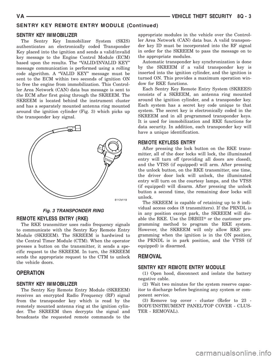
SENTRY KEY IMMOBILIZER
The Sentry Key Immobilizer System (SKIS)
authenticates an electronically coded Transponder
Key placed into the ignition and sends a valid/invalid
key message to the Engine Control Module (ECM)
based upon the results. The ªVALID/INVALID KEYº
message communication is performed using a rolling
code algorithm. A ªVALID KEYº message must be
sent to the ECM within two seconds of ignition ON
to free the engine from immobilization. This Control-
ler Area Network (CAN) data bus message is sent to
the ECM after first going through the SKREEM. The
SKREEM is located behind the instrument cluster
and has a separately mounted antenna ring mounted
around the ignition cylinder (Fig. 3) which picks up
the transponder key signal.
REMOTE KEYLESS ENTRY (RKE)
The RKE transmitter uses radio frequency signals
to communicate with the Sentry Key Remote Entry
Module (SKREEM). The SKREEM is hardwired to
the Central Timer Module (CTM). When the operator
presses a button on the transmitter, it sends a spe-
cific request to the SKREEM. In turn, the SKREEM
sends the appropriate request to the CTM to unlock
the vehicle doors.
OPERATION
SENTRY KEY IMMOBILIZER
The Sentry Key Remote Entry Module (SKREEM)
receives an encrypted Radio Frequency (RF) signal
from the transponder key which is read by the
remotely mounted antenna ring at the ignition cylin-
der. The SKREEM then decrypts the signal and
broadcasts the requested remote commands to theappropriate modules in the vehicle over the Control-
ler Area Network (CAN) data bus. A valid transpon-
der key ID must be incorporated into the RF signal
in order for the SKREEM to pass the message on to
the appropriate modules.
Automatic transponder key synchronization is done
by the SKREEM if a valid transponder key is
inserted into the ignition cylinder, and the ignition is
turned ON. This provides a maximum operation win-
dow for RKE functions.
Each Sentry Key Remote Entry System (SKREES)
consists of a SKREEM, an antenna ring mounted
around the ignition cylinder, and a transponder key.
Each system has a secret key code unique to that
system. The secret key is electronically coded in the
SKREEM and in all programmed transponder keys.
It is used for immobilization and RKE functions for
data security. In addition, each transponder key will
have a unique identification.
REMOTE KEYLESS ENTRY
After pressing the lock button on the RKE trans-
mitter, all of the door locks will lock, the illuminated
entry will turn off (providing all doors are closed),
and the VTSS (if equipped) will arm. After pressing
the unlock button, on the RKE transmitter, one time,
the driver door lock will unlock, the illuminated
entry will turn on the courtesy lamps, and the VTSS
(if equipped) will disarm. After pressing the unlock
button a second time, the remaining door locks will
unlock.
The SKREEM is capable of retaining up to 8 indi-
vidual access codes (8 transmitters). If the PRNDL is
in any position except park, the SKREEM will dis-
able the RKE. Use the DRBIIItor the customer pro-
gramming method to program the RKE system.
However, the SKREEM will only allow RKE pro-
gramming when the ignition is in the ON position,
the PRNDL is in park position, and the VTSS (if
equipped) is disarmed.
REMOVAL
SENTRY KEY REMOTE ENTRY MODULE
(1) Open hood, disconnect and isolate the battery
negative cable.
(2) Wait two minutes for the system reserve capac-
itor to discharge before beginning any system or com-
ponent service.
(3) Remove top cover - cluster (Refer to 23 -
BODY/INSTRUMENT PANEL/TOP COVER - CLUS-
TER - REMOVAL).
Fig. 3 TRANSPONDER RING
VAVEHICLE THEFT SECURITY 8Q - 3
SENTRY KEY REMOTE ENTRY MODULE (Continued)
Page 281 of 1232
TRANSPONDER KEY
DESCRIPTION
The Sentry Key Immobilizer System (SKIS) which
communicates with the Sentry Key Remote Entry
Module (SKREEM), uses a transponder chip that is
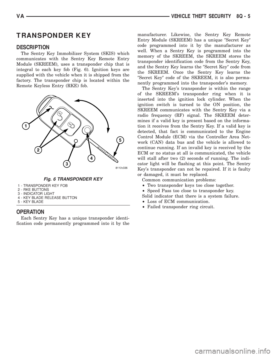
integral to each key fob (Fig. 6). Ignition keys are
supplied with the vehicle when it is shipped from the
factory. The transponder chip is located within the
Remote Keyless Entry (RKE) fob.
OPERATION
Each Sentry Key has a unique transponder identi-
fication code permanently programmed into it by themanufacturer. Likewise, the Sentry Key Remote
Entry Module (SKREEM) has a unique9Secret Key9
code programmed into it by the manufacturer as
well. When a Sentry Key is programmed into the
memory of the SKREEM, the SKREEM stores the
transponder identification code from the Sentry Key,
and the Sentry Key learns the9Secret Key9code from
the SKREEM. Once the Sentry Key learns the
9Secret Key9code of the SKREEM, it is also perma-
nently programmed into the transponder's memory.
The Sentry Key's transponder is within the range
of the SKREEM's transponder ring when it is
inserted into the ignition lock cylinder. When the
ignition switch is turned to the ON position, the
SKREEM communicates with the Sentry Key via a
radio frequency (RF) signal. The SKREEM deter-
mines if a valid key is present based on the informa-
tion it receives from the Sentry Key. If a valid key is
detected, that fact is communicated to the Engine
Control Module (ECM) via the Controller Area Net-
work (CAN) data bus and the vehicle is allowed to
continue running. If an invalid key is received by the
ECM or no status at all is communicated, the vehicle
will stall after two (2) seconds of running. The indi-
cator light will be flashing at this point. The Sentry
Key's transponder can not be repaired. If it is faulty
or damaged, it must be replaced.
Common communication problems:
²Two transponder keys too close together.
²Speed Pass too close to transponder key.
Solid indicator that there is a system failure.
²Loss of ECM communication.
²Failed transponder ring circuit.
Fig. 6 TRANSPONDER KEY
1 - TRANSPONDER KEY FOB
2 - RKE BUTTONS
3 - INDICATOR LIGHT
4 - KEY BLADE RELEASE BUTTON
5 - KEY BLADE
VAVEHICLE THEFT SECURITY 8Q - 5
Page 629 of 1232
Component Page
Panic Alarm Switch................. 8W-80-53
Parking Brake Switch............... 8W-80-53
Power Mirror Motor-Driver........... 8W-80-53
Power Mirror Motor-Passenger......... 8W-80-53
Power Mirror Switch................ 8W-80-53
Power Window Motor-Driver.......... 8W-80-54
Power Window Motor-Passenger........ 8W-80-54
Power Window Switch-Driver.......... 8W-80-54
Power Window Switch-Master......... 8W-80-54
Power Window Switch-Passenger....... 8W-80-54
Radio Antenna..................... 8W-80-55
Radio C1.......................... 8W-80-55
Radio C2.......................... 8W-80-55
Radio/Cellular Antenna.............. 8W-80-55
Reading Lamp Connector............. 8W-80-56
RECIRCULATED AIR SOLENOID
Valve.......................... 8W-80-56
Refrigerant Pressure Sensor........... 8W-80-56
Remote Keyless Entry Antenna........ 8W-80-56
Roof Fan Motor..................... 8W-80-56
Seat Belt Switch.................... 8W-80-57
Seat Belt Tensioner-Driver............ 8W-80-57
Seat Belt Tensioner-Passenger......... 8W-80-57
Security System Module C1........... 8W-80-57
Security System Module C2........... 8W-80-58
Sentry Key Remote Entry Module
(Skreem)........................ 8W-80-58
Shifter Assembly................... 8W-80-58
Siren............................. 8W-80-59
Speaker-Left Front Door Assembly C1 . . . 8W-80-59
Speaker-Left Front Door Assembly C2 . . . 8W-80-59
Speaker-Left Rear.................. 8W-80-59
Speaker-Right Front Door............ 8W-80-59
Speaker-Right Rear................. 8W-80-60Component Page
Speed Control Switch................ 8W-80-60
Tail Lamp Assembly-Left............. 8W-80-60
Tail Lamp Assembly-Right............ 8W-80-60
TCS Switch (ASR).................. 8W-80-60
Temperature Switch................. 8W-80-61
Time Delay Relay................... 8W-80-61
Towing/Intrusion Sensor On/Off Switch . . 8W-80-61
Trailer Tow Connector............... 8W-80-61
Trailer Tow Control Module C1........ 8W-80-62
Trailer Tow Control Module C2........ 8W-80-62
Transmission Control Module C1....... 8W-80-62
Transmission Control Module C2....... 8W-80-62
Transmission Solenoid Assembly....... 8W-80-63
Turn Signal No. 1-Left Front.......... 8W-80-63
Turn Signal No. 1-Right Front......... 8W-80-63
Turn Signal No. 2-Left Front.......... 8W-80-63
Turn Signal No. 2-Right Front......... 8W-80-64
Warm Air Auxiliary Heater Assembly C1 . 8W-80-64
Warm Air Auxiliary Heater Assembly C2 . 8W-80-64
Washer Pump Motor-Front............ 8W-80-64
Water Cycle Valve................... 8W-80-64
Water In Fuel Sensor................ 8W-80-65
Wheel Speed Sensor-Left Front........ 8W-80-65
Wheel Speed Sensor-Left Rear......... 8W-80-65
Wheel Speed Sensor-Right Front....... 8W-80-65
Wheel Speed Sensor-Right Rear........ 8W-80-65
Window Defogger Module-Rear......... 8W-80-66
Window Defogger Switch-Rear......... 8W-80-66
Window Defogger-Left Rear........... 8W-80-66
Window Defogger-Right Rear.......... 8W-80-66
Wiper Motor-Front.................. 8W-80-66
Wiper/Turn Signal/Engine Start Control
Module (Fuse Block No. 1).......... 8W-80-67
VA8W-80 CONNECTOR PIN-OUTS 8W - 80 - 3
Page 682 of 1232
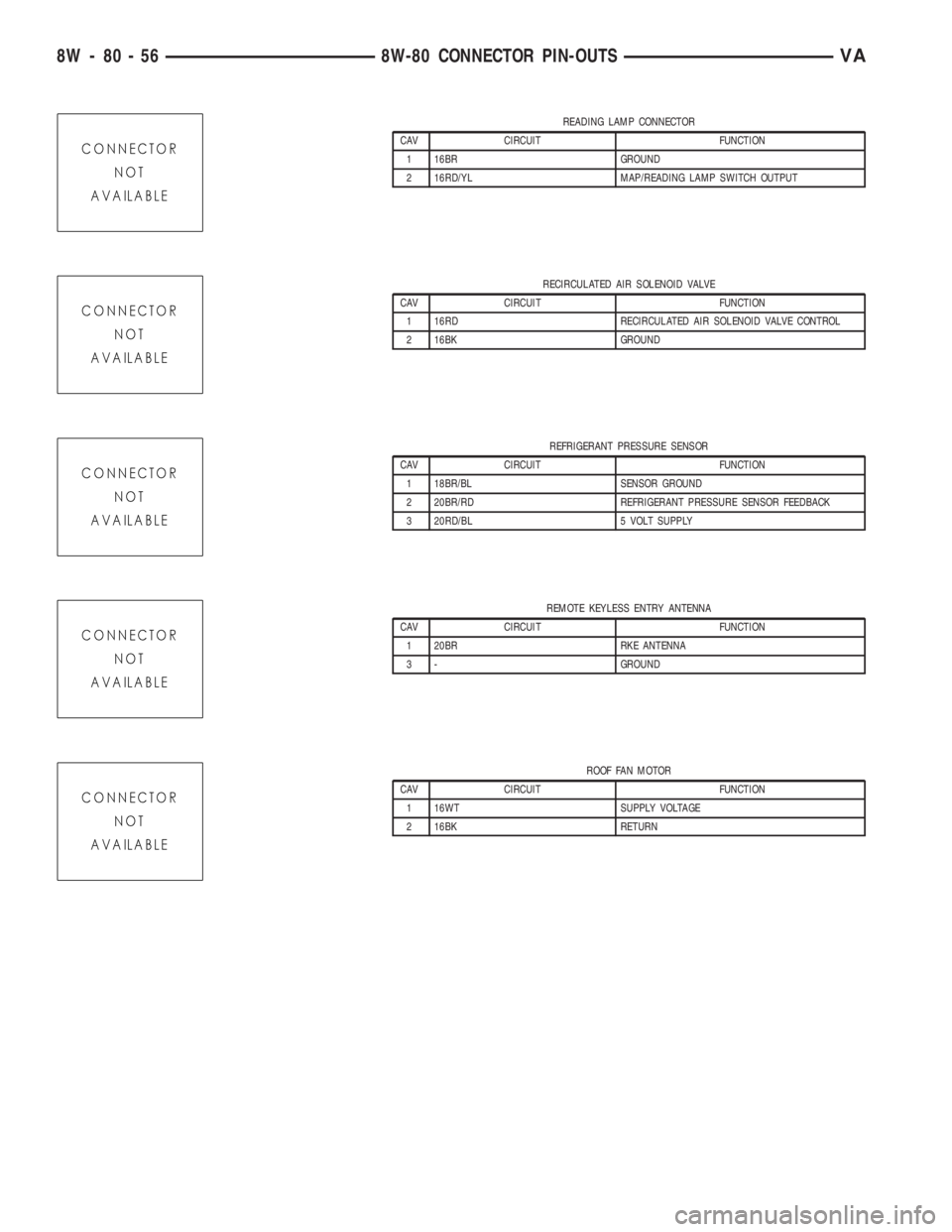
READING LAMP CONNECTOR
CAV CIRCUIT FUNCTION
1 16BR GROUND
2 16RD/YL MAP/READING LAMP SWITCH OUTPUT
RECIRCULATED AIR SOLENOID VALVE
CAV CIRCUIT FUNCTION
1 16RD RECIRCULATED AIR SOLENOID VALVE CONTROL
2 16BK GROUND
REFRIGERANT PRESSURE SENSOR
CAV CIRCUIT FUNCTION
1 18BR/BL SENSOR GROUND
2 20BR/RD REFRIGERANT PRESSURE SENSOR FEEDBACK
3 20RD/BL 5 VOLT SUPPLY
REMOTE KEYLESS ENTRY ANTENNA
CAV CIRCUIT FUNCTION
1 20BR RKE ANTENNA
3 - GROUND
ROOF FAN MOTOR
CAV CIRCUIT FUNCTION
1 16WT SUPPLY VOLTAGE
2 16BK RETURN
8W - 80 - 56 8W-80 CONNECTOR PIN-OUTSVA