2005 MERCEDES-BENZ SPRINTER weight
[x] Cancel search: weightPage 3 of 1232
INTRODUCTION
TABLE OF CONTENTS
page page
VEHICLE IDENTIFICATION NUMBER
DESCRIPTION..........................1
INTERNATIONAL SYMBOLS
DESCRIPTION..........................2
FASTENER IDENTIFICATION
DESCRIPTION..........................2
FASTENER USAGE
DESCRIPTION - FASTENER USAGE.........5THREADED HOLE REPAIR
DESCRIPTION - THREADED HOLE REPAIR....5
METRIC SYSTEM
DESCRIPTION..........................5
TORQUE REFERENCES
DESCRIPTION..........................7
VEHICLE IDENTIFICATION
NUMBER
DESCRIPTION
The Vehicle Identification Number (VIN) plate is
located on the lower windshield fence next to the left
a-pillar. The VIN contains 17 characters that provide
data concerning the vehicle. Refer to the VIN
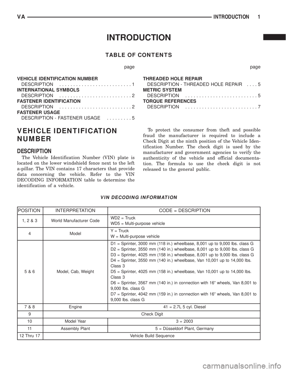
DECODING INFORMATION table to determine the
identification of a vehicle.To protect the consumer from theft and possible
fraud the manufacturer is required to include a
Check Digit at the ninth position of the Vehicle Iden-
tification Number. The check digit is used by the
manufacturer and government agencies to verify the
authenticity of the vehicle and official documenta-
tion. The formula to use the check digit is not
released to the general public.
VIN DECODING INFORMATION
POSITION INTERPRETATION CODE = DESCRIPTION
1,2&3 World Manufacturer CodeWD2 = Truck
WD5 = Multi-purpose vehicle
4 ModelY = Truck
W = Multi-purpose vehicle
5 & 6 Model, Cab, WeightD1 = Sprinter, 3000 mm (118 in.) wheelbase, 8,001 up to 9,000 lbs. class G
D2 = Sprinter, 3550 mm (140 in.) wheelbase, 8,001 up to 9,000 lbs. class G
D3 = Sprinter, 4025 mm (158 in.) wheelbase, 8,001 up to 9,000 lbs. class G
D4 = Sprinter, 3550 mm (140 in.) wheelbase, Van 10,001 up to 14,000 lbs.
Class 3
D5 = Sprinter, 4025 mm (158 in.) wheelbase, Van 10,001 up to 14,000 lbs.
Class 3
D6 = Sprinter, 3567 mm (140 in.) in connection with 169wheels, Van 8,001 to
9,000 lbs. class G
D7 = Sprinter, 4042 mm (159 in.) in connection with 169wheels, Van 8,001 to
9,000 lbs. class G
7 & 8 Engine 41 = 2.7L 5 cyl. Diesel
9 Check Digit
10 Model Year 3 = 2003
11 Assembly Plant 5 = Dîsseldorf Plant, Germany
12 Thru 17 Vehicle Build Sequence
VAINTRODUCTION 1
Page 18 of 1232
MAINTENANCE - WITH ASSYST MAINTENANCE
COMPUTER
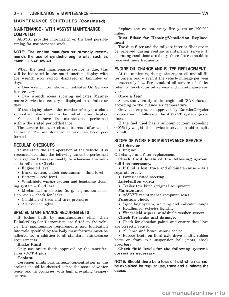
ASSYST provides information on the best possible
timing for maintenance work.
NOTE: The engine manufacturer strongly recom-
mends the use of synthetic engine oils, such as
TMobil 1 SAE 0W-40.
When the next maintenance service is due, this
will be indicated in the multi-function display with
the wrench icon symbol displayed in km/miles or
days.
²One wrench icon showing indicates Oil Service
is necessary.
²Two wrench icons showing indicates Mainte-
nance Service is necessary ± displayed in km/miles or
days.
If the display shows the number of days, a clock
symbol will also appear in the multi-function display.
You should have the maintenance performed
within the stated period/distance.
The service indicator should be reset after an oil
service and/or maintenance service has been per-
formed.
REGULAR CHECK-UPS
To maintain the safe operation of the vehicle, it is
recommended that the following tasks be performed
on a regular basis (i.e. weekly or whenever the vehi-
cle is refueled). Check:
²Engine oil level
²Brake system, clutch mechanism ± fluid level
²Battery ± acid level
²Windshield washer system and headlamp clean-
ing system ± fluid level
²Mechanical assemblies (e. g. engine, transmis-
sion, etc.) ± check for leaks
²Condition of tires and tires pressures
²All exterior lights
SPECIAL MAINTENANCE REQUIREMENTS
If bodies built by manufacturers other than
DaimlerChrysler Corporation are fitted to the vehi-
cle, the maintenance requirements and lubrication
intervals specified by the body manufacturer must be
adhered to, in addition to all standard maintenance
requirements.
Brake Fluid
Only use brake fluids approved by the manufac-
turer (DOT 4 plus).
Coolant
Corrosion inhibitor/antifreeze concentration in the
coolant should be checked before the onset of winter
(once year in countries with high prevailing temper-
atures).Replace the coolant every five years or 100,000
miles.
Dust Filter for Heating/Ventilation Replace-
ment
The dust filter and the tailgate interior filter are to
be renewed during routine maintenance service. If
operating conditions are dusty, these filters should be
renewed more frequently.
ENGINE OIL CHANGE AND FILTER REPLACEMENT
At the minimum, change the engine oil and oil fil-
ter once a year ± even if the vehicle mileage per year
is extremely low. For standard oil service schedules
refer to the chapter oil service and maintenance ser-
vice.
Once a Year
Select the viscosity of the engine oil (SAE classes)
according to the outside air temperature.
Only use engine oil approved by DaimlerChrysler
Corporation if following the ASSYST system guide-
lines.
If the fuel used has a sulphur content exceeding
0.05% by weight, the service intervals should be split
in half.
SCOPE OF WORK FOR MAINTENANCE SERVICE
Oil Service
²Engine:
Oil change and filter replacement
Check fluid levels of the following system,
refill as necessary.
²If fluid is lost, trace and eliminate cause ± as a
separate order.
²Power-assisted steering
Lubrication work:
²Trailer tow hitch (original equipment)
Maintenance
²ASSYST maintenance computer reset
Function check
²Signalling system, warning and indicator lamps
²Headlamps, exterior lighting
²Windshield wipers, windshield washer system
Check for leaks and damage.
²Check for abrasion points and ensure that lines
are correctly routed!
²All lines and hoses, sensor cables
²Rubber boots on front axle drive shafts, rubber
boots on front axle suspension ball joints, shock
absorbers
Check fluid levels for the following systems,
correct as necessary.
NOTE: Should there be a loss of fluid which cannot
be explained by regular use, trace and eliminate the
cause.
0 - 8 LUBRICATION & MAINTENANCEVA
MAINTENANCE SCHEDULES (Continued)
Page 26 of 1232
(2) Install the lower ball joint nut (Fig. 6). Tighten
to 280 N´m (206 ft. lbs.)
(3) Install the strut to the steering knuckle (Fig.
6). Tighten to 185 N´m (136 ft. lbs.).
(4) Install the outer tie rod end to the steering
knuckle (Fig. 6) and tighten the nut to 130 N´m (96
ft. lbs.).
(5) Install the ABS sensor by pushing the sensor
all the way into the knuckle and the sensor will self
adjust when the wheel is turned.
(6) Install the hub/bearing (Refer to 2 - SUSPEN-
SION/FRONT/HUB / BEARING - INSTALLATION).
(7) Install the disc brake caliper adapter with the
brake caliper (Refer to 5 - BRAKES/HYDRAULIC/
MECHANICAL/DISC BRAKE CALIPER ADAPTER -
INSTALLATION).
(8) Install the front wheels (Refer to 22 - TIRES/
WHEELS/WHEELS - INSTALLATION).
(9) Lower the vehicle.
(10) Check and set toe if necessary (Refer to 2 -
SUSPENSION/WHEEL ALIGNMENT - STANDARD
PROCEDURE).
LOWER BALL JOINT
REMOVAL
(1) Raise and support the vehicle.
(2) Remove the front tire and wheel assembly.
(3) Remove the front strut (Refer to 2 - SUSPEN-
SION/FRONT/STRUT - REMOVAL).
(4) Remove the steering knuckle (Refer to 2 - SUS-
PENSION/FRONT/KNUCKLE - REMOVAL).
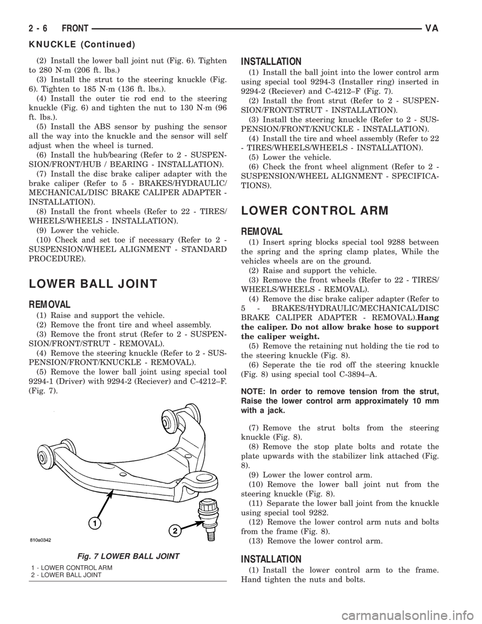
(5) Remove the lower ball joint using special tool
9294-1 (Driver) with 9294-2 (Reciever) and C-4212±F.
(Fig. 7).
INSTALLATION
(1) Install the ball joint into the lower control arm
using special tool 9294-3 (Installer ring) inserted in
9294-2 (Reciever) and C-4212±F (Fig. 7).
(2) Install the front strut (Refer to 2 - SUSPEN-
SION/FRONT/STRUT - INSTALLATION).
(3) Install the steering knuckle (Refer to 2 - SUS-
PENSION/FRONT/KNUCKLE - INSTALLATION).
(4) Install the tire and wheel assembly (Refer to 22
- TIRES/WHEELS/WHEELS - INSTALLATION).
(5) Lower the vehicle.
(6) Check the front wheel alignment (Refer to 2 -
SUSPENSION/WHEEL ALIGNMENT - SPECIFICA-
TIONS).
LOWER CONTROL ARM
REMOVAL
(1) Insert spring blocks special tool 9288 between
the spring and the spring clamp plates, While the
vehicles wheels are on the ground.
(2) Raise and support the vehicle.
(3) Remove the front wheels (Refer to 22 - TIRES/
WHEELS/WHEELS - REMOVAL).
(4) Remove the disc brake caliper adapter (Refer to
5 - BRAKES/HYDRAULIC/MECHANICAL/DISC
BRAKE CALIPER ADAPTER - REMOVAL).Hang
the caliper. Do not allow brake hose to support
the caliper weight.
(5) Remove the retaining nut holding the tie rod to
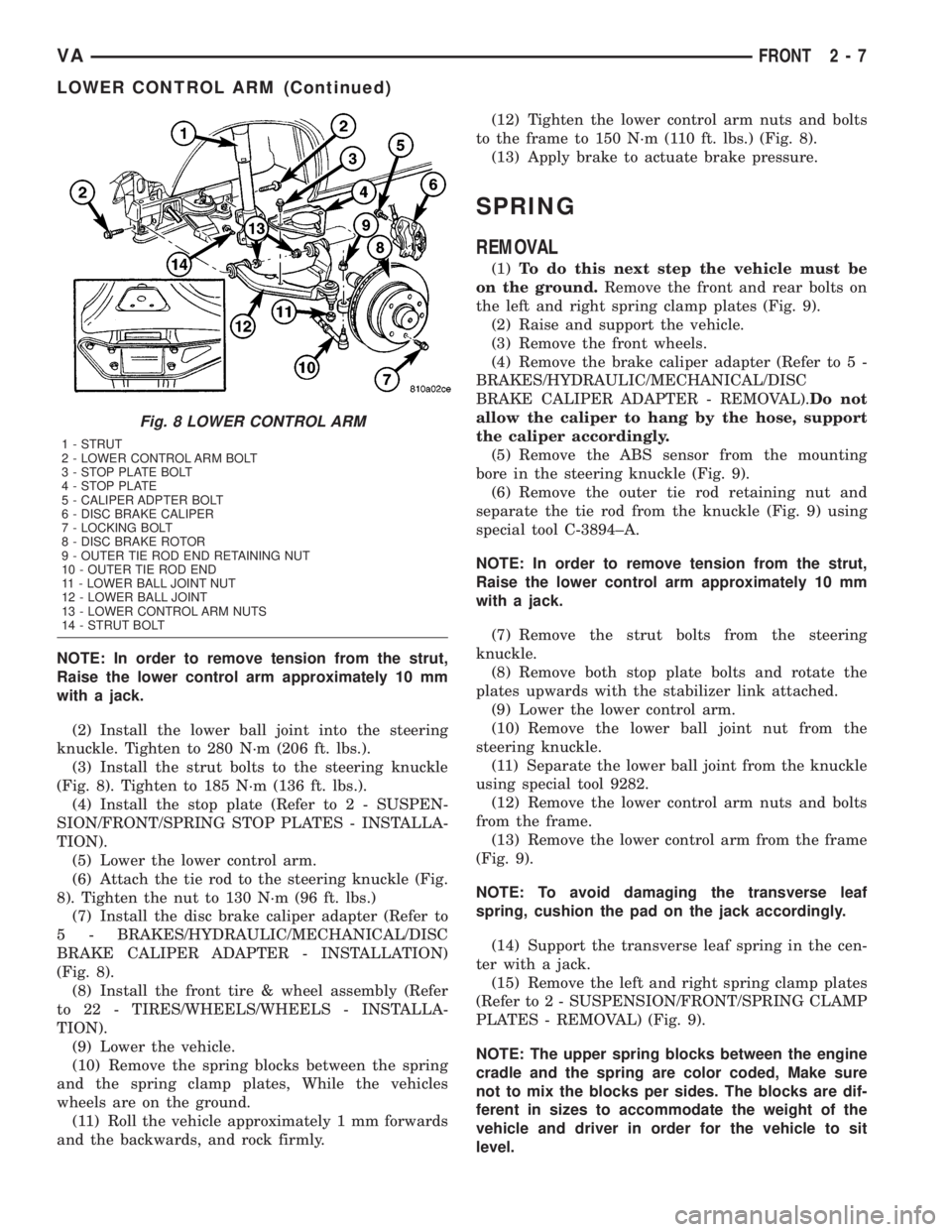
the steering knuckle (Fig. 8).
(6) Seperate the tie rod off the steering knuckle
(Fig. 8) using special tool C-3894±A.
NOTE: In order to remove tension from the strut,
Raise the lower control arm approximately 10 mm
with a jack.
(7) Remove the strut bolts from the steering
knuckle (Fig. 8).
(8) Remove the stop plate bolts and rotate the
plate upwards with the stabilizer link attached (Fig.
8).
(9) Lower the lower control arm.
(10) Remove the lower ball joint nut from the
steering knuckle (Fig. 8).
(11) Separate the lower ball joint from the knuckle
using special tool 9282.
(12) Remove the lower control arm nuts and bolts
from the frame (Fig. 8).
(13) Remove the lower control arm.
INSTALLATION
(1) Install the lower control arm to the frame.
Hand tighten the nuts and bolts.
Fig. 7 LOWER BALL JOINT
1 - LOWER CONTROL ARM
2 - LOWER BALL JOINT
2 - 6 FRONTVA
KNUCKLE (Continued)
Page 27 of 1232
NOTE: In order to remove tension from the strut,
Raise the lower control arm approximately 10 mm
with a jack.
(2) Install the lower ball joint into the steering
knuckle. Tighten to 280 N´m (206 ft. lbs.).
(3) Install the strut bolts to the steering knuckle
(Fig. 8). Tighten to 185 N´m (136 ft. lbs.).
(4) Install the stop plate (Refer to 2 - SUSPEN-
SION/FRONT/SPRING STOP PLATES - INSTALLA-
TION).
(5) Lower the lower control arm.
(6) Attach the tie rod to the steering knuckle (Fig.
8). Tighten the nut to 130 N´m (96 ft. lbs.)
(7) Install the disc brake caliper adapter (Refer to
5 - BRAKES/HYDRAULIC/MECHANICAL/DISC
BRAKE CALIPER ADAPTER - INSTALLATION)
(Fig. 8).
(8) Install the front tire & wheel assembly (Refer
to 22 - TIRES/WHEELS/WHEELS - INSTALLA-
TION).
(9) Lower the vehicle.
(10) Remove the spring blocks between the spring
and the spring clamp plates, While the vehicles
wheels are on the ground.
(11) Roll the vehicle approximately 1 mm forwards
and the backwards, and rock firmly.(12) Tighten the lower control arm nuts and bolts
to the frame to 150 N´m (110 ft. lbs.) (Fig. 8).
(13) Apply brake to actuate brake pressure.
SPRING
REMOVAL
(1)To do this next step the vehicle must be
on the ground.Remove the front and rear bolts on
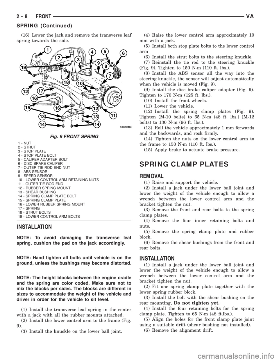
the left and right spring clamp plates (Fig. 9).
(2) Raise and support the vehicle.
(3) Remove the front wheels.
(4) Remove the brake caliper adapter (Refer to 5 -
BRAKES/HYDRAULIC/MECHANICAL/DISC
BRAKE CALIPER ADAPTER - REMOVAL).Do not
allow the caliper to hang by the hose, support
the caliper accordingly.
(5) Remove the ABS sensor from the mounting
bore in the steering knuckle (Fig. 9).
(6) Remove the outer tie rod retaining nut and
separate the tie rod from the knuckle (Fig. 9) using
special tool C-3894±A.
NOTE: In order to remove tension from the strut,
Raise the lower control arm approximately 10 mm
with a jack.
(7) Remove the strut bolts from the steering
knuckle.
(8) Remove both stop plate bolts and rotate the
plates upwards with the stabilizer link attached.
(9) Lower the lower control arm.
(10) Remove the lower ball joint nut from the
steering knuckle.
(11) Separate the lower ball joint from the knuckle
using special tool 9282.
(12) Remove the lower control arm nuts and bolts
from the frame.
(13) Remove the lower control arm from the frame
(Fig. 9).
NOTE: To avoid damaging the transverse leaf
spring, cushion the pad on the jack accordingly.
(14) Support the transverse leaf spring in the cen-
ter with a jack.
(15) Remove the left and right spring clamp plates
(Refer to 2 - SUSPENSION/FRONT/SPRING CLAMP
PLATES - REMOVAL) (Fig. 9).
NOTE: The upper spring blocks between the engine
cradle and the spring are color coded, Make sure
not to mix the blocks per sides. The blocks are dif-
ferent in sizes to accommodate the weight of the
vehicle and driver in order for the vehicle to sit
level.
Fig. 8 LOWER CONTROL ARM
1 - STRUT
2 - LOWER CONTROL ARM BOLT
3 - STOP PLATE BOLT
4 - STOP PLATE
5 - CALIPER ADPTER BOLT
6 - DISC BRAKE CALIPER
7 - LOCKING BOLT
8 - DISC BRAKE ROTOR
9 - OUTER TIE ROD END RETAINING NUT
10 - OUTER TIE ROD END
11 - LOWER BALL JOINT NUT
12 - LOWER BALL JOINT
13 - LOWER CONTROL ARM NUTS
14 - STRUT BOLT
VAFRONT 2 - 7
LOWER CONTROL ARM (Continued)
Page 28 of 1232
(16) Lower the jack and remove the transverse leaf
spring towards the side.
INSTALLATION
NOTE: To avoid damaging the transverse leaf
spring, cushion the pad on the jack accordingly.
NOTE: Hand tighten all bolts until vehicle is on the
ground, unless the bushings may become distorted.
NOTE: The height blocks between the engine cradle
and the spring are color coded, Make sure not to
mix the blocks per sides. The blocks are different in
sizes to accommodate the weight of the vehicle and
driver in order for the vehicle to sit level.
(1) Install the transverse leaf spring in the center
with a jack with all the rubber mounts attached.
(2) Install the lower control arm to the frame (Fig.
9).
(3) Install the knuckle on the lower ball joint.(4) Raise the lower control arm approximately 10
mm with a jack.
(5) Install both stop plate bolts to the lower control
arm
(6) Install the strut bolts to the steering knuckle.
(7) Reinstall the tie rod to the steering knuckle
(Fig. 9). Tighten to 150 N´m (110 ft. lbs.).
(8) Install the ABS sensor all the way into the
steering knuckle, the sensor will adjust automatically
when the vehicle is moved (Fig. 9).
(9) Install the disc brake caliper adapter (Fig. 9).
Tighten to 170 N´m (125 ft. lbs.).
(10) Install the front wheels.
(11) Lower the vehicle.
(12) Install the spring clamp plates (Fig. 9).
Tighten (M-10 bolts) to 65 N´m (48 ft. lbs.) (M-12
bolts) to 130 N´m (96 ft. lbs.).
(13) Roll the vehicle approximately 1 mm forwards
and the backwards, and rock firmly.
(14) Tighten the nuts on the lower control arm to
the frame to 150 N´m (110 ft. lbs.).
(15) Apply brake to actuate brake pressure.
SPRING CLAMP PLATES
REMOVAL
(1) Raise and support the vehicle.
(2) Install a jack under the lower ball joint and
lower the weight of the vehicle enough to allow a
wrench between the lower control arm and the
bracket tighten the nut.
(3) Remove the front and rear bolts to the spring
clamp plates.
(4) Remove the four inner retaining bolts and
nuts.
(5) Remove the spring clamp plate and rubber
block.
(6) Remove the shear bushings from the front and
rear bolts.
INSTALLATION
(1) Install a jack under the lower ball joint and
lower the weight of the vehicle enough to allow a
wrench between the lower control arm and the
bracket tighten the nut.
(2) Fit one spring clamp plate together with the
lower spring rubber block.
(3) Install the bolt with the shear bushing on the
rear mounting,Do not tighten yet.
(4) Install the four retaining bolts for the spring
clamp plate. Tighten to 65 N´m (48 ft.lbs.).
(5) Align the holes for the front clamp plate joint
using a suitable drift (shear bushing not installed).
(6) Remove the alignment drift.
Fig. 9 FRONT SPRING
1 - NUT
2 - STRUT
3 - STOP PLATE
4 - STOP PLATE BOLT
5 - CALIPER ADAPTER BOLT
6 - DISC BRAKE CALIPER
7 - OUTER TIE ROD END NUT
8 - ABS SENSOR
9 - SPEED SENSOR
10 - LOWER CONTROL ARM RETAINING NUTS
11 - OUTER TIE ROD END
12 - RUBBER SPRING MOUNT
13 - SHEAR BUSHING
14 - SPRING CLAMP PLATE BOLT
15 - SPRING CLAMP PLATE
16 - LOWER RUBBER SPRING MOUNT
17 - SPRING
18 - STRUT BOLTS
19 - LOWER CONTROL ARM BOLTS
2 - 8 FRONTVA
SPRING (Continued)
Page 31 of 1232
REAR
TABLE OF CONTENTS
page page
REAR
DESCRIPTION.........................11
DIAGNOSIS AND TESTING - SPRING AND
SHOCK.............................11
SPECIFICATIONS - TORQUE CHART........12
SHOCK
DIAGNOSIS AND TESTING - SHOCK........13
REMOVAL.............................13
INSTALLATION.........................13
SPRING
DESCRIPTION.........................14
OPERATION...........................14
REMOVAL
REMOVAL - (SRW)....................14REMOVAL - (DRW)....................14
INSTALLATION
INSTALLATION - (SRW).................14
INSTALLATION - (DRW).................15
SPRING SHACKLE
REMOVAL.............................15
INSTALLATION.........................15
STABILIZER BAR
REMOVAL.............................15
INSTALLATION.........................15
STABILIZER LINK
REMOVAL.............................16
INSTALLATION.........................16
REAR
DESCRIPTION
The rear suspension is comprised of:
²Shock Absorbers
²Jounce Bumpers
²Stabilizer Bar
²Leaf Springs
²Drive Axle
CAUTION: A vehicle should always be loaded so
the vehicle weight center-line is located immedi-
ately forward of the rear axle. Correct vehicle load-
ing provides proper front tire-to-road contact. This
results in maximum vehicle handling stability and
safety. Incorrect vehicle weight distribution can
cause excessive tire tread wear, spring fatigue or
failure, and erratic steering.
CAUTION: Suspension components with rubber/ure-
thane bushings (except stabilizer bar) should be
tightened with the vehicle at normal ride height. It is
important to have the springs supporting the weight
of the vehicle when the fasteners are torqued. If
springs are not at their normal ride position, vehicle
ride comfort could be affected and premature bush-
ing wear may occur.
DIAGNOSIS AND TESTING - SPRING AND
SHOCK
A knocking or rattling noise from a shock absorber
may be caused by movement between mounting
bushings and metal brackets or attaching compo-
nents. These noises can usually be stopped by tight-
ening the attaching nuts. If the noise persists,
inspect for damaged and worn bushings, and attach-
ing components. Repair as necessary if any of these
conditions exist.
A squeaking noise from the shock absorber may be
caused by the hydraulic valving and may be intermit-
tent. This condition is not repairable and the shock
absorber must be replaced.
The shock absorbers are not refillable or adjust-
able. If a malfunction occurs, the shock absorber
must be replaced. To test a shock absorber, hold it in
an upright position and force the piston in and out of
the cylinder four or five times. The action throughout
each stroke should be smooth and even.
The spring eye and shock absorber bushings do not
require any type of lubrication. Do not attempt to
stop spring bushing noise by lubricating them.
Grease and mineral oil-base lubricants will deterio-
rate the bushing rubber.
If the vehicle is used for severe, off-road operation,
the springs should be examined periodically. Check
for broken and shifted leafs, loose and missing clips,
and broken center bolts. Refer to Spring and Shock
Absorber Diagnosis chart for additional information.
VAREAR 2 - 11
Page 37 of 1232
WHEEL ALIGNMENT
TABLE OF CONTENTS
page page
WHEEL ALIGNMENT
DESCRIPTION.........................17
DIAGNOSIS AND TESTING - PRE-ALIGNMENT
INSPECTION.........................17STANDARD PROCEDURE - TOE
ADJUSTMENT........................19
SPECIFICATIONS.......................19
WHEEL ALIGNMENT
DESCRIPTION
NOTE: Camber and Caster are not adjustable on
this vehicle. (TOE ONLY).
NOTE: Suspension components with rubber/ure-
thane bushings should be tightened with the vehi-
cle at normal ride height. It is important to have the
springs supporting the weight of the vehicle when
the fasteners are torqued. If springs are not at their
normal ride position, vehicle ride comfort could be
affected and premature bushing wear may occur.
Wheel alignment involves the correct positioning of
the wheels in relation to the vehicle. The positioning
is accomplished through suspension and steering
linkage adjustments. An alignment is considered
essential for efficient steering, good directional stabil-
ity and to minimize tire wear. The most important
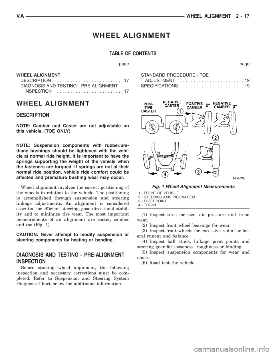
measurements of an alignment are caster, camber
and toe (Fig. 1).
CAUTION: Never attempt to modify suspension or
steering components by heating or bending.
DIAGNOSIS AND TESTING - PRE-ALIGNMENT
INSPECTION
Before starting wheel alignment, the following
inspection and necessary corrections must be com-
pleted. Refer to Suspension and Steering System
Diagnosis Chart below for additional information.(1) Inspect tires for size, air pressure and tread
wear.
(2) Inspect front wheel bearings for wear.
(3) Inspect front wheels for excessive radial or lat-
eral runout and balance.
(4) Inspect ball studs, linkage pivot points and
steering gear for looseness, roughness or binding.
(5) Inspect suspension components for wear and
noise.
(6) Road test the vehicle.
Fig. 1 Wheel Alignment Measurements
1 - FRONT OF VEHICLE
2 - STEERING AXIS INCLINATION
3 - PIVOT POINT
4 - TOE-IN
VAWHEEL ALIGNMENT 2 - 17
Page 42 of 1232
DRIVELINE VIBRATION
Drive Condition Possible Cause Correction
Propeller Shaft Noise 1) Undercoating or other foreign
material on shaft.1) Clean exterior of shaft and wash
with solvent.
2) Loose U-joint clamp screws. 2) Install new clamps and screws
and tighten to proper torque.
3) Loose or bent U-joint yoke or
excessive runout.3) Install new yoke.
4) Incorrect driveline angularity. 4) Measure and correct driveline
angles.
5) Rear spring center bolt not in
seat.5) Loosen spring u-bolts and seat
center bolt.
6) Worn U-joint bearings. 6) Install new U-joint.
7) Propeller shaft damaged or out
of balance.7) Installl new propeller shaft.
8) Broken rear spring. 8) Install new rear spring.
9) Excessive runout or unbalanced
condition.9) Re-index propeller shaft, test,
and evaluate.
10) Excessive drive pinion gear
shaft runout.10) Re-index propeller shaft and
evaluate.
11) Excessive axle yoke deflection. 11) Inspect and replace yoke if
necessary.
12) Excessive transfer case runout. 12) Inspect and repair as necessary.
Universal Joint Noise 1) Loose U-joint clamp screws. 1) Install new clamps and screws
and tighten to proper torque.
2) Lack of lubrication. 2) Replace as U-joints as
necessary.
PROPELLER SHAFT BALANCE
NOTE: Removing and indexing the propeller shaft
180É relative to the yoke may eliminate some vibra-
tions.
If propeller shaft is suspected of being out of bal-
ance, verify with the following procedure:
(1) Place vehicle in netrual.
(2) Raise and support the vehicle by the axles as
level as possible.
(3) Clean all foreign material from propeller shaft
and universal joints.
(4) Inspect propeller shaft for missing balance
weights, broken welds, and bent areas.
NOTE: If propeller shaft is bent, it must be replaced.
(5) Inspect universal joints for wear, properly
installed and correct alignment with the shaft.
(6) Check universal joint clamp screws torque.
(7) Remove wheels and tires. Install wheel lug
nuts to retain the brake drums/rotors.(8) Mark and number propeller shaft six inches
from the pinion yoke end at four positions 90É apart.
(9) Run and accelerate the vehicle until vibration
occurs. Note intensity and speed the vibration
occurred. Stop the engine.
(10) Install a screw clamp at position 1 (Fig. 1).
(11) Start engine and re-check for vibration. If lit-
tle or no change in vibration is evident, move clamp
to the next positions and repeat vibration test.
NOTE: If there is no difference in vibration at the
other positions, the vibration may not be propeller
shaft.
(12) If vibration decreased, install a second clamp
(Fig. 2) and repeat vibration test.
(13) If additional clamp causes additional vibra-
tion, separate clamps 1/2 inch above and below the
mark. Repeat the vibration test (Fig. 3).
(14) Increase distance between clamps and repeat
test until vibration is at the lowest level. Bend the
slack end of the clamps so the screws will not loosen.
3 - 2 PROPELLER SHAFTVA
PROPELLER SHAFT (Continued)