2005 MERCEDES-BENZ SPRINTER wiring diagram
[x] Cancel search: wiring diagramPage 119 of 1232
CHIME/BUZZER
TABLE OF CONTENTS
page page
CHIME/BUZZER
DESCRIPTION..........................1
OPERATION............................1DIAGNOSIS AND TESTING - CHIME
WARNING SYSTEM.....................2
CHIME/BUZZER
DESCRIPTION
A chime warning system is standard factory-installed
equipment. The chime warning system uses a chime
tone generator and a contactless relay that are soldered
onto the electronic circuit board inside the ElectroMe-
chanical Instrument Cluster (EMIC) to provide audible
indications of various vehicle conditions that may
require the attention of the vehicle operator or occu-
pants. The microprocessor-based EMIC utilizes elec-
tronic messages received from other modules in the
vehicle over the Controller Area Network (CAN) data
bus network along with hard wired inputs to the cluster
to monitor many sensors and switches throughout the
vehicle. In response to those inputs, the circuitry and
internal programming of the EMIC allow it to control
audible outputs that are produced through its on-board
chime tone generator and contactless relay.
The EMIC circuitry and its chime tone generator are
capable of producing the following audible outputs:
²Single Chime Tone- A single, extended ªbeep-
likeº chime tone is issued as a seat belt reminder.
²Fast Rate Repetitive Chime Tone- Repeated
ªbeep-likeº tones that are issued at a fast rate as an
audible alert and to support various visual warnings.
²Slow Rate Repetitive Click Tone- Repeated
ªclick-likeº tones that are issued at a slow rate to
emulate turn signal and hazard flasher operation.
²Fast Rate Repetitive Click Tone-
Repeated
ªclick-likeº tones that are issued at a fast rate to emu-
late turn signal flasher operation with a bulb out.
Hard wired circuitry connects the EMIC and the var-
ious chime warning switch and sensor inputs to their
respective modules and to each other through the elec-
trical system of the vehicle. These hard wired circuits
are integral to the vehicle wire harness, which is routed
throughout the vehicle and retained by many different
methods. These circuits may be connected to each other,
to the vehicle electrical system and to the EMIC through
the use of a combination of soldered splices, splice block
connectors, and many different types of wire harness ter-
minal connectors and insulators. Refer to the appropri-
ate wiring information. The wiring information includeswiring diagrams, proper wire and connector repair pro-
cedures, further details on wire harness routing and
retention, as well as pin-out and location views for the
various wire harness connectors, splices and grounds.
The EMIC chime tone generator and contactless
relay cannot be adjusted or repaired. If the chime
tone generator or contactless relay are damaged or
faulty, the entire EMIC unit must be replaced.
OPERATION
The chime warning system components operate on
battery current received through a non-switched
fused B(+) circuit so that the system may operate
regardless of the ignition switch position. The Elec-
tro-Mechanical Instrument Cluster (EMIC) also mon-
itors the ignition switch position so that some chime
features will only occur with ignition switch in the
On position, while others occur regardless of the igni-
tion switch position.
The chime warning system provides an audible
indication to the vehicle operator or occupants under
the following conditions:
²Engine Oil Level Low Warning- Each time
the ignition switch is turned to the On position, the
EMIC chime tone generator will generate a fast rate
repetitive chime tone if electronic messages are
received over the Controller Area Network (CAN)
data bus from the Engine Control Module (ECM)
indicating that the engine level is too low. The ECM
uses internal programming and hard wired inputs
from the engine oil level and temperature sensor to
determine the engine oil level. This audible warning
occurs in concert with the visual warning provided by
the multi-function indicator in the cluster.
²Fasten Seat Belt Reminder- Each time the
ignition switch is turned to the On position, the
EMIC chime tone generator will generate a single
extended chime tone for a duration of about six sec-
onds, or until the driver side front seat belt is fas-
tened, whichever occurs first. The EMIC uses
internal programming and a hard wired input from
the driver side front seat belt switch to determine
the status of the driver side front seat belt. This
audible warning occurs independent of the visual
warning provided by the EMIC ªSeatbeltº indicator.
VACHIME/BUZZER 8B - 1
Page 144 of 1232
REMOVAL
(1) Turn the ignition switch to the Off position. Be
certain that all electrical accessories are turned off.
(2) Disconnect and isolate the remote battery neg-
ative cable terminal.
(3) One at a time, trace and disconnect the battery
cable retaining pushpins, fasteners and routing clips
until the cables are free from the vehicle.
(4)
Feed the battery cable assembly out of the vehicle.
INSTALLATION
(1) Position the battery cable in the vehicle.
(2) One at a time, install the battery cable retain-
ing pushpins, fasteners and routing clips until the
cable is installed exactly in the factory installed loca-
tion in the vehicle. Refer to the Wiring Diagram sec-
tion of the service manual for reference.
(3) Connect the battery negative cable terminal.
BATTERY TRAY
DESCRIPTION
The battery is mounted in a stamped steel battery
tray located in the left front corner of the engine
compartment. The battery tray is secured with bolts
to the left front wheelhouse inner steel panel. A hole
in the bottom of the battery tray is fitted with a
formed drain tube. A second hole in the bottom of the
tray is fitted with a battery temperature sensor.
OPERATION
The battery tray provides a mounting location and
support for the vehicle battery. The battery tray sup-
port supports the battery tray and provides an
anchor point for the inboard battery hold down hard-
ware. The battery tray and the battery hold down
hardware combine to secure and stabilize the battery
in the engine compartment, which prevents battery
movement during vehicle operation. Unrestrained
battery movement during vehicle operation could
result in damage to the vehicle, the battery or both.
The battery tray drain tube directs spilled water or
electrolyte from a leaking battery to the ground
through another hole in the front extension of the
left front wheelhouse inner panel.
REMOVAL
(1) Remove the battery from the battery tray.
(Refer to 8 - ELECTRICAL/BATTERY SYSTEM/BAT-
TERY - REMOVAL).
(2) Remove the battery temperature sensor from
the battery tray. (Refer to 8 - ELECTRICAL/CHARG-
ING/BATTERY TEMPERATURE SENSOR -
REMOVAL).
(3) Remove the bolts that secure the battery tray
to the battery tray support.
(4) Remove the battery tray from the vehicle.
INSTALLATION
(1) Clean and inspect the battery tray.(Refer to 8 -
ELECTRICAL/BATTERY SYSTEM - CLEANING).
(2) Position the battery tray onto the battery tray
support.
(3) Install and tighten the bolts that secure the
battery tray to the battery tray support. Tighten the
screws to 11.8 N´m (105 in. lbs.).
(4) Install the battery temperature sensor onto the
battery tray. (Refer to 8 - ELECTRICAL/CHARGING/
BATTERY TEMPERATURE SENSOR - INSTALLA-
TION).
(5) Install the battery onto the battery tray. (Refer
to 8 - ELECTRICAL/BATTERY SYSTEM/BATTERY -
INSTALLATION).
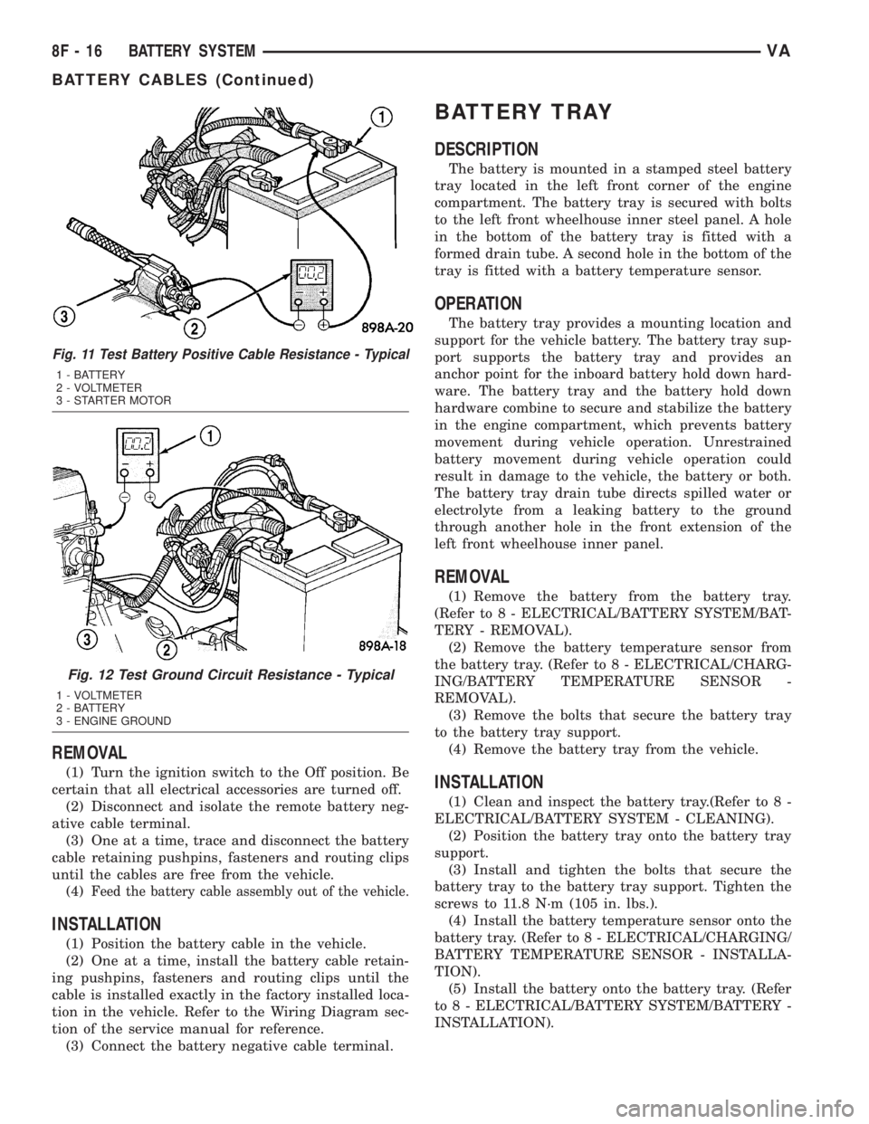
Fig. 11 Test Battery Positive Cable Resistance - Typical
1 - BATTERY
2 - VOLTMETER
3 - STARTER MOTOR
Fig. 12 Test Ground Circuit Resistance - Typical
1 - VOLTMETER
2 - BATTERY
3 - ENGINE GROUND
8F - 16 BATTERY SYSTEMVA
BATTERY CABLES (Continued)
Page 153 of 1232
Once the engine starts, the overrunning clutch pro-
tects the starter motor from damage by allowing the
starter pinion gear to spin faster than the pinion
shaft. When the driver releases the ignition switch to
the On position, the starter relay coil is de-energized.
This causes the relay contacts to open. When the
relay contacts open, the starter solenoid plunger
hold-in coil is de-energized.
When the solenoid plunger hold-in coil is de-ener-
gized, the solenoid plunger return spring returns the
plunger to its relaxed position. This causes the con-
tact disc to open the starter feed circuit, and the shiftlever to disengage the overrunning clutch and pinion
gear from the starter ring gear.
DIAGNOSIS AND TESTING - STARTING
SYSTEM
The battery, starting, and charging systems oper-
ate in conjunction with one another, and must be
tested as a complete system. For correct starting/
charging system operation, all of the components
involved in these 3 systems must perform within
specifications.
Starting System Diagnosis
CONDITION POSSIBLE CAUSE CORRECTION
STARTER FAILS TO
OPERATE.1. Battery discharged or
faulty.1. Refer to Battery. Charge or replace battery, if required.
2. Starting circuit wiring
faulty.2. Refer to 8, Wiring Diagrams. Test and repair starter
feed and/or control circuits, if required.
3. Starter relay faulty. 3. Refer to Starter Relay in Diagnosis and Testing.
Replace starter relay if required.
4. Ignition switch faulty. 4. Refer to Ignition Switch and Key Lock Cylinder.
Replace ignition switch if required.
5. Clutch pedal position
switch faulty.5. Refer to Clutch Pedal Position Switch.
6. Park/Neutral position
switch faulty or
misadjusted.6. Refer to Park/Neutral Position Switch. Replace
park/neutral position switch if required.
7. Starter solenoid faulty. 7. Refer to Starter Motor. Replace starter motor assembly
if required.
8. Starter motor faulty. 8. If all other starting system components and circuits test
OK, replace starter motor.
STARTER ENGAGES,
FAILS TO TURN
ENGINE.1. Battery discharged or
faulty.1. Refer to Battery. Charge or replace battery if required.
2. Starting circuit wiring
faulty.2. Refer to 8, Wiring Diagrams. Test and repair starter
feed and/or control circuits if required.
3. Starter motor faulty. 3. If all other starting system components and circuits test
OK, replace starter motor assembly.
4. Engine seized. 4. Refer to Engine Diagnosis in the Diagnosis and Testing
section of 9, Engine.
STARTER ENGAGES,
SPINS OUT BEFORE
ENGINE STARTS.1. Starter ring gear faulty. 1. Refer to Starter Motor Removal and Installation.
Remove starter motor to inspect starter ring gear.
Replace starter ring gear if required.
2. Starter motor faulty. 2. If all other starting system components and circuits test
OK, replace starter motor assembly.
VASTARTING SYSTEM 8F - 25
STARTING SYSTEM (Continued)
Page 154 of 1232
Starting System Diagnosis
CONDITION POSSIBLE CAUSE CORRECTION
STARTER DOES NOT
DISENGAGE.1. Starter motor
improperly installed.1. Refer to Starter Motor Removal and Installation.
Tighten starter mounting hardware to correct torque
specifications.
2. Starter relay faulty. 2. Refer to Starter Relay Diagnosis and Testing. Replace
starter relay if required.
3. Ignition switch faulty. 3. Refer to Ignition Switch and Key Lock Cylinder.
Replace ignition switch if required.
4. Starter motor faulty. 4. If all other starting system components and circuits test
OK, replace starter motor.
INSPECTION
For complete starter wiring circuit diagrams, refer
to 8, Wiring Diagrams. Before removing any unit
from starting system for repair or diagnosis, perform
the following inspections:
WARNING: ON VEHICLES EQUIPPED WITH AIR-
BAGS, REFER TO 8, PASSIVE RESTRAINT SYS-
TEMS, BEFORE ATTEMPTING ANY STEERING
WHEEL, STEERING COLUMN, OR INSTRUMENT
PANEL COMPONENT DIAGNOSIS OR SERVICE.
FAILURE TO TAKE THE PROPER PRECAUTIONS
COULD RESULT IN ACCIDENTAL AIRBAG DEPLOY-
MENT AND POSSIBLE PERSONAL INJURY.
²Battery- Visually inspect battery for indica-
tions of physical damage and loose or corroded cable
connections. Determine state-of-charge and cranking
capacity of battery. Charge or replace battery if
required. Refer toBatteryin 8, Battery.
²Ignition Switch- Visually inspect ignition
switch for indications of physical damage and loose
or corroded wire harness connections. Refer toIgni-
tion Switch and Key Lock Cylinder.
²Park/Neutral Position Switch- Visually
inspect park/neutral position switch for indications of
physical damage and loose or corroded wire harness
connections. Refer toPark/Neutral Position
Switchin 21, Transmission.
²Starter Relay- Visually inspect starter relay
for indications of physical damage and loose or cor-
roded wire harness connections.
²Starter Motor- Visually inspect starter motor
for indications of physical damage and loose or cor-
roded wire harness connections.
²Starter Solenoid- Visually inspect starter sole-
noid for indications of physical damage and loose or
corroded wire harness connections.
²Wiring- Visually inspect wire harnesses for
damage or corrosion. Repair or replace any faulty
wiring, as required. Refer to 8, Wiring Diagrams.
TESTING
COLD CRANKING TEST
For complete starter wiring circuit diagrams, refer
to 8, Wiring Diagrams. The battery must be fully-
charged and load-tested before proceeding. Refer to
Batteryin 8, Battery.
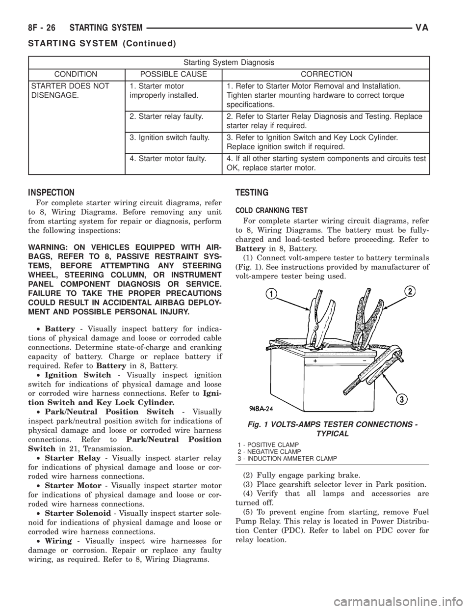
(1) Connect volt-ampere tester to battery terminals
(Fig. 1). See instructions provided by manufacturer of
volt-ampere tester being used.
(2) Fully engage parking brake.
(3) Place gearshift selector lever in Park position.
(4) Verify that all lamps and accessories are
turned off.
(5) To prevent engine from starting, remove Fuel
Pump Relay. This relay is located in Power Distribu-
tion Center (PDC). Refer to label on PDC cover for
relay location.
Fig. 1 VOLTS-AMPS TESTER CONNECTIONS -
TYPICAL
1 - POSITIVE CLAMP
2 - NEGATIVE CLAMP
3 - INDUCTION AMMETER CLAMP
8F - 26 STARTING SYSTEMVA
STARTING SYSTEM (Continued)
Page 155 of 1232
WARNING: IF EQUIPPED WITH DIESEL ENGINE,
ATTEMPT TO START ENGINE A FEW TIMES
BEFORE PROCEEDING WITH FOLLOWING STEP.
(6) Rotate and hold ignition switch in Start posi-
tion. Note cranking voltage and current (amperage)
draw readings shown on volt-ampere tester.
(a) If voltage reads below 9.6 volts, refer to
Starter Motorin Diagnosis and Testing. If starter
motor is OK, refer toEngine Diagnosisin 9,
Engine for further testing of engine. If starter
motor is not OK, replace faulty starter motor.
(b) If voltage reads above 9.6 volts and current
(amperage) draw reads below specifications, refer
toFeed Circuit Testin this section.
(c) If voltage reads 12.5 volts or greater and
starter motor does not turn, refer toControl Cir-
cuit Testingin this section.
(d) If voltage reads 12.5 volts or greater and
starter motor turns very slowly, refer toFeed Cir-
cuit Testin this section.
NOTE: A cold engine will increase starter current
(amperage) draw reading, and reduce battery volt-
age reading.
FEED CIRCUIT TEST
The starter feed circuit test (voltage drop method)
will determine if there is excessive resistance in
high-amperage feed circuit. For complete starter wir-
ing circuit diagrams, refer 8, Wiring Diagrams.
When performing these tests, it is important to
remember that voltage drop is giving an indication of
resistance between two points at which voltmeter
probes are attached.
Example:When testing resistance of positive bat-
tery cable, touch voltmeter leads to positive battery
cable clamp and cable connector at starter solenoid.
If you probe positive battery terminal post and cable
connector at starter solenoid, you are reading com-
bined voltage drop in positive battery cable clamp-to-
terminal post connection and positive battery cable.
The following operation will require a voltmeter
accurate to 1/10 (0.10) volt. Before performing tests,
be certain that following procedures are accom-
plished:
²Battery is fully-charged and load-tested. Refer to
Batteryin 8, Battery.
²Fully engage parking brake.
²Place gearshift selector lever in Park position.
²Verify that all lamps and accessories are turned
off.
²To prevent engine from starting, remove Fuel
Pump Relay. This relay is located in Power Distribu-
tion Center (PDC). Refer to label on PDC cover for
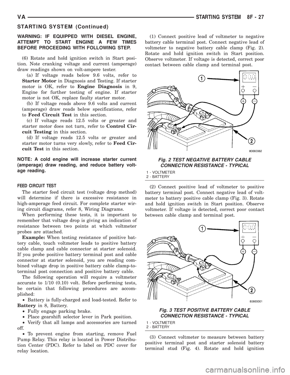
relay location.(1) Connect positive lead of voltmeter to negative
battery cable terminal post. Connect negative lead of
voltmeter to negative battery cable clamp (Fig. 2).
Rotate and hold ignition switch in Start position.
Observe voltmeter. If voltage is detected, correct poor
contact between cable clamp and terminal post.
(2) Connect positive lead of voltmeter to positive
battery terminal post. Connect negative lead of volt-
meter to battery positive cable clamp (Fig. 3). Rotate
and hold ignition switch in Start position. Observe
voltmeter. If voltage is detected, correct poor contact
between cable clamp and terminal post.
(3) Connect voltmeter to measure between battery
positive terminal post and starter solenoid battery
terminal stud (Fig. 4). Rotate and hold ignition
Fig. 2 TEST NEGATIVE BATTERY CABLE
CONNECTION RESISTANCE - TYPICAL
1 - VOLTMETER
2 - BATTERY
Fig. 3 TEST POSITIVE BATTERY CABLE
CONNECTION RESISTANCE - TYPICAL
1 - VOLTMETER
2 - BATTERY
VASTARTING SYSTEM 8F - 27
STARTING SYSTEM (Continued)
Page 156 of 1232
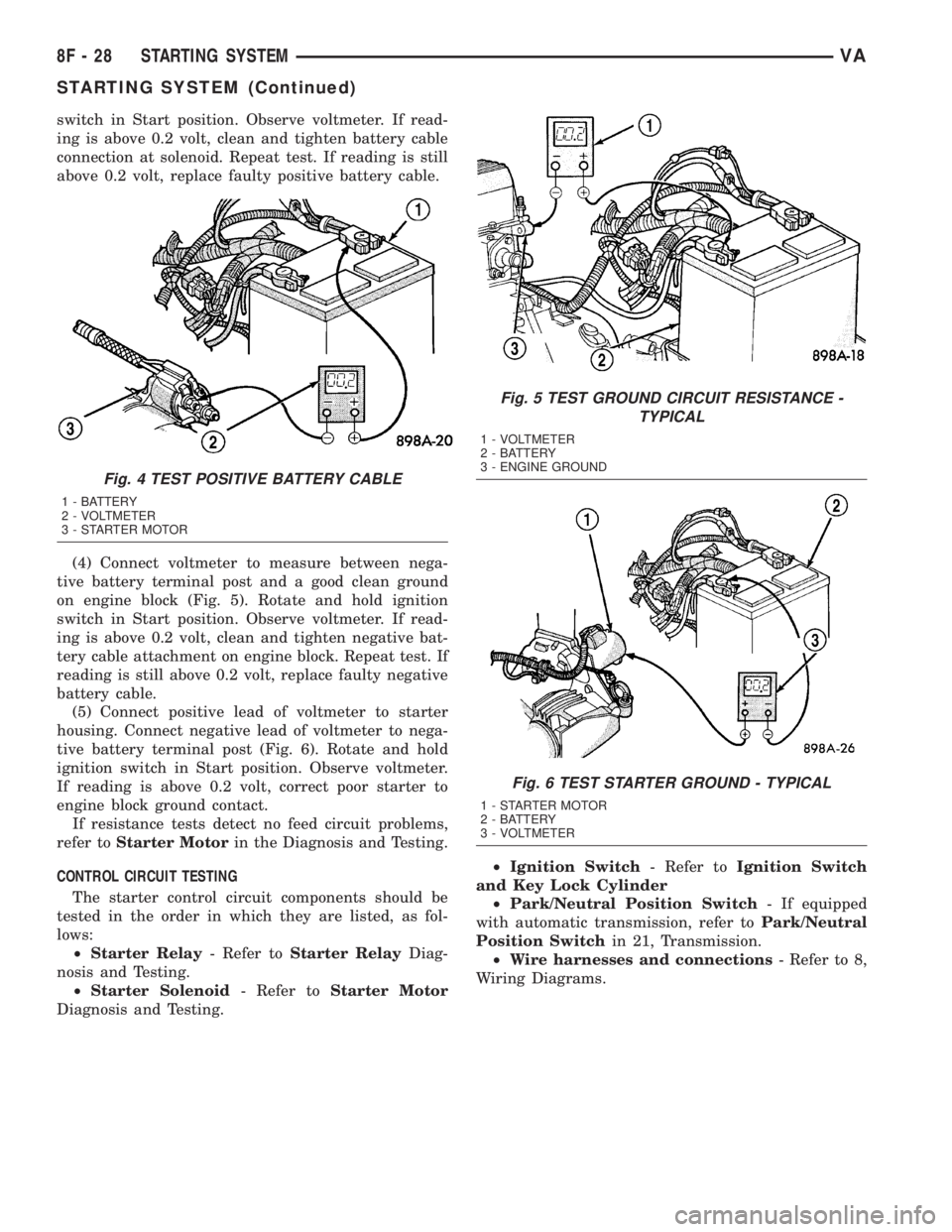
switch in Start position. Observe voltmeter. If read-
ing is above 0.2 volt, clean and tighten battery cable
connection at solenoid. Repeat test. If reading is still
above 0.2 volt, replace faulty positive battery cable.
(4) Connect voltmeter to measure between nega-
tive battery terminal post and a good clean ground
on engine block (Fig. 5). Rotate and hold ignition
switch in Start position. Observe voltmeter. If read-
ing is above 0.2 volt, clean and tighten negative bat-
tery cable attachment on engine block. Repeat test. If
reading is still above 0.2 volt, replace faulty negative
battery cable.
(5) Connect positive lead of voltmeter to starter
housing. Connect negative lead of voltmeter to nega-
tive battery terminal post (Fig. 6). Rotate and hold
ignition switch in Start position. Observe voltmeter.
If reading is above 0.2 volt, correct poor starter to
engine block ground contact.
If resistance tests detect no feed circuit problems,
refer toStarter Motorin the Diagnosis and Testing.
CONTROL CIRCUIT TESTING
The starter control circuit components should be
tested in the order in which they are listed, as fol-
lows:
²Starter Relay- Refer toStarter RelayDiag-
nosis and Testing.
²Starter Solenoid- Refer toStarter Motor
Diagnosis and Testing.²Ignition Switch- Refer toIgnition Switch
and Key Lock Cylinder
²Park/Neutral Position Switch- If equipped
with automatic transmission, refer toPark/Neutral
Position Switchin 21, Transmission.
²Wire harnesses and connections- Refer to 8,
Wiring Diagrams.
Fig. 4 TEST POSITIVE BATTERY CABLE
1 - BATTERY
2 - VOLTMETER
3 - STARTER MOTOR
Fig. 5 TEST GROUND CIRCUIT RESISTANCE -
TYPICAL
1 - VOLTMETER
2 - BATTERY
3 - ENGINE GROUND
Fig. 6 TEST STARTER GROUND - TYPICAL
1 - STARTER MOTOR
2 - BATTERY
3 - VOLTMETER
8F - 28 STARTING SYSTEMVA
STARTING SYSTEM (Continued)
Page 161 of 1232
HEATED SYSTEMS
TABLE OF CONTENTS
page page
HEATED SEATS
DESCRIPTION..........................1
OPERATION............................2
DIAGNOSIS AND TESTING - HEATED SEATS . . 2
DRIVER HEATED SEAT SWITCH
DESCRIPTION..........................2
OPERATION............................2
DIAGNOSIS AND TESTING - DRIVER HEATED
SEAT SWITCH.........................2
REMOVAL.............................3
INSTALLATION..........................3
HEATED SEAT ELEMENT
DESCRIPTION..........................3
OPERATION............................3
DIAGNOSIS AND TESTING - HEATED SEAT
ELEMENT............................3
HEATED SEAT RELAY
DESCRIPTION..........................4OPERATION............................4
DIAGNOSIS AND TESTING - HEATED SEAT
RELAY...............................4
REMOVAL.............................4
INSTALLATION..........................4
HEATED SEAT SENSOR
DESCRIPTION..........................4
DIAGNOSIS AND TESTING - HEATED SEAT
SENSOR.............................4
PASSENGER HEATED SEAT SWITCH
DESCRIPTION..........................5
OPERATION............................5
DIAGNOSIS AND TESTING - PASSENGER
HEATED SEAT SWITCH.................5
REMOVAL.............................5
INSTALLATION..........................5
HEATED SEATS
DESCRIPTION
Individually controlled, electrically heated front
seats are available factory-installed optional equip-
ment on this model. Vehicles with this option can be
visually identified by the two separate heated seat
switches mounted in the instrument panel. The
heated seat system allows the front seat driver and
passenger to select from two different levels of sup-
plemental electrical seat heating, or no seat heating
to suit their individual comfort requirements. The
heated seat system for this vehicle includes the fol-
lowing major components, which are described in fur-
ther detail later in this section:
²Heated Seat Elements- Four heated seat ele-
ments are used per vehicle, two for each front seat.
One heating element in the seat back and one in the
seat cushion. The heated seat sensor is integral to
the seat cushion heating element. The heated seat
elements are integral to the front seat and seat back
cushions. Refer to heated seat elements later in this
section for additional information.²Heated Seat Relay- One heated seat relay is
used per vehicle. The relay is located in the fuse
block and is responsible for distributing the voltage
(B+) to the heated seat elements.
²Heated Seat Sensors- Two heated seat sen-
sors are used per vehicle, one for each front seat. The
heated seat sensors are integral to each of the heated
seat element assemblies. Refer to heated seat sensor
later in this section for additional information.
²Heated Seat Switches- Two heated seat
switches are used per vehicle, one for each front seat.
The switches are mounted in the instrument panel.
Refer to heated seat switches later in this section for
additional information.
Hard wired circuitry connects the heated seat sys-
tem components to each other through the electrical
system of the vehicle. Refer to Wiring for additional
information. The wiring information includes wiring
diagrams, proper wire and connector repair proce-
dures, further details on wire harness routing and
retention, as well as pin-out and location views for
the various wire harness connectors, splices and
grounds.
VAHEATED SYSTEMS 8G - 1
Page 162 of 1232
OPERATION
The heated seat system is designed to provide indi-
vidually controlled, supplemental heat to the seat
cushion and seat back surfaces of both front seats.
Because this system converts electrical current to
heat, the heated seat system can provide a measure
of warm comfort almost immediately upon entering a
cold vehicle, rather than having to wait for the
engine coolant to reach sufficient temperature to
deliver heat through the conventional heater system.
This system allows each front seat occupant to indi-
vidually select one of two comfort levels, Hi or Lo, or
to turn the heater for their seat off.
The heated seat system components operate on
battery current received through a fuse in the Fuse
Block on a fused ignition switch output (run-acc) cir-
cuit so that the system will only operate when theignition switch is in the On or Accessory positions.
The heated seat system will be turned Off automati-
cally whenever the ignition switch is turned to any
position except On or Accessory. Also, the heated seat
system will not operate when the surface tempera-
ture of the seat cushion cover at either heated seat
sensor is above the designed temperature set points
of the system.
DIAGNOSIS AND TESTING - HEATED SEATS
Refer toWiringfor the appropriate wiring infor-
mation. The wiring information includes wiring dia-
grams, proper wire and connector repair procedures,
further details on wire harness routing and reten-
tion, as well as pin-out and location views for the
various wire harness connectors, splices and grounds.
HEATED SEAT SYSTEM DIAGNOSIS
CONDITION POSSIBLE CAUSES CORRECTION
NO HEATED SEAT SWITCH
ILLUMINATION WITH
IGNITION ON1. Faulty fuse. 1. Check heated seat fuse in Fuse Block.
Replace fuse, if required.
2. Wiring faulty. 2. Check fused ignition switch output (run-acc)
circuit from heated seat switch connector to
ignition switch. Repair, if required.
3. Ground faulty. 3. Check for ground at heated seat switch
connector. Repair, if required.
4. Faulty switch. 4. Refer to Heated Seat Switch for the proper
switch diagnosis and testing procedures.
DRIVER HEATED SEAT
SWITCH
DESCRIPTION
The heated seat switches are located on the instru-
ment panel, in the accessory switch bezel. The two,
momentary rocker type switches provide a signal to
the Heated Seat Relay through separate hard wired
circuits. Each switch contains two light emitting
diodes (LED), one for each High and Low setting to
let the occupant know that the seat heater system is
on.
The heated seat switches and their LED's cannot
be repaired. If either switch is faulty or damaged the
entire switch must be replaced.
OPERATION
There are three modes that can be selected with
each of the heated seat switches: Off, Low, and High.
When the top of the switch rocker is depressed, the
low mode is selected and the low mode LED indicator
illuminates. Depressing the top of the switch rocker asecond time will turn the heated seat to Off. This
same process is repeated for High heat setting. The
heated seats will automatically return to the Off
mode anytime the vehicle ignition switch is turned
Off.
Both switches provide separate hard wire inputs to
the Heated Seat Relay to indicate the selected mode.
The Heated Seat Relay responds to the heated seat
switch messages by controlling the output to the seat
heater elements of the selected seat.
DIAGNOSIS AND TESTING - DRIVER HEATED
SEAT SWITCH
For circuit description and diagrams, refer toWir-
ing.
(1) Inspect the Heated Seat Switches for apparent
damage or sticking/binding and replace if required.
Refer to Heated Seat Switch Removal and Installa-
tion in this section.
(2) Replace the heated seat switch with a known
good unit and retest the heated seat system.
8G - 2 HEATED SYSTEMSVA
HEATED SEATS (Continued)