2005 MERCEDES-BENZ SPRINTER glove box
[x] Cancel search: glove boxPage 194 of 1232
OPERATION
The tachometer gives an indication to the vehicle oper-
ator of the engine speed. This gauge is controlled by the
instrument cluster circuit board based upon cluster pro-
gramming and electronic messages received by the clus-
ter from the Engine Control Module (ECM) over the
Controller Area Network (CAN) data bus. The tachome-
ter is an air core magnetic unit that receives battery cur-
rent on the instrument cluster electronic circuit board
when the instrument cluster detects that the ignition
switch is in the On position. The cluster is programmed
to move the gauge needle back to the low end of the
scale after the ignition switch is turned to the Off posi-
tion. The instrument cluster circuitry controls the gauge
needle position and provides the following features:
²Engine Speed Message- Each time the cluster
receives an engine speed message from the ECM it
will calculate the correct engine speed reading and
position the gauge needle at that relative speed posi-
tion on the gauge scale. The gauge needle will con-
tinually be repositioned at the relative engine speed
position on the gauge scale until the engine stops
running, or until the ignition switch is turned to the
Off position, whichever occurs first.
²Communication Error- If the cluster fails to
receive an engine speed message, it will hold the
gauge needle at the last indication for about three
seconds, or until the ignition switch is turned to the
Off position, whichever occurs first. After three sec-
onds, the gauge needle will return to the left end of
the gauge scale.
The ECM continually monitors the crankshaft position
sensor to determine the engine speed. The ECM then
sends the proper engine speed messages to the instru-
ment cluster. For proper diagnosis of the crankshaft posi-
tion sensor, the ECM, the CAN data bus, or the
electronic message inputs to the instrument cluster that
control the tachometer, a DRBIIItscan tool is required.
Refer to the appropriate diagnostic information.
TRACTION CONTROL
INDICATOR
DESCRIPTION
A traction control (ASR) indicator is standard equip-
ment on all instrument clusters. The traction control
indicator is located near the center of the speedometer
in the instrument cluster. The traction control indicator
consists of an ª!º (exclamation point) imprinted within a
triangular cutout in the opaque layer of the instrument
cluster overlay. The dark outer layer of the overlay pre-
vents the indicator from being clearly visible when it is
not illuminated. An amber Light Emitting Diode (LED)
behind the cutout in the opaque layer of the overlay
causes the exclamation point to appear silhouettedagainst an amber field through the translucent outer
layer of the overlay when the indicator is illuminated
from behind by the LED, which is soldered onto the
instrument cluster electronic circuit board. The traction
control indicator is serviced as a unit with the instru-
ment cluster.
OPERATION
The traction control (ASR) indicator gives several
indications to the vehicle operator concerning the
operating status of the traction control (ASR) system.
The traction control indicator is controlled by a tran-
sistor on the instrument cluster circuit board based
upon cluster programming and electronic messages
received by the cluster from the Controller Anti-lock
Brake (CAB) over the Controller Area Network
(CAN) data bus. The traction control indicator Light
Emitting Diode (LED) is completely controlled by the
instrument cluster logic circuit, and that logic will
only allow this indicator to operate when the instru-
ment cluster detects that the ignition switch is in the
On position. Therefore, the LED will always be off
when the ignition switch is in any position except
On. The LED only illuminates when it is provided a
path to ground by the instrument cluster transistor.
The instrument cluster will turn on the traction con-
trol indicator for the following reasons:
²Bulb Test-
Each time the ignition switch is
turned to the On position the traction control indicator
is illuminated for about two seconds as a bulb test.
²Traction Control (ASR) Indicator Lamp-On
Message-
Each time the cluster receives a traction
control indicator lamp-on message from the CAB, the
indicator will be illuminated. This indicator can be
flashed on and off, or illuminated solid, as dictated by
the CAB message. The indicator is illuminated solid
when the traction control system has been deactivated;
and is flashed when the traction control is activated or
when the driven wheels lose traction with the traction
control deactivated. The indicator remains flashing or
illuminated solid until the cluster receives a lamp-off
message from the CAB, or until the ignition switch is
turned to the Off position, whichever occurs first.
The CAB continually monitors the traction control
(ASR) switch and the four wheel speed sensors to deter-
mine the correct operating mode for the traction control
system. The CAB then sends the proper lamp-on or lamp-
off messages to the instrument cluster. See the owner's
manual in the vehicle glove box for more information on
the features, use, activation and deactivation of the trac-
tion control (ASR) system. For proper diagnosis of the
traction control system, the CAB, the CAN data bus, or
the electronic message inputs to the instrument cluster
that control the traction control indicator, a DRBIIIt
scan tool is required. Refer to the appropriate diagnostic
information.
8J - 24 INSTRUMENT CLUSTERVA
TACHOMETER (Continued)
Page 195 of 1232
TRACTION CONTROL
MALFUNCTION INDICATOR
DESCRIPTION
A traction control (ASR) malfunction indicator is
standard equipment on all instrument clusters. The
traction control malfunction indicator is located near
the lower edge of the instrument cluster, to the right
of the multi-function indicator display. The traction
control malfunction indicator consists of an icon that
graphically depicts a tire and two skid marks
imprinted within a rectangular cutout in the opaque
layer of the instrument cluster overlay. The dark
outer layer of the overlay prevents the indicator from
being clearly visible when it is not illuminated. An
amber Light Emitting Diode (LED) behind the cutout
in the opaque layer of the overlay causes the icon to
appear silhouetted against an amber field through
the translucent outer layer of the overlay when the
indicator is illuminated from behind by the LED,
which is soldered onto the instrument cluster elec-
tronic circuit board. The traction control malfunction
indicator is serviced as a unit with the instrument
cluster.
OPERATION
The traction control (ASR) malfunction indicator
gives the vehicle operator an indication when the
traction control system is faulty or inoperative. This
indicator is controlled by a transistor on the instru-
ment cluster circuit board based upon cluster pro-
gramming and electronic messages received by the
cluster from the Controller Antilock Brake (CAB)
over the Controller Area Network (CAN) data bus.
The traction control malfunction indicator Light
Emitting Diode (LED) is completely controlled by the
instrument cluster logic circuit, and that logic will
only allow this indicator to operate when the instru-
ment cluster detects that the ignition switch is in the
On position. Therefore, the LED will always be off
when the ignition switch is in any position except
On. The LED only illuminates when it is provided a
path to ground by the instrument cluster transistor.
The instrument cluster will turn on the traction con-
trol malfunction indicator for the following reasons:
²Bulb Test- Each time the ignition switch is
turned to the On position the traction control indica-
tor is illuminated as a bulb test until the engine is
started.
²Traction Control (ASR) Malfunction Indica-
tor Lamp-On Message- Each time the cluster
receives a traction control malfunction indicator
lamp-on message from the CAB, the indicator will be
illuminated. The indicator remains illuminated until
the cluster receives a lamp-off message from theCAB, or until the ignition switch is turned to the Off
position, whichever occurs first.
The CAB continually monitors the traction control
(ASR) system circuits and sensors to decide whether
the system is in good operating condition. The CAB
then sends the proper lamp-on or lamp-off messages
to the instrument cluster. If the CAB sends a
lamp-on message after the bulb test, it indicates that
the CAB has detected a system malfunction and that
the traction control (ASR) system has become inoper-
ative. The CAB will store a Diagnostic Trouble Code
(DTC) for any malfunction it detects. In addition, if
the traction control malfunction indicator is illumi-
nated, the CAB will deactivate an activated traction
control system and engine power output may be
reduced. See the owner's manual in the vehicle glove
box for more information on the features, use, activa-
tion and deactivation of the traction control (ASR)
system. For proper diagnosis of the traction control
system, the CAB, the CAN data bus, or the electronic
message inputs to the instrument cluster that control
the traction control malfunction indicator, a DRBIIIt
scan tool is required. Refer to the appropriate diag-
nostic information.
TURN SIGNAL INDICATOR
DESCRIPTION
Two turn signal indicators, one right and one left,
are standard equipment on all instrument clusters.
The turn signal indicators are located near the upper
edge of the instrument cluster, one to each side of the
speedometer. Each turn signal indicator consists of a
arrow-shaped cutout of the International Control and
Display Symbol icon for ªTurn Warningº in the
opaque layer of the instrument cluster overlay. The
dark outer layer of the overlay prevents these icons
from being clearly visible when they are not illumi-
nated. A green Light Emitting Diode (LED) behind
each turn signal indicator cutout in the opaque layer
of the overlay causes the icon to appear in green
through the translucent outer layer of the overlay
when the indicator is illuminated from behind by the
LED, which is soldered onto the instrument cluster
electronic circuit board. The turn signal indicators
are serviced as a unit with the instrument cluster.
OPERATION
The turn signal indicators give an indication to the
vehicle operator that the turn signal (left or right
indicator flashing) or hazard warning (both left and
right indicators flashing) have been selected and are
operating. These indicators are controlled by transis-
tors on the instrument cluster electronic circuit board
based upon the cluster programming and a hard
VAINSTRUMENT CLUSTER 8J - 25
Page 241 of 1232
ACTIVE RESTRAINTS
The active restraints for this model include:
²Front Seat Belts- Both outboard front seating
positions are equipped with three-point seat belt sys-
tems employing a lower B-pillar mounted inertia
latch-type retractors, height-adjustable upper B-pil-
lar mounted turning loops, travelling lower seat belt
anchors secured to the outboard seat tracks, and
travelling end-release seat belt buckles secured to
the inboard seat track. The driver side front seat belt
buckle of all models includes an integral seat belt
switch that detects whether its seat belt has been
fastened.
²Rear Seat Belts- All rear seating positions are
equipped with three-point seat belt systems. Each
rear seating position belt employs an integral seat
cushion frame mounted inertia latch-type retractor, a
fixed position upper seat back frame mounted turn-
ing loop, and a fixed lower seat belt anchor secured
to the seat cushion frame. All rear seat belts have
fixed end-release seat belt buckles that are also
secured to the seat cushion frame.
PASSIVE RESTRAINTS
A Next Generation driver airbag is standard facto-
ry-installed safety equipment on this model, while a
passenger side front airbag is optional. This airbag
system is a passive, inflatable, Supplemental
Restraint System (SRS) and vehicles with this equip-
ment can be readily identified by the ªSRS - AIR-
BAGº logo molded into the driver airbag trim cover
in the center of the steering wheel and, if the vehicle
is so equipped, also into the passenger airbag door on
the instrument panel above the glove box (Fig. 2).
Vehicles with the airbag system can also be identified
by the airbag indicator, which will illuminate in the
instrument cluster for about six seconds as a bulb
test each time the ignition switch is turned to the On
position. A pyrotechnic-type seat belt tensioner is
integral to the front seat belt retractor mounted on
the lower B-pillar on the driver side, and to the pas-
senger side retractor of vehicles equipped with the
optional passenger side airbag.
The supplemental restraint system includes the
following major components, which are described in
further detail elsewhere in this service information:
²Airbag Control Module- The Airbag Control
Module (ACM) is located on a mount on the floor
panel within the driver side seat riser, beneath the
driver seat in the passenger compartment.
²Airbag (SRS) Indicator- The airbag indicator
is integral to the ElectroMechanical Instrument Clus-
ter (EMIC), which is located on the instrument panel
in front of the driver.²Clockspring- The clockspring is located near
the top of the steering column, directly beneath the
steering wheel.
²Driver Airbag- The driver airbag is located in
the center of the steering wheel, beneath the driver
airbag trim cover.
²Driver Knee Blocker- The structure of the
lower instrument panel serves as a knee blocker for
the driver.
²Passenger Airbag- The optional passenger air-
bag is located within the instrument panel, behind
the passenger airbag door on the instrument panel
above the glove box on the passenger side of the vehi-
cle.
²Passenger Knee Blocker- The structure of
the glove box door and the lower instrument panel
serve as a knee blocker for the front seat passenger.
²Seat Belt Tensioner- A seat belt tensioner is
integral to the driver side front seat belt retractor
unit, and to the passenger side front seat belt retrac-
tor unit on vehicles equipped with an optional pas-
senger airbag.
The ACM contains a central processing unit and
programming that allows it to communicate on a
serial data bus diagnostic circuit connected to the
16-way Data Link Connector (DLC) located below the
left end of the instrument panel. This method of com-
munication is used for initialization of the ACM and
for diagnosis of the SRS circuits and components
using a DRBIIItscan tool.
Hard wired circuitry connects the supplemental
restraint system components to each other through
the electrical system of the vehicle. These hard wired
circuits are integral to several wire harnesses, which
are routed throughout the vehicle and retained by
many different methods. These circuits may be con-
nected to each other, to the vehicle electrical system,
and to the supplemental restraint system compo-
nents through the use of a combination of soldered
Fig. 2 SRS Logo
VARESTRAINTS 8O - 3
RESTRAINTS (Continued)
Page 242 of 1232
splices, splice block connectors, and many different
types of wire harness terminal connectors and insu-
lators. Refer to the appropriate wiring information.
The wiring information includes wiring diagrams,
proper wire and connector repair procedures, further
details on wire harness routing and retention, as well
as pin-out and location views for the various wire
harness connectors, splices and grounds.
OPERATION
ACTIVE RESTRAINTS
The primary passenger restraints in this or any
other vehicle are the standard equipment factory-in-
stalled seat belts. Seat belts are referred to as an
active restraint because the vehicle occupants are
required to physically fasten and properly adjust
these restraints in order to benefit from them. See
the owner's manual in the vehicle glove box for more
information on the features, use and operation of all
of the factory-installed active restraints.
PASSIVE RESTRAINTS
The passive restraints are referred to as a supple-
mental restraint system because they were designed
and are intended to enhance the protection for the
occupants of the vehicleonlywhen used in conjunc-
tion with the seat belts. They are referred to as pas-
sive restraints because the vehicle occupants are not
required to do anything to make them operate; how-
ever, the vehicle occupants must be wearing their
seat belts in order to obtain the maximum safety
benefit from the factory-installed supplemental
restraint system.
The supplemental restraint system electrical cir-
cuits are continuously monitored and controlled by a
microprocessor and software contained within the
Airbag Control Module (ACM). An airbag indicator in
the ElectroMechanical Instrument Cluster (EMIC)
illuminates for about four seconds as a bulb test each
time the ignition switch is turned to the On or Start
positions. Following the bulb test, the airbag indica-
tor is turned on or off by the ACM to indicate the
status of the supplemental restraint system. If the
airbag indicator comes on either solid or flashing at
any time other than during the bulb test, it indicates
that there is a problem in the supplemental restraint
system electrical circuits. Such a problem may cause
airbags not to deploy when required, or to deploy
when not required.
Deployment of the supplemental restraints
depends upon the angle and severity of an impact.Deployment is not based upon vehicle speed; rather,
deployment is based upon the rate of deceleration as
measured by the forces of gravity (G force) upon the
impact sensor. When an impact is severe enough, the
microprocessor in the ACM signals the inflator of the
appropriate airbag units to deploy their airbag cush-
ions. The front seat belt tensioners are provided with
a deployment signal by the ACM in conjunction with
the driver and passenger airbags. During a frontal
vehicle impact, the knee blockers work in concert
with properly fastened and adjusted seat belts to
restrain both the driver and the front seat passenger
in the proper position for an airbag deployment. The
knee blockers also absorb and distribute the crash
energy from the driver and the front seat passenger
to the structure of the instrument panel. The seat
belt tensioners remove the slack from the front seat
belts to provide further assurance that the driver and
front seat passenger are properly positioned and
restrained for an airbag deployment.
Typically, the vehicle occupants recall more about
the events preceding and following a collision than
they do of an airbag deployment itself. This is
because the airbag deployment and deflation occur so
rapidly. In a typical 48 kilometer-per-hour (30 mile-
per-hour) barrier impact, from the moment of impact
until the airbags are fully inflated takes only a few
milliseconds. Within one to two seconds from the
moment of impact, the airbags are almost entirely
deflated. The times cited for these events are approx-
imations, which apply only to a barrier impact at the
given speed. Actual times will vary somewhat,
depending upon the vehicle speed, impact angle,
severity of the impact, and the type of collision.
When the ACM monitors a problem in any of the
front airbag system circuits or components, including
the seat belt tensioners, it stores a fault code or
Diagnostic Trouble Code (DTC) in its memory circuit
and sends a hard wired output to the EMIC to turn
on the airbag indicator. If the EMIC detects a prob-
lem in the airbag indicator or airbag indicator circuit,
the cluster will flash the seatbelt indicator on and
off. Proper testing of the supplemental restraint sys-
tem components as well as the retrieval or erasure of
a DTC from the ACM requires the use of a DRBIIIt
scan tool. Refer to the appropriate diagnostic infor-
mation.
See the owner's manual in the vehicle glove box for
more information on the features, use and operation
of all of the factory-installed passive restraints.
8O - 4 RESTRAINTSVA
RESTRAINTS (Continued)
Page 261 of 1232
INSTALLATION
WARNING: DURING AND FOLLOWING ANY SEAT
BELT SERVICE, CAREFULLY INSPECT ALL SEAT
BELTS, BUCKLES, MOUNTING HARDWARE,
RETRACTORS, AND ANCHORS FOR PROPER
INSTALLATION, OPERATION, OR DAMAGE.
REPLACE ANY BELT THAT IS CUT, FRAYED, OR
TORN. STRAIGHTEN ANY BELT THAT IS TWISTED.
TIGHTEN ANY LOOSE FASTENERS. REPLACE ANY
BELT THAT HAS A DAMAGED OR INOPERATIVE
BUCKLE OR RETRACTOR. REPLACE ANY BELT
THAT HAS A BENT OR DAMAGED LATCH PLATE
OR ANCHOR PLATE. NEVER ATTEMPT TO REPAIR
A SEAT BELT COMPONENT. ALWAYS REPLACE
DAMAGED OR FAULTY SEAT BELT COMPONENTS
WITH THE CORRECT, NEW AND UNUSED
REPLACEMENT PARTS LISTED IN THE
DAIMLERCHRYSLER MOPAR PARTS CATALOG.
(1) Position the front seat belt buckle to the
inboard side of the front seat frame (Fig. 26).
(2) Install and tighten the screw that secures the
front seat belt buckle lower anchor to the inboard
side of the front seat frame. Tighten the screw to 35
N´m (26 ft. lbs.).
(3) If the vehicle is so equipped, snap the plastic
cover over the screw that secures the front seat belt
buckle lower anchor to the inboard side of the seat
frame.
(4) On the driver side only, reconnect the seat belt
switch pigtail wire to the vehicle wire harness and
push the joined connectors through the clearance
hole in the seat riser cover.
(5) On the driver side only, route and secure the
seat belt switch pigtail wire to the seat frame with
wire ties.
PASSENGER AIRBAG
DESCRIPTION
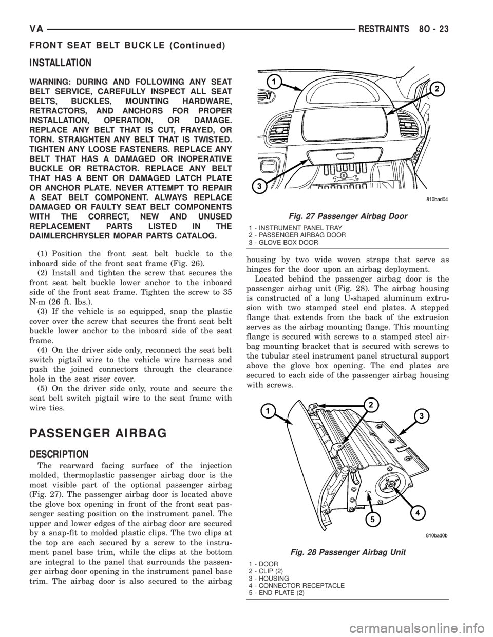
The rearward facing surface of the injection
molded, thermoplastic passenger airbag door is the
most visible part of the optional passenger airbag
(Fig. 27). The passenger airbag door is located above
the glove box opening in front of the front seat pas-
senger seating position on the instrument panel. The
upper and lower edges of the airbag door are secured
by a snap-fit to molded plastic clips. The two clips at
the top are each secured by a screw to the instru-
ment panel base trim, while the clips at the bottom
are integral to the panel that surrounds the passen-
ger airbag door opening in the instrument panel base
trim. The airbag door is also secured to the airbaghousing by two wide woven straps that serve as
hinges for the door upon an airbag deployment.
Located behind the passenger airbag door is the
passenger airbag unit (Fig. 28). The airbag housing
is constructed of a long U-shaped aluminum extru-
sion with two stamped steel end plates. A stepped
flange that extends from the back of the extrusion
serves as the airbag mounting flange. This mounting
flange is secured with screws to a stamped steel air-
bag mounting bracket that is secured with screws to
the tubular steel instrument panel structural support
above the glove box opening. The end plates are
secured to each side of the passenger airbag housing
with screws.
Fig. 27 Passenger Airbag Door
1 - INSTRUMENT PANEL TRAY
2 - PASSENGER AIRBAG DOOR
3 - GLOVE BOX DOOR
Fig. 28 Passenger Airbag Unit
1 - DOOR
2 - CLIP (2)
3 - HOUSING
4 - CONNECTOR RECEPTACLE
5 - END PLATE (2)
VARESTRAINTS 8O - 23
FRONT SEAT BELT BUCKLE (Continued)
Page 287 of 1232
and methods. Proper testing of the intermittent wipe
logic circuitry within the fuse block requires the use
of a DRBIIItscan tool. Refer to the appropriate diag-
nostic information. Refer to the owner's manual in
the vehicle glove box for more information on the fea-
tures and operation of the wiper and washer system.
DIAGNOSIS AND TESTING - WIPER &
WASHER SYSTEM
If the wiper motor operates, but the wipers do not
move on the windshield, replace the faulty wiper
linkage module. If the washer pump/motor operates,
but no washer fluid is dispensed on the glass; or, if
the wipers operate, but chatter, lift, or do not clear
the glass, clean and inspect the wiper and washer
system components as required. (Refer to 8 - ELEC-
TRICAL/WIPERS/WASHERS - CLEANING) and
(Refer to 8 - ELECTRICAL/WIPERS/WASHERS -
INSPECTION). For diagnosis and testing of the
multi-function switch (Refer to 8 - ELECTRICAL/
LAMPS/LIGHTING - EXTERIOR/MULTI-FUNC-
TION SWITCH - DIAGNOSIS AND TESTING).
Refer to the appropriate wiring information. The wir-
ing information includes wiring diagrams, proper
wire and connector repair procedures, details of wire
harness routing and retention, connector pin-out
information and location views for the various wire
harness connectors, splices and grounds.
The hard wired circuits and components of the
wiper and washer system may be diagnosed and
tested using conventional diagnostic tools and proce-
dures. However, conventional diagnostic methods
may not prove conclusive in the diagnosis of the
intermittent wipe logic circuitry contained within the
fuse block underneath the steering column. The most
reliable, efficient, and accurate means to diagnose
the intermittent wipe logic circuitry requires the use
of a DRBIIItscan tool. Refer to the appropriate diag-
nostic information.
WARNING: ON VEHICLES EQUIPPED WITH AIR-
BAGS, DISABLE THE SUPPLEMENTAL RESTRAINT
SYSTEM BEFORE ATTEMPTING ANY STEERING
WHEEL, STEERING COLUMN, DRIVER AIRBAG,
PASSENGER AIRBAG, SEAT BELT TENSIONER, OR
INSTRUMENT PANEL COMPONENT DIAGNOSIS OR
SERVICE. DISCONNECT AND ISOLATE THE BAT-
TERY NEGATIVE (GROUND) CABLE, THEN WAIT
TWO MINUTES FOR THE SYSTEM CAPACITOR TO
DISCHARGE BEFORE PERFORMING FURTHER
DIAGNOSIS OR SERVICE. THIS IS THE ONLY SURE
WAY TO DISABLE THE SUPPLEMENTAL
RESTRAINT SYSTEM. FAILURE TO TAKE THE
PROPER PRECAUTIONS COULD RESULT IN ACCI-
DENTAL AIRBAG DEPLOYMENT AND POSSIBLE
PERSONAL INJURY.
CLEANING - WIPER & WASHER SYSTEM
WIPER SYSTEM
The squeegees of wiper blades exposed to the ele-
ments for a long time tend to lose their wiping effec-
tiveness. Periodic cleaning of the squeegees is
suggested to remove any deposits of salt or road film.
The wiper blades, arms, and windshield glass should
only be cleaned using a sponge or soft cloth and
windshield washer fluid, a mild detergent, or a non-
abrasive cleaner. If the wiper blades continue to
leave streaks, smears, hazing, or beading on the
glass after thorough cleaning of the squeegees and
the glass, the entire wiper blade assembly must be
replaced.
CAUTION: Protect the rubber squeegees of the
wiper blades from any petroleum-based cleaners,
solvents, or contaminants. These products can rap-
idly deteriorate the rubber squeegees.
WASHER SYSTEM
If the washer system is contaminated with foreign
material, drain the washer reservoir by removing the
washer pump/motor from the reservoir. Clean foreign
material from the inside of the washer pump/motor
inlet nipple and the washer reservoir using clean
washer fluid, a mild detergent, or a non-abrasive
cleaner. Flush foreign material from the washer sys-
tem plumbing by first disconnecting the washer
hoses from the washer nozzles, then running the
washer pump/motor to run clean washer fluid or
water through the system. Plugged or restricted
washer nozzles should be carefully back-flushed
using compressed air. If the washer nozzle obstruc-
tion cannot be cleared, replace the washer nozzle.
CAUTION: Never introduce petroleum-based clean-
ers, solvents, or contaminants into the washer sys-
tem. These products can rapidly deteriorate the
rubber seals and hoses of the washer system, as
well as the rubber squeegees of the wiper blades.
CAUTION: Never use compressed air to flush the
washer system plumbing. Compressed air pres-
sures are too great for the washer system plumbing
components and will result in further system dam-
age. Never use sharp instruments to clear a
plugged washer nozzle or damage to the nozzle ori-
fice and improper nozzle spray patterns will result.
VAWIPERS/WASHERS 8R - 5
WIPERS/WASHERS (Continued)
Page 1091 of 1232
INSTRUMENT PANEL
TABLE OF CONTENTS
page page
CLUSTER BEZEL
REMOVAL.............................53
INSTALLATION.........................54
ACCESSORY SWITCH BEZEL
REMOVAL.............................54
INSTALLATION.........................54
INSTRUMENT PANEL CENTER BEZEL
REMOVAL.............................55
INSTALLATION.........................55
ASH RECEIVER
REMOVAL.............................55
INSTALLATION.........................55
CUP HOLDER
REMOVAL.............................55
INSTALLATION.........................56
GLOVE BOX
REMOVAL.............................56INSTALLATION.........................56
INSTRUMENT PANEL ASSEMBLY
REMOVAL.............................57
INSTALLATION.........................61
TOP COVER - CLUSTER
REMOVAL.............................62
INSTALLATION.........................62
TOP COVER - TRAY
REMOVAL.............................63
INSTALLATION.........................64
TOP COVER
REMOVAL.............................64
INSTALLATION.........................65
STEERING COLUMN OPENING COVER
REMOVAL.............................66
INSTALLATION.........................66
CLUSTER BEZEL
REMOVAL
WARNING: ON VEHICLES EQUIPPED WITH AIR-
BAGS, DISABLE THE AIRBAG SYSTEM BEFORE
ATTEMPTING ANY STEERING WHEEL, STEERING
COLUMN, SEAT BELT TENSIONER, OR INSTRU-
MENT PANEL COMPONENT DIAGNOSIS OR SER-
VICE. DISCONNECT AND ISOLATE THE BATTERY
NEGATIVE (GROUND) CABLE, THEN WAIT TWO
MINUTES FOR THE AIRBAG SYSTEM CAPACITOR
TO DISCHARGE BEFORE PERFORMING FURTHER
DIAGNOSIS OR SERVICE. THIS IS THE ONLY SURE
WAY TO DISABLE THE AIRBAG SYSTEM. FAILURE
TO TAKE THE PROPER PRECAUTIONS COULD
RESULT IN ACCIDENTAL AIRBAG DEPLOYMENT
AND POSSIBLE PERSONAL INJURY.
(1) Disconnect and isolate the battery negative
cable.
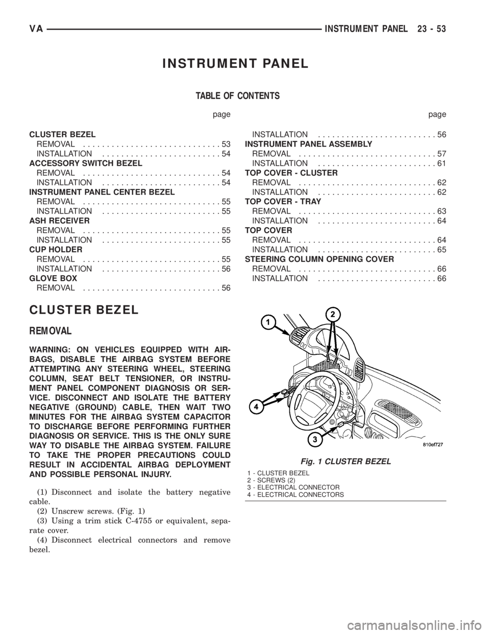
(2) Unscrew screws. (Fig. 1)
(3) Using a trim stick C-4755 or equivalent, sepa-
rate cover.
(4) Disconnect electrical connectors and remove
bezel.
Fig. 1 CLUSTER BEZEL
1 - CLUSTER BEZEL
2 - SCREWS (2)
3 - ELECTRICAL CONNECTOR
4 - ELECTRICAL CONNECTORS
VAINSTRUMENT PANEL 23 - 53
Page 1094 of 1232
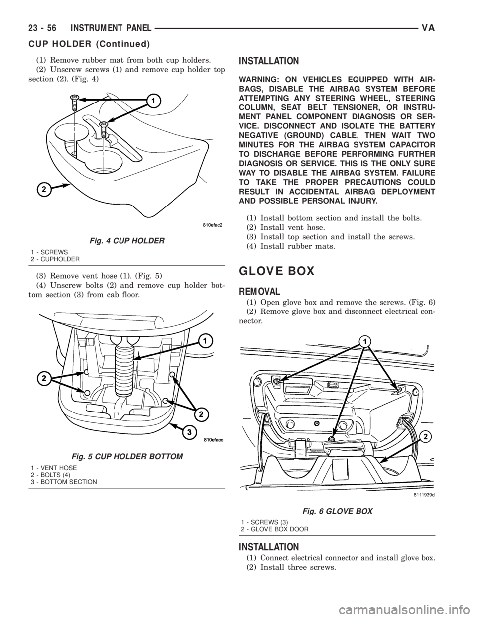
(1) Remove rubber mat from both cup holders.
(2) Unscrew screws (1) and remove cup holder top
section (2). (Fig. 4)
(3) Remove vent hose (1). (Fig. 5)
(4) Unscrew bolts (2) and remove cup holder bot-
tom section (3) from cab floor.INSTALLATION
WARNING: ON VEHICLES EQUIPPED WITH AIR-
BAGS, DISABLE THE AIRBAG SYSTEM BEFORE
ATTEMPTING ANY STEERING WHEEL, STEERING
COLUMN, SEAT BELT TENSIONER, OR INSTRU-
MENT PANEL COMPONENT DIAGNOSIS OR SER-
VICE. DISCONNECT AND ISOLATE THE BATTERY
NEGATIVE (GROUND) CABLE, THEN WAIT TWO
MINUTES FOR THE AIRBAG SYSTEM CAPACITOR
TO DISCHARGE BEFORE PERFORMING FURTHER
DIAGNOSIS OR SERVICE. THIS IS THE ONLY SURE
WAY TO DISABLE THE AIRBAG SYSTEM. FAILURE
TO TAKE THE PROPER PRECAUTIONS COULD
RESULT IN ACCIDENTAL AIRBAG DEPLOYMENT
AND POSSIBLE PERSONAL INJURY.
(1) Install bottom section and install the bolts.
(2) Install vent hose.
(3) Install top section and install the screws.
(4) Install rubber mats.
GLOVE BOX
REMOVAL
(1) Open glove box and remove the screws. (Fig. 6)
(2) Remove glove box and disconnect electrical con-
nector.
INSTALLATION
(1)Connect electrical connector and install glove box.
(2) Install three screws.
Fig. 4 CUP HOLDER
1 - SCREWS
2 - CUPHOLDER
Fig. 5 CUP HOLDER BOTTOM
1 - VENT HOSE
2 - BOLTS (4)
3 - BOTTOM SECTION
Fig. 6 GLOVE BOX
1 - SCREWS (3)
2 - GLOVE BOX DOOR
23 - 56 INSTRUMENT PANELVA
CUP HOLDER (Continued)