2005 MERCEDES-BENZ SPRINTER sliding
[x] Cancel search: slidingPage 1075 of 1232
INSIDE HANDLE ACTUATOR
REMOVAL
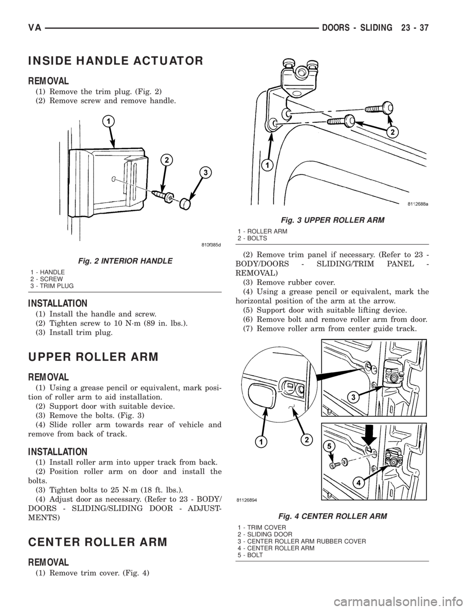
(1) Remove the trim plug. (Fig. 2)
(2) Remove screw and remove handle.
INSTALLATION
(1) Install the handle and screw.
(2) Tighten screw to 10 N´m (89 in. lbs.).
(3) Install trim plug.
UPPER ROLLER ARM
REMOVAL
(1) Using a grease pencil or equivalent, mark posi-
tion of roller arm to aid installation.
(2) Support door with suitable device.
(3) Remove the bolts. (Fig. 3)
(4) Slide roller arm towards rear of vehicle and
remove from back of track.
INSTALLATION
(1) Install roller arm into upper track from back.
(2) Position roller arm on door and install the
bolts.
(3) Tighten bolts to 25 N´m (18 ft. lbs.).
(4) Adjust door as necessary. (Refer to 23 - BODY/
DOORS - SLIDING/SLIDING DOOR - ADJUST-
MENTS)
CENTER ROLLER ARM
REMOVAL
(1) Remove trim cover. (Fig. 4)(2) Remove trim panel if necessary. (Refer to 23 -
BODY/DOORS - SLIDING/TRIM PANEL -
REMOVAL)
(3) Remove rubber cover.
(4) Using a grease pencil or equivalent, mark the
horizontal position of the arm at the arrow.
(5) Support door with suitable lifting device.
(6) Remove bolt and remove roller arm from door.
(7) Remove roller arm from center guide track.
Fig. 2 INTERIOR HANDLE
1 - HANDLE
2 - SCREW
3 - TRIM PLUG
Fig. 3 UPPER ROLLER ARM
1 - ROLLER ARM
2 - BOLTS
Fig. 4 CENTER ROLLER ARM
1 - TRIM COVER
2 - SLIDING DOOR
3 - CENTER ROLLER ARM RUBBER COVER
4 - CENTER ROLLER ARM
5 - BOLT
VADOORS - SLIDING 23 - 37
Page 1076 of 1232
INSTALLATION
(1) Position roller arm in guide track.
(2) Install arm into door opening and line up tab
with marks made previously.
(3) Install bolt and tighten to 45 N´m (33 ft. lbs.).
(4) Install rubber cover.
(5) Adjust door if necessary. (Refer to 23 - BODY/
DOORS - SLIDING/SLIDING DOOR - ADJUST-
MENTS)
(6) Install trim panel if necessary. (Refer to 23 -
BODY/DOORS - SLIDING/TRIM PANEL - INSTAL-
LATION)
(7) Install trim cover.
LOWER ROLLER ARM
REMOVAL
(1) Remove trim plugs and screws and remove
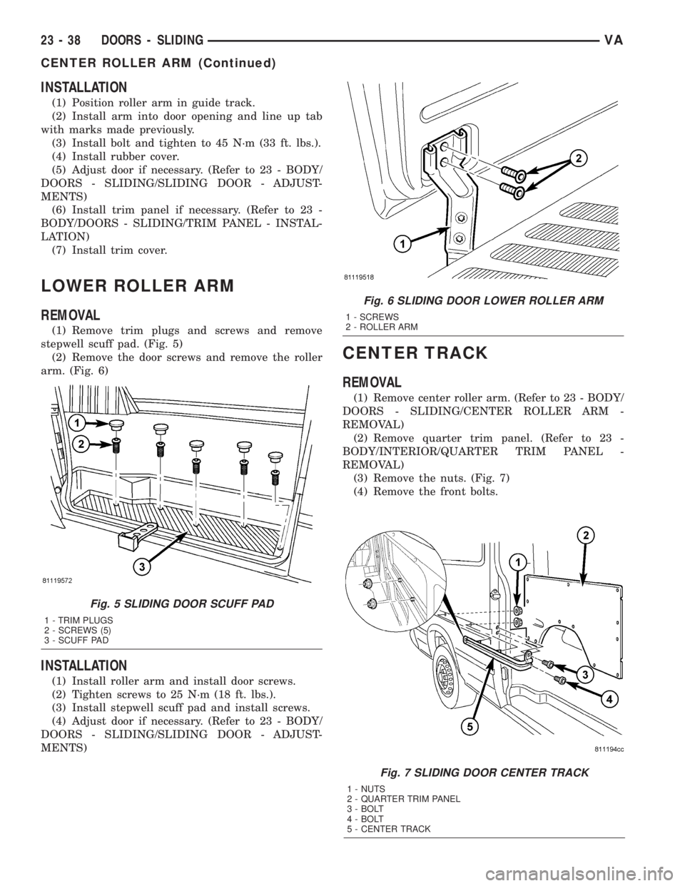
stepwell scuff pad. (Fig. 5)
(2) Remove the door screws and remove the roller
arm. (Fig. 6)
INSTALLATION
(1) Install roller arm and install door screws.
(2) Tighten screws to 25 N´m (18 ft. lbs.).
(3) Install stepwell scuff pad and install screws.
(4) Adjust door if necessary. (Refer to 23 - BODY/
DOORS - SLIDING/SLIDING DOOR - ADJUST-
MENTS)
CENTER TRACK
REMOVAL
(1) Remove center roller arm. (Refer to 23 - BODY/
DOORS - SLIDING/CENTER ROLLER ARM -
REMOVAL)
(2) Remove quarter trim panel. (Refer to 23 -
BODY/INTERIOR/QUARTER TRIM PANEL -
REMOVAL)
(3) Remove the nuts. (Fig. 7)
(4) Remove the front bolts.
Fig. 7 SLIDING DOOR CENTER TRACK
1 - NUTS
2 - QUARTER TRIM PANEL
3 - BOLT
4 - BOLT
5 - CENTER TRACK
Fig. 5 SLIDING DOOR SCUFF PAD
1 - TRIM PLUGS
2 - SCREWS (5)
3 - SCUFF PAD
Fig. 6 SLIDING DOOR LOWER ROLLER ARM
1 - SCREWS
2 - ROLLER ARM
23 - 38 DOORS - SLIDINGVA
CENTER ROLLER ARM (Continued)
Page 1077 of 1232
(5) Remove the screws and remove the center
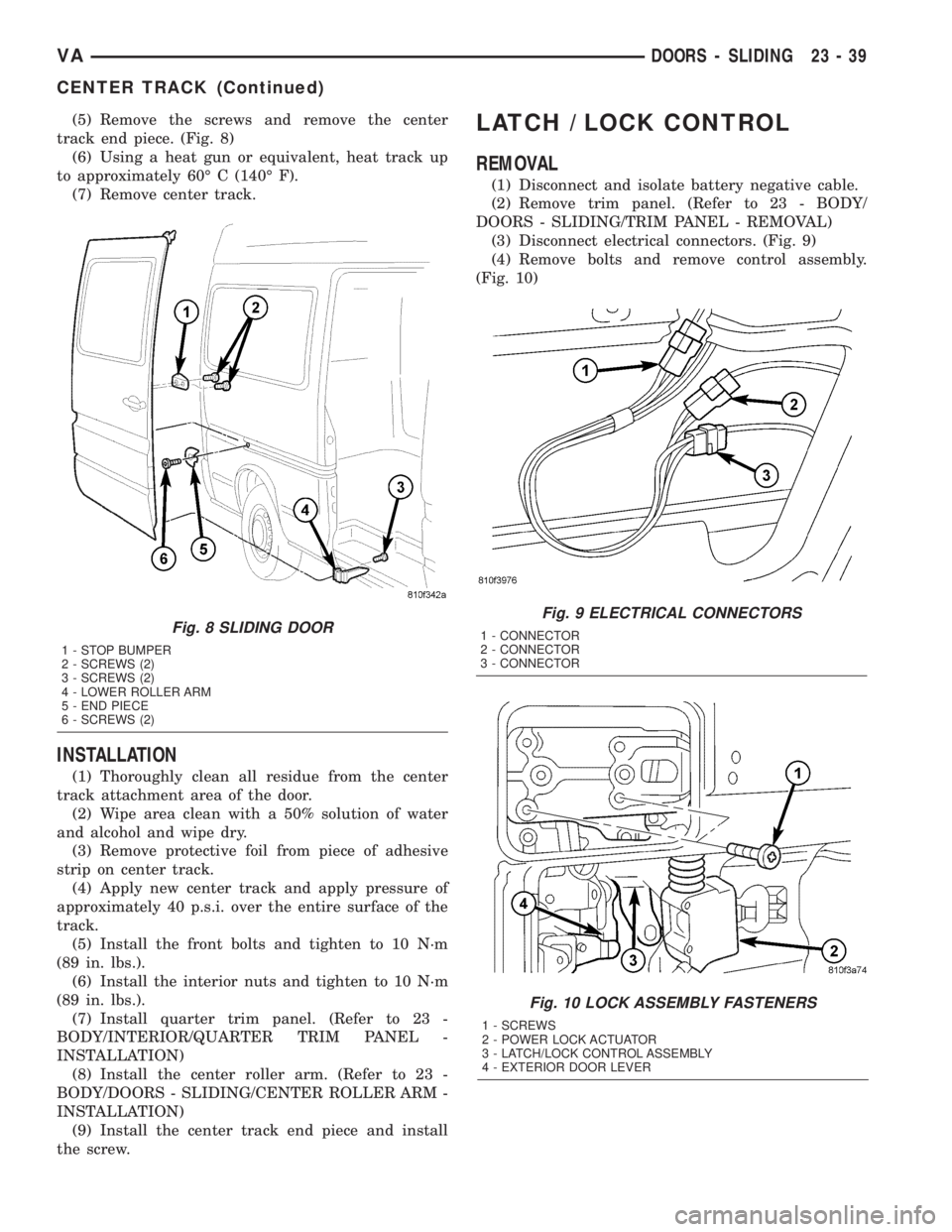
track end piece. (Fig. 8)
(6) Using a heat gun or equivalent, heat track up
to approximately 60É C (140É F).
(7) Remove center track.
INSTALLATION
(1) Thoroughly clean all residue from the center
track attachment area of the door.
(2) Wipe area clean with a 50% solution of water
and alcohol and wipe dry.
(3) Remove protective foil from piece of adhesive
strip on center track.
(4) Apply new center track and apply pressure of
approximately 40 p.s.i. over the entire surface of the
track.
(5) Install the front bolts and tighten to 10 N´m
(89 in. lbs.).
(6) Install the interior nuts and tighten to 10 N´m
(89 in. lbs.).
(7) Install quarter trim panel. (Refer to 23 -
BODY/INTERIOR/QUARTER TRIM PANEL -
INSTALLATION)
(8) Install the center roller arm. (Refer to 23 -
BODY/DOORS - SLIDING/CENTER ROLLER ARM -
INSTALLATION)
(9) Install the center track end piece and install
the screw.
LATCH / LOCK CONTROL
REMOVAL
(1) Disconnect and isolate battery negative cable.
(2) Remove trim panel. (Refer to 23 - BODY/
DOORS - SLIDING/TRIM PANEL - REMOVAL)
(3) Disconnect electrical connectors. (Fig. 9)
(4) Remove bolts and remove control assembly.
(Fig. 10)
Fig. 9 ELECTRICAL CONNECTORS
1 - CONNECTOR
2 - CONNECTOR
3 - CONNECTOR
Fig. 10 LOCK ASSEMBLY FASTENERS
1 - SCREWS
2 - POWER LOCK ACTUATOR
3 - LATCH/LOCK CONTROL ASSEMBLY
4 - EXTERIOR DOOR LEVER
Fig. 8 SLIDING DOOR
1 - STOP BUMPER
2 - SCREWS (2)
3 - SCREWS (2)
4 - LOWER ROLLER ARM
5 - END PIECE
6 - SCREWS (2)
VADOORS - SLIDING 23 - 39
CENTER TRACK (Continued)
Page 1078 of 1232
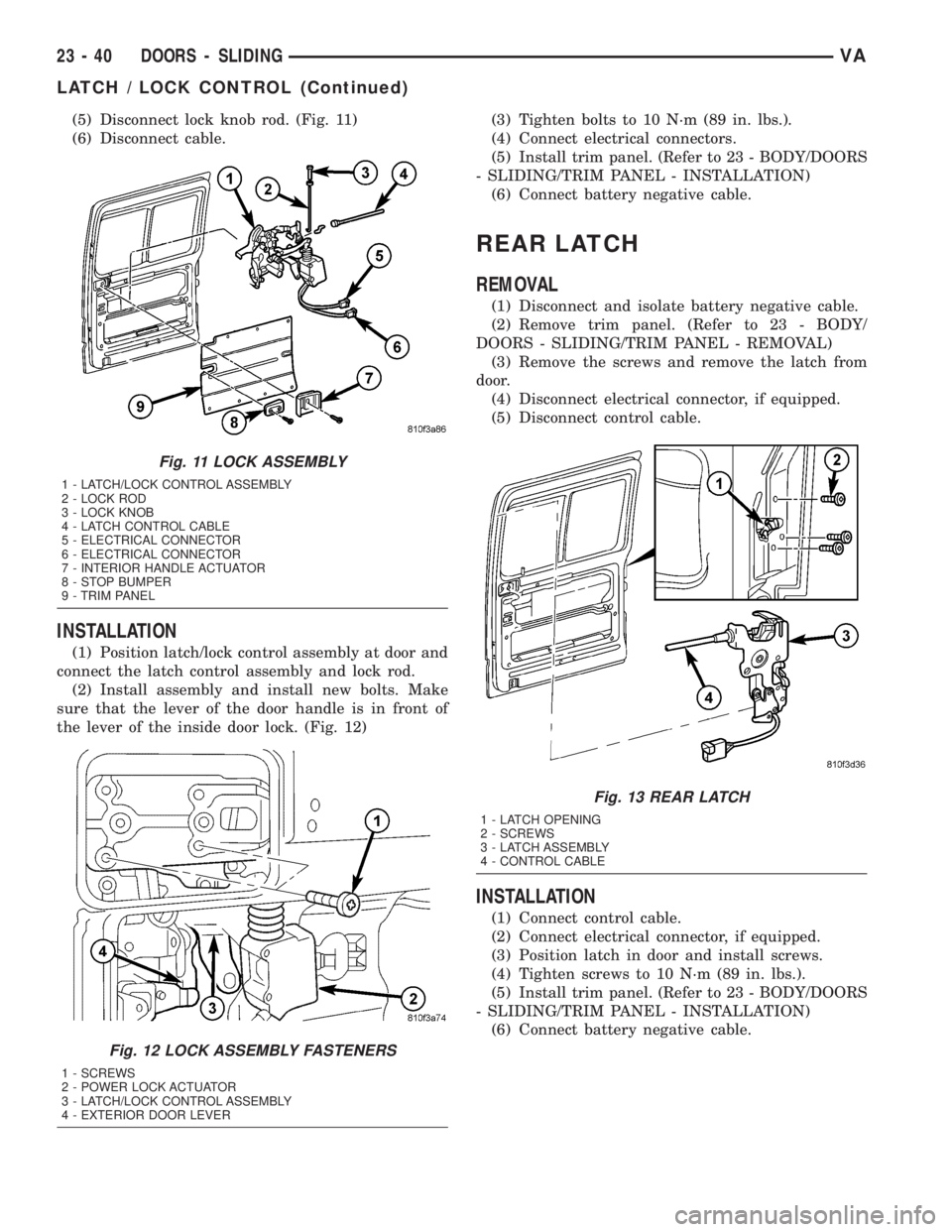
(5) Disconnect lock knob rod. (Fig. 11)
(6) Disconnect cable.
INSTALLATION
(1) Position latch/lock control assembly at door and
connect the latch control assembly and lock rod.
(2) Install assembly and install new bolts. Make
sure that the lever of the door handle is in front of
the lever of the inside door lock. (Fig. 12)(3) Tighten bolts to 10 N´m (89 in. lbs.).
(4) Connect electrical connectors.
(5) Install trim panel. (Refer to 23 - BODY/DOORS
- SLIDING/TRIM PANEL - INSTALLATION)
(6) Connect battery negative cable.
REAR LATCH
REMOVAL
(1) Disconnect and isolate battery negative cable.
(2) Remove trim panel. (Refer to 23 - BODY/
DOORS - SLIDING/TRIM PANEL - REMOVAL)
(3) Remove the screws and remove the latch from
door.
(4) Disconnect electrical connector, if equipped.
(5) Disconnect control cable.
INSTALLATION
(1) Connect control cable.
(2) Connect electrical connector, if equipped.
(3) Position latch in door and install screws.
(4) Tighten screws to 10 N´m (89 in. lbs.).
(5) Install trim panel. (Refer to 23 - BODY/DOORS
- SLIDING/TRIM PANEL - INSTALLATION)
(6) Connect battery negative cable.
Fig. 11 LOCK ASSEMBLY
1 - LATCH/LOCK CONTROL ASSEMBLY
2 - LOCK ROD
3 - LOCK KNOB
4 - LATCH CONTROL CABLE
5 - ELECTRICAL CONNECTOR
6 - ELECTRICAL CONNECTOR
7 - INTERIOR HANDLE ACTUATOR
8 - STOP BUMPER
9 - TRIM PANEL
Fig. 12 LOCK ASSEMBLY FASTENERS
1 - SCREWS
2 - POWER LOCK ACTUATOR
3 - LATCH/LOCK CONTROL ASSEMBLY
4 - EXTERIOR DOOR LEVER
Fig. 13 REAR LATCH
1 - LATCH OPENING
2 - SCREWS
3 - LATCH ASSEMBLY
4 - CONTROL CABLE
23 - 40 DOORS - SLIDINGVA
LATCH / LOCK CONTROL (Continued)
Page 1079 of 1232
REAR LATCH STRIKER
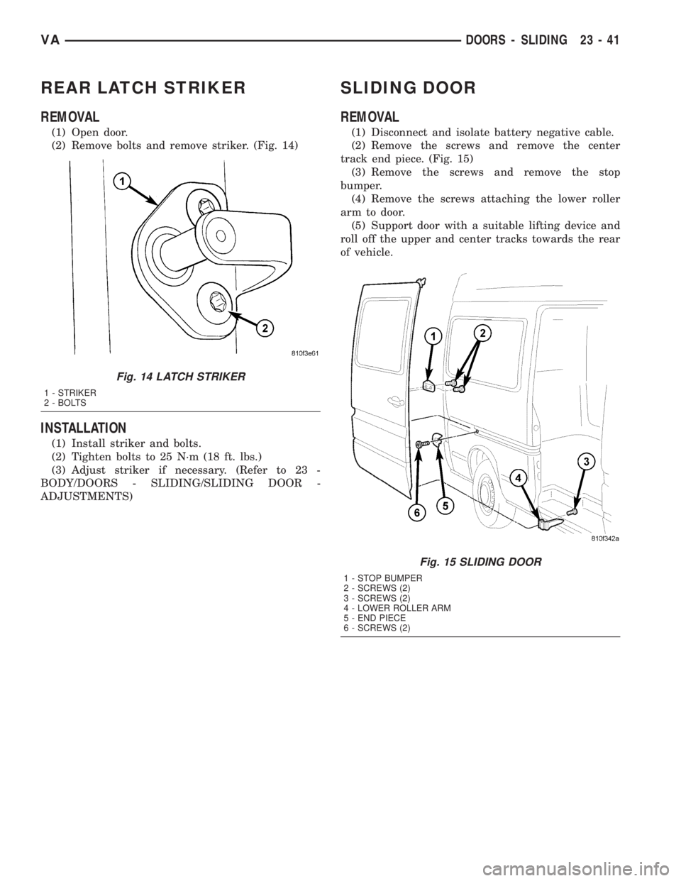
REMOVAL
(1) Open door.
(2) Remove bolts and remove striker. (Fig. 14)
INSTALLATION
(1) Install striker and bolts.
(2) Tighten bolts to 25 N´m (18 ft. lbs.)
(3) Adjust striker if necessary. (Refer to 23 -
BODY/DOORS - SLIDING/SLIDING DOOR -
ADJUSTMENTS)
SLIDING DOOR
REMOVAL
(1) Disconnect and isolate battery negative cable.
(2) Remove the screws and remove the center
track end piece. (Fig. 15)
(3) Remove the screws and remove the stop
bumper.
(4) Remove the screws attaching the lower roller
arm to door.
(5) Support door with a suitable lifting device and
roll off the upper and center tracks towards the rear
of vehicle.
Fig. 14 LATCH STRIKER
1 - STRIKER
2 - BOLTS
Fig. 15 SLIDING DOOR
1 - STOP BUMPER
2 - SCREWS (2)
3 - SCREWS (2)
4 - LOWER ROLLER ARM
5 - END PIECE
6 - SCREWS (2)
VADOORS - SLIDING 23 - 41
Page 1080 of 1232
DISASSEMBLY
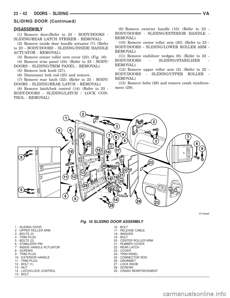
(1) Remove door.(Refer to 23 - BODY/DOORS -
SLIDING/REAR LATCH STRIKER - REMOVAL)
(2) Remove inside door handle actuator (7). (Refer
to 23 - BODY/DOORS - SLIDING/INSIDE HANDLE
ACTUATOR - REMOVAL)
(3) Remove center roller arm cover (23). (Fig. 16)
(4) Remove trim panel (24). (Refer to 23 - BODY/
DOORS - SLIDING/TRIM PANEL - REMOVAL)
(5) Remove lock knob (27).
(6) Disconnect lock rod (25) and remove.
(7) Remove rear latch (22). (Refer to 23 - BODY/
DOORS - SLIDING/REAR LATCH - REMOVAL)
(8) Remove latch/lock control (14). (Refer to 23 -
BODY/DOORS - SLIDING/LATCH / LOCK CON-
TROL - REMOVAL)(9) Remove exterior handle (10). (Refer to 23 -
BODY/DOORS - SLIDING/EXTERIOR HANDLE -
REMOVAL)
(10) Remove center roller arm (20). (Refer to 23 -
BODY/DOORS - SLIDING/LOWER ROLLER ARM -
REMOVAL)
(11) Remove stabilizer wedges (6). (Refer to 23 -
BODY/DOORS - SLIDING/STABILIZER -
REMOVAL)
(12) Remove upper roller arm (2). (Refer to 23 -
BODY/DOORS - SLIDING/UPPER ROLLER -
REMOVAL)
(13) Remove bolts (28) and remove crash reinforce-
ment (29).
Fig. 16 SLIDING DOOR ASSEMBLY
1 - SLIDING DOOR 16 - BOLT
2 - UPPER ROLLER ARM 17 - RELEASE CABLE
3 - BOLTS (2) 18 - WASHER
4 - TRIM PLUG 19 - BOLT
5 - BOLTS (2) 20 - CENTER ROLLER ARM
6 - STABILIZER PIN 21 - RUBBER COVER
7 - INSIDE HANDLE ACTUATOR 22 - REAR LATCH
8 - SCREWS 23 - COVER
9 - TRIM PLUG 24 - TRIM PANEL
10 - EXTERIOR HANDLE 25 - CONNECTOR ROD
11 - TRIM PLUG 26 - GROMMET
12 - BOLT (1) 27 - LOCK KNOB
13 - NUT 28 - SCREWS
14 - LATCH/LOCK CONTROL 29 - CRASH REINFORCEMENT
15 - BOLT
23 - 42 DOORS - SLIDINGVA
SLIDING DOOR (Continued)
Page 1081 of 1232
ASSEMBLY
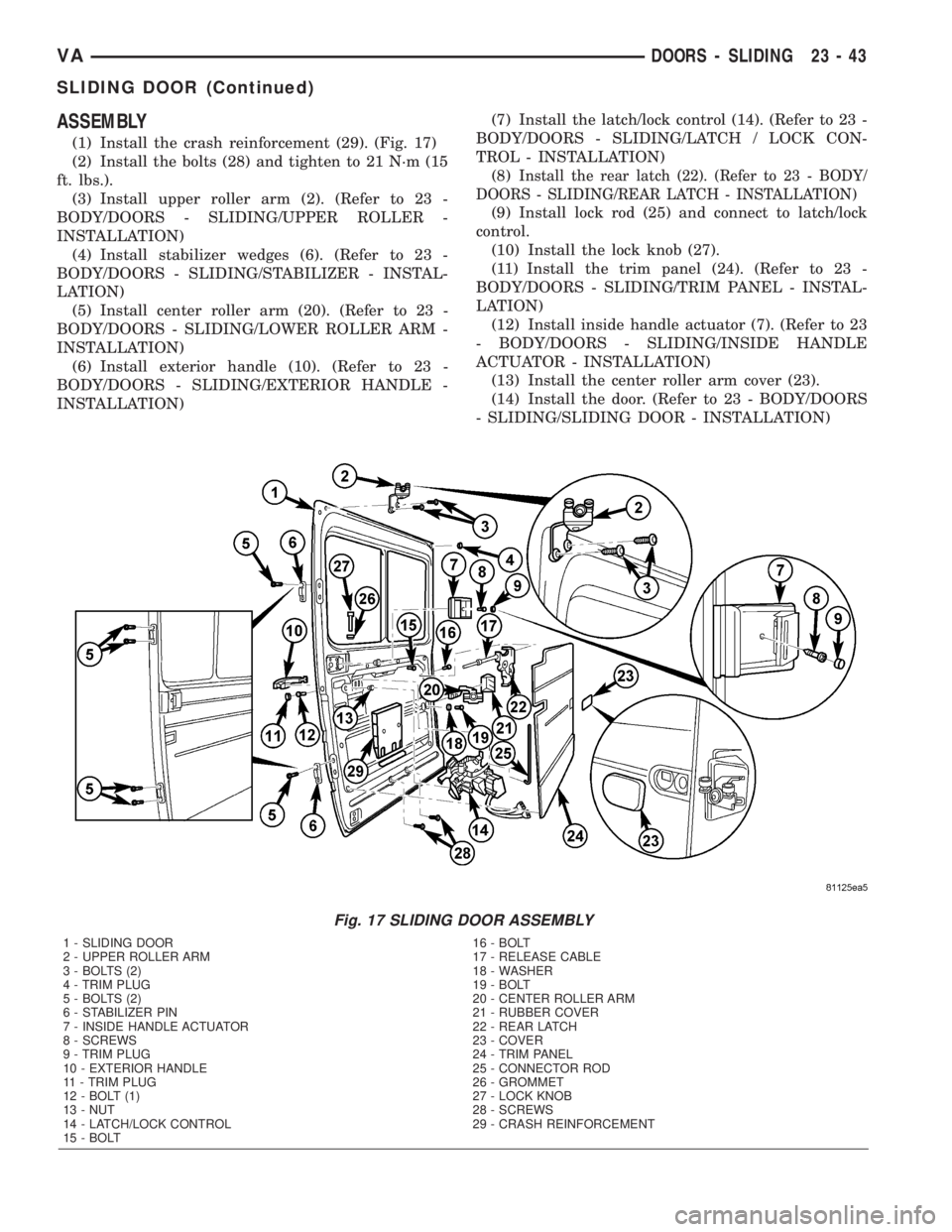
(1) Install the crash reinforcement (29). (Fig. 17)
(2) Install the bolts (28) and tighten to 21 N´m (15
ft. lbs.).
(3) Install upper roller arm (2). (Refer to 23 -
BODY/DOORS - SLIDING/UPPER ROLLER -
INSTALLATION)
(4) Install stabilizer wedges (6). (Refer to 23 -
BODY/DOORS - SLIDING/STABILIZER - INSTAL-
LATION)
(5) Install center roller arm (20). (Refer to 23 -
BODY/DOORS - SLIDING/LOWER ROLLER ARM -
INSTALLATION)
(6) Install exterior handle (10). (Refer to 23 -
BODY/DOORS - SLIDING/EXTERIOR HANDLE -
INSTALLATION)(7) Install the latch/lock control (14). (Refer to 23 -
BODY/DOORS - SLIDING/LATCH / LOCK CON-
TROL - INSTALLATION)
(8)
Install the rear latch (22). (Refer to 23 - BODY/
DOORS - SLIDING/REAR LATCH - INSTALLATION)
(9) Install lock rod (25) and connect to latch/lock
control.
(10) Install the lock knob (27).
(11) Install the trim panel (24). (Refer to 23 -
BODY/DOORS - SLIDING/TRIM PANEL - INSTAL-
LATION)
(12) Install inside handle actuator (7). (Refer to 23
- BODY/DOORS - SLIDING/INSIDE HANDLE
ACTUATOR - INSTALLATION)
(13) Install the center roller arm cover (23).
(14) Install the door. (Refer to 23 - BODY/DOORS
- SLIDING/SLIDING DOOR - INSTALLATION)
Fig. 17 SLIDING DOOR ASSEMBLY
1 - SLIDING DOOR 16 - BOLT
2 - UPPER ROLLER ARM 17 - RELEASE CABLE
3 - BOLTS (2) 18 - WASHER
4 - TRIM PLUG 19 - BOLT
5 - BOLTS (2) 20 - CENTER ROLLER ARM
6 - STABILIZER PIN 21 - RUBBER COVER
7 - INSIDE HANDLE ACTUATOR 22 - REAR LATCH
8 - SCREWS 23 - COVER
9 - TRIM PLUG 24 - TRIM PANEL
10 - EXTERIOR HANDLE 25 - CONNECTOR ROD
11 - TRIM PLUG 26 - GROMMET
12 - BOLT (1) 27 - LOCK KNOB
13 - NUT 28 - SCREWS
14 - LATCH/LOCK CONTROL 29 - CRASH REINFORCEMENT
15 - BOLT
VADOORS - SLIDING 23 - 43
SLIDING DOOR (Continued)
Page 1082 of 1232
INSTALLATION
(1) Install the door by inserting the center and
upper rollers into the tracks and sliding the door for-
ward to the front of each track.
(2) Connect the lower roller arm and install the
screws.
(3) Tighten the screws to 25 N´m (18 ft. lbs.).
(4) Install door stop and screws.
(5) Tighten the screws to 10 N´m (89 in. lbs.).
(6) Install the center track end piece and install
the screw.
(7) Tighten the screw to 10 N´m (89 in. lbs.).
(8) Check and adjust door if necessary. (Refer to 23
- BODY/DOORS - SLIDING/SLIDING DOOR -
ADJUSTMENTS)
(9) Connect battery negative cable.
ADJUSTMENTS
ADJUSTMENT
NOTE: Door adjustment measurements should be
taken from stationary or welded body panels like
the roof, rocker or quarter panels.
A suitable body sealant should be used when
removing or moving the hinges.
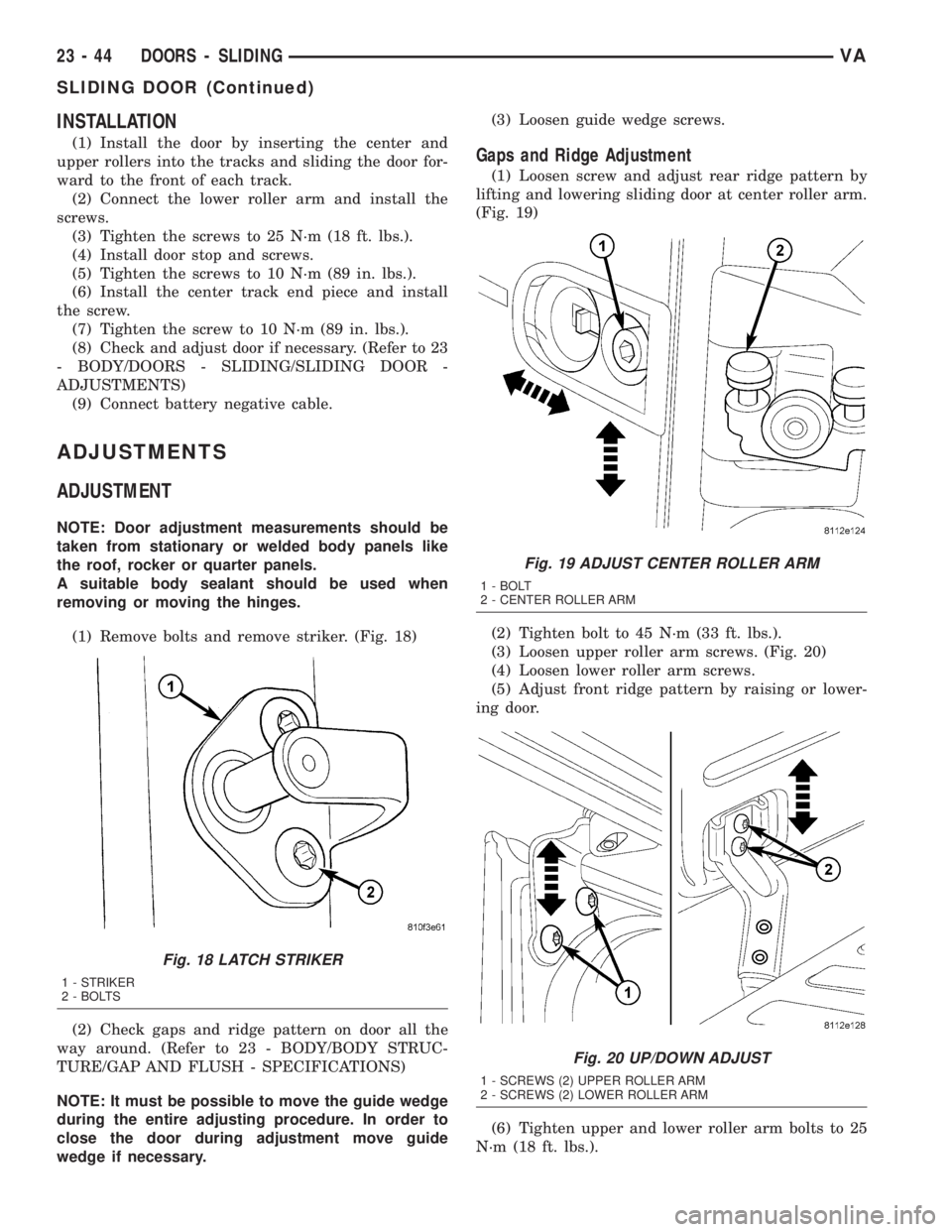
(1) Remove bolts and remove striker. (Fig. 18)
(2) Check gaps and ridge pattern on door all the
way around. (Refer to 23 - BODY/BODY STRUC-
TURE/GAP AND FLUSH - SPECIFICATIONS)
NOTE: It must be possible to move the guide wedge
during the entire adjusting procedure. In order to
close the door during adjustment move guide
wedge if necessary.(3) Loosen guide wedge screws.
Gaps and Ridge Adjustment
(1) Loosen screw and adjust rear ridge pattern by
lifting and lowering sliding door at center roller arm.
(Fig. 19)
(2) Tighten bolt to 45 N´m (33 ft. lbs.).
(3) Loosen upper roller arm screws. (Fig. 20)
(4) Loosen lower roller arm screws.
(5) Adjust front ridge pattern by raising or lower-
ing door.
(6) Tighten upper and lower roller arm bolts to 25
N´m (18 ft. lbs.).
Fig. 18 LATCH STRIKER
1 - STRIKER
2 - BOLTS
Fig. 19 ADJUST CENTER ROLLER ARM
1 - BOLT
2 - CENTER ROLLER ARM
Fig. 20 UP/DOWN ADJUST
1 - SCREWS (2) UPPER ROLLER ARM
2 - SCREWS (2) LOWER ROLLER ARM
23 - 44 DOORS - SLIDINGVA
SLIDING DOOR (Continued)