2005 MERCEDES-BENZ SPRINTER Torque converter
[x] Cancel search: Torque converterPage 125 of 1232
TRANSMISSION CONTROL
MODULE
DESCRIPTION
The transmission control module (TCM) receives,
processes and sends various digital and analog sig-
nals related to the automatic transmission. In addi-
tion, it processes information received from other
vehicle systems, such as engine torque and speed,
accelerator pedal position, wheel speed, kick-down
switch, traction control information, etc.
The TCM is located under the driver's seat and is
connected to other control modules via a CAN bus. It
controls all shift functions to achieve smooth shift
comfort in all driving situations considering:
²Vehicle speed.
²Transmission status.
²Position of selector lever.
²Selected shift range.
²CAN signals.
²Engine Status.Engine speed limits may be reached in all gears
with full throttle or in kick-down operation. In for-
ward driving, the shift range of the forward gears
can be adjusted by the operator by tipping the selec-
tor lever to the left or right (AutoStick). However, the
TCM features a downshift inhibitor to prevent the
engine from overspeeding.
OPERATION
The transmission control module (TCM) deter-
mines the current operating conditions of the vehicle
and controls the shifting process for shift comfort and
driving situations. It receives this operating data
from sensors and broadcast messages from other
modules.
The TCM uses inputs from several sensors that are
directly hardwired to the controller and it uses sev-
eral indirect inputs that are used to control shifts.
This information is used to actuate the proper sole-
noids in the valve body to achieve the desired gear.
The shift lever assembly (SLA) has several items
that are monitored by the TCM to calculate shift
lever position. The reverse light switch, an integral
part of the SLA, controls the reverse light relay con-
trol circuit. The Brake/Transmission Shift Interlock
(BTSI) solenoid and the park lockout solenoid (also
part of the SLA) are controlled by the TCM.
The ECM and ABS broadcast messages over the
controller area network (CAN C) bus for use by the
TCM. The TCM uses this information, with other
inputs, to determine the transmission operating con-
ditions.
The TCM:
²determines the momentary operating conditions
of the vehicle.
²controls all shift processes.
²considers shift comfort and the driving situation.
The TCM controls the solenoid valves for modulat-
ing shift pressures and gear changes. Relative to the
torque being transmitted, the required pressures are
calculated from load conditions, engine rpm, vehicle
speed, and ATF temperature.
The following functions are contained in the TCM:
²Shift Program
²Downshift Safety
²Torque Converter Lock-Up Clutch.
²Adaptation.
This transmission does not have a TCM relay.
Power is supplied to the SLA and the TCM directly
from the ignition.
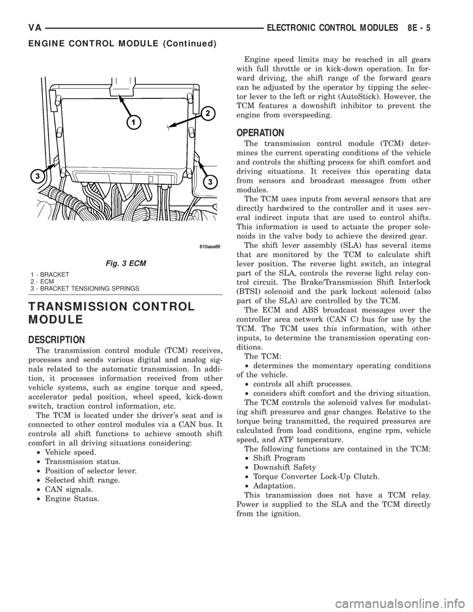
Fig. 3 ECM
1 - BRACKET
2 - ECM
3 - BRACKET TENSIONING SPRINGS
VAELECTRONIC CONTROL MODULES 8E - 5
ENGINE CONTROL MODULE (Continued)
Page 127 of 1232
²Low and High ATF Temperature.
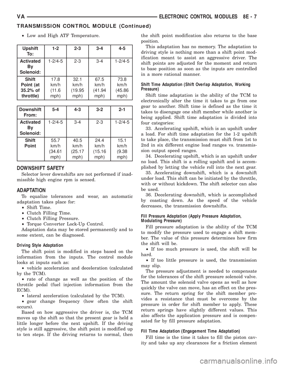
Upshift
To :1-2 2-3 3-4 4-5
Activated
By
Solenoid:1-2/4-5 2-3 3-4 1-2/4-5
Shift
Point (at
35.2% of
throttle)17.8
km/h
(11.6
mph)32.1
km/h
(19.95
mph)67.5
km/h
(41.94
mph)73.8
km/h
(45.86
mph)
Downshift
From:5-4 4-3 3-2 2-1
Activated
By
Solenoid:1-2/4-5 3-4 2-3 1-2/4-5
Shift
Point55.7
km/h
(34.61
mph)40.5
km/h
(25.17
mph)24.4
km/h
(15.16
mph)15.1
km/h
(9.38
mph)
DOWNSHIFT SAFETY
Selector lever downshifts are not performed if inad-
missible high engine rpm is sensed.
ADAPTATION
To equalize tolerances and wear, an automatic
adaptation takes place for:
²Shift Time.
²Clutch Filling Time.
²Clutch Filling Pressure.
²Torque Converter Lock-Up Control.
Adaptation data may be stored permanently and to
some extent, can be diagnosed.
Driving Style Adaptation
The shift point is modified in steps based on the
information from the inputs. The control module
looks at inputs such as:
²vehicle acceleration and deceleration (calculated
by the TCM).
²rate of change as well as the position of the
throttle pedal (fuel injection information from the
ECM).
²lateral acceleration (calculated by the TCM).
²gear change frequency (how often the shift
occurs).
Based on how aggressive the driver is, the TCM
moves up the shift so that the present gear is held a
little longer before the next upshift. If the driving
style is still aggressive, the shift point is modified up
to ten steps. If the driving returns to normal, thenthe shift point modification also returns to the base
position.
This adaptation has no memory. The adaptation to
driving style is nothing more than a shift point mod-
ification meant to assist an aggressive driver. The
shift points are adjusted for the moment and return
to base position as soon as the inputs are controlled
in a more rational manner.
Shift Time Adaptation (Shift Overlap Adaptation, Working
Pressure)
Shift time adaptation is the ability of the TCM to
electronically alter the time it takes to go from one
gear to another. Shift time is defined as the time it
takes to disengage one shift member while another is
being applied. Shift time adaptation is divided into
four categories:
33. Accelerating upshift, which is an upshift under
a load. For shift time adaptation for the 1-2 upshift
to take place, the transmission must shift from 1st to
2nd in six different engine load ranges vs. transmis-
sion output speed ranges.
34. Decelerating upshift, which is an upshift under
no load. This shift is a rolling upshift and is accom-
plished by letting the vehicle roll into the next gear.
35. Accelerating downshift, which is a downshift
under load. This shift can be initiated by the throttle,
with or without kickdown. The shift selector can also
be used.
36. Decelerating downshift, which is accomplished
by coasting down. As the speed of the vehicle
decreases, the transmission downshifts.
Fill Pressure Adaptation (Apply Pressure Adaptation,
Modulating Pressure)
Fill pressure adaptation is the ability of the TCM
to modify the pressure used to engage a shift mem-
ber. The value of this pressure determines how firm
the shift will be.
²If too much pressure is used, the shift will be
hard.
²If too little pressure is used, the transmission
may slip.
The pressure adjustment is needed to compensate
for the tolerances of the shift pressure solenoid valve.
The amount the solenoid valve opens as well as how
quickly the valve can move, has an effect on the pres-
sure. The return spring for the shift member pro-
vides a resistance that must be overcome by the
pressure in order for shift member to apply. These
return springs have slightly different values. This
also affects the application pressure and is compen-
sated for by fill pressure adaptation.
Fill Time Adaptation (Engagement Time Adaptation)
Fill time is the time it takes to fill the piston cav-
ity and take up any clearances for a friction element
VAELECTRONIC CONTROL MODULES 8E - 7
TRANSMISSION CONTROL MODULE (Continued)
Page 152 of 1232
STARTING SYSTEM
TABLE OF CONTENTS
page page
STARTING SYSTEM
DESCRIPTION.........................24
OPERATION...........................24
DIAGNOSIS AND TESTING - STARTING
SYSTEM............................25
SPECIFICATIONS
TORQUE - STARTER - DIESEL...........29
SPECIFICATIONS - STARTER MOTOR -
DIESEL.............................29STARTER MOTOR
DIAGNOSIS AND TESTING - STARTER
MOTOR .............................29
REMOVAL.............................30
INSTALLATION.........................31
STARTER MOTOR RELAY
DESCRIPTION.........................31
REMOVAL.............................31
INSTALLATION.........................32
STARTING SYSTEM
DESCRIPTION
The starting system consists of:
²Starter relay
²Starter motor (including an integral starter sole-
noid)
Other components to be considered as part of start-
ing system are:
²Battery
²Battery cables
²Ignition switch and key lock cylinder
²Park/neutral position switch (automatic trans-
mission)
²Wire harnesses and connections.
The Battery, Starting, and Charging systems oper-
ate in conjunction with one another, and must be
tested as a complete system. For correct operation of
starting/charging systems, all components used in
these 3 systems must perform within specifications.
When attempting to diagnose any of these systems, it
is important that you keep their interdependency in
mind.
The diagnostic procedures used in each of these
groups include the most basic conventional diagnostic
methods, to the more sophisticated On-Board Diag-
nostics (OBD) built into the Engine Control Module
(ECM). Use of an induction-type milliampere amme-
ter, volt/ohmmeter, battery charger, carbon pile rheo-
stat (load tester), and 12-volt test lamp may be
required.
Certain starting system components are monitored
by the ECM and may produce a Diagnostic Trouble
Code (DTC).
OPERATION
The starting system components form two separate
circuits. A high-amperage feed circuit that feeds thestarter motor high-amperage, and a low-amperage
control circuit that operates on less than 20 amperes.
The high-amperage feed circuit components include
the battery, the battery cables, the contact disc por-
tion of the starter solenoid, and the starter motor
itself. The low-amperage control circuit components
include the ignition switch, the park/neutral position
switch (automatic transmission), the starter relay,
the electromagnetic windings of the starter solenoid,
and the connecting wire harness components.
If the vehicle is equipped with an automatic trans-
mission, battery voltage is supplied through the low-
amperage control circuit to the coil battery terminal
of the starter relay when the ignition switch is
turned to the momentary Start position. The park/
neutral position switch is installed in series between
the starter relay coil ground terminal and ground.
This normally open switch prevents the starter relay
from being energized and the starter motor from
operating unless the automatic transmission gear
selector is in the Neutral or Park positions.
When the starter relay coil is energized, the nor-
mally open relay contacts close. The relay contacts
connect the relay common feed terminal to the relay
normally open terminal. The closed relay contacts
energize the starter solenoid coil windings.
The energized solenoid pull-in coil pulls in the sole-
noid plunger. The solenoid plunger pulls the shift
lever in the starter motor. This engages the starter
overrunning clutch and pinion gear with the starter
ring gear on the manual transmission flywheel or on
the automatic transmission torque converter or
torque converter drive plate.
As the solenoid plunger reaches the end of its
travel, the solenoid contact disc completes the high-
amperage starter feed circuit and energizes the sole-
noid plunger hold-in coil. Current now flows between
the solenoid battery terminal and the starter motor,
energizing the starter.
8F - 24 STARTING SYSTEMVA
Page 744 of 1232
(15) Disconnect the coolant hose of the heater sup-
ply at the coolant pipe at the side of the cylinder
head (Fig. 3).
(16) Disconnect the vacuum hose at the turbo-
charger (Fig. 3).
(17) Disconnect the air inlet hose at the turbo-
charger (Fig. 3).
(18) Raise and support the vehicle.
(19) Disconnect the front exhaust at the turbo-
charger.
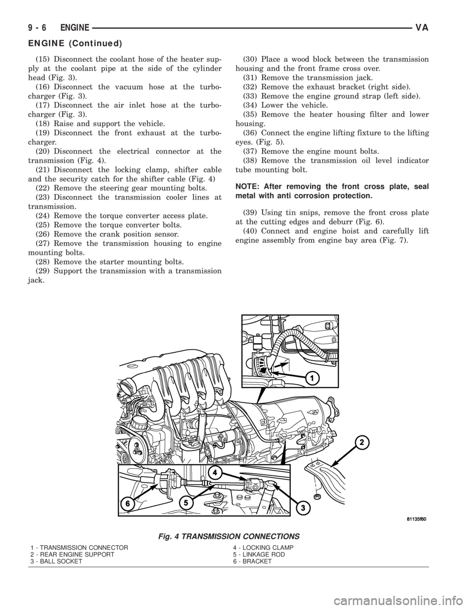
(20) Disconnect the electrical connector at the
transmission (Fig. 4).
(21) Disconnect the locking clamp, shifter cable
and the security catch for the shifter cable (Fig. 4)
(22) Remove the steering gear mounting bolts.
(23) Disconnect the transmission cooler lines at
transmission.
(24) Remove the torque converter access plate.
(25) Remove the torque converter bolts.
(26) Remove the crank position sensor.
(27) Remove the transmission housing to engine
mounting bolts.
(28) Remove the starter mounting bolts.
(29) Support the transmission with a transmission
jack.(30) Place a wood block between the transmission
housing and the front frame cross over.
(31) Remove the transmission jack.
(32) Remove the exhaust bracket (right side).
(33) Remove the engine ground strap (left side).
(34) Lower the vehicle.
(35) Remove the heater housing filter and lower
housing.
(36) Connect the engine lifting fixture to the lifting
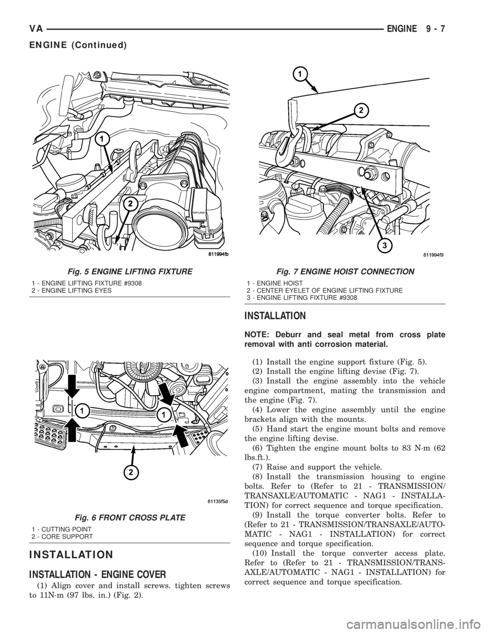
eyes. (Fig. 5).
(37) Remove the engine mount bolts.
(38) Remove the transmission oil level indicator
tube mounting bolt.
NOTE: After removing the front cross plate, seal
metal with anti corrosion protection.
(39) Using tin snips, remove the front cross plate
at the cutting edges and deburr (Fig. 6).
(40) Connect and engine hoist and carefully lift
engine assembly from engine bay area (Fig. 7).
Fig. 4 TRANSMISSION CONNECTIONS
1 - TRANSMISSION CONNECTOR 4 - LOCKING CLAMP
2 - REAR ENGINE SUPPORT 5 - LINKAGE ROD
3 - BALL SOCKET 6 - BRACKET
9 - 6 ENGINEVA
ENGINE (Continued)
Page 745 of 1232
INSTALLATION
INSTALLATION - ENGINE COVER
(1) Align cover and install screws. tighten screws
to 11N´m (97 lbs. in.) (Fig. 2).
INSTALLATION
NOTE: Deburr and seal metal from cross plate
removal with anti corrosion material.
(1) Install the engine support fixture (Fig. 5).
(2) Install the engine lifting devise (Fig. 7).
(3) Install the engine assembly into the vehicle
engine compartment, mating the transmission and
the engine (Fig. 7).
(4) Lower the engine assembly until the engine
brackets align with the mounts.
(5) Hand start the engine mount bolts and remove
the engine lifting devise.
(6) Tighten the engine mount bolts to 83 N´m (62
lbs.ft.).
(7) Raise and support the vehicle.
(8) Install the transmission housing to engine
bolts. Refer to (Refer to 21 - TRANSMISSION/
TRANSAXLE/AUTOMATIC - NAG1 - INSTALLA-
TION) for correct sequence and torque specification.
(9) Install the torque converter bolts. Refer to
(Refer to 21 - TRANSMISSION/TRANSAXLE/AUTO-
MATIC - NAG1 - INSTALLATION) for correct
sequence and torque specification.
(10) Install the torque converter access plate.
Refer to (Refer to 21 - TRANSMISSION/TRANS-
AXLE/AUTOMATIC - NAG1 - INSTALLATION) for
correct sequence and torque specification.
Fig. 5 ENGINE LIFTING FIXTURE
1 - ENGINE LIFTING FIXTURE #9308
2 - ENGINE LIFTING EYES
Fig. 6 FRONT CROSS PLATE
1 - CUTTING POINT
2 - CORE SUPPORT
Fig. 7 ENGINE HOIST CONNECTION
1 - ENGINE HOIST
2 - CENTER EYELET OF ENGINE LIFTING FIXTURE
3 - ENGINE LIFTING FIXTURE #9308
VAENGINE 9 - 7
ENGINE (Continued)
Page 878 of 1232
OUTPUT SHAFT SEAL
REMOVAL............................125
INSTALLATION........................125
PARK LOCK CABLE
REMOVAL............................125
INSTALLATION........................126
PISTONS
DESCRIPTION........................128
OPERATION..........................128
PLANETARY GEARTRAIN
DESCRIPTION........................130
OPERATION..........................130
DISASSEMBLY........................131
ASSEMBLY...........................131
SHIFT MECHANISM
DESCRIPTION........................133
OPERATION..........................133
REMOVAL............................134
INSTALLATION........................135
SOLENOID
DESCRIPTION........................136OPERATION..........................138
TEMPERATURE SENSOR/PARK-NEUTRAL
CONTACT
DESCRIPTION
DESCRIPTION - PARK/NEUTRAL CONTACT . 139
DESCRIPTION - TRANSMISSION
TEMPERATURE SENSOR..............140
OPERATION
OPERATION - PARK/NEUTRAL CONTACT . . 140
OPERATION - TRANSMISSION
TEMPERATURE SENSOR..............141
TORQUE CONVERTER
DESCRIPTION........................141
OPERATION..........................143
REMOVAL............................146
INSTALLATION........................146
TORQUE CONVERTER HUB SEAL
REMOVAL............................147
INSTALLATION........................147
AUTOMATIC TRANSMISSION -
NAG1
DESCRIPTION
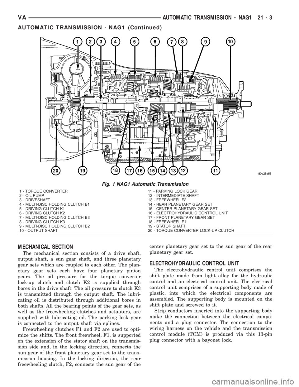
The NAG1 automatic transmission (Fig. 1) is an
electronically controlled 5-speed transmission with a
lock-up clutch in the torque converter. The ratios for
the gear stages are obtained by 3 planetary gear sets.
Fifth gear is designed as an overdrive with a high-
speed ratio.
The gears are actuated electronically/hydraulically.
The gears are shifted by means of an appropriate
combination of three multi-disc holding clutches,
three multi-disc driving clutches, and two freewheel-
ing clutches.
Electronic transmission control enables precise
adaptation of pressures to the respective operating
conditions and to the engine output during the shift
phase which results in a significant improvement in
shift quality.
Furthermore, it offers the advantage of a flexible
adaptation to various vehicle and engines.
Basically, the automatic transmission with elec-
tronic control offers the following advantages:
²Reduces fuel consumption.
²Improved shift comfort.
²More favourable step-up through the five gears.
²Increased service life and reliability.
²Lower maintenance costs.
TRANSMISSION IDENTIFICATION
The transmission name, NAG1, means New Auto-
matic Gearbox, generation 1.
The transmission can be generically identified
visually by the presence of a round 13-way connector
located near the front corner of the transmission oil
pan, on the right side. Specific transmission informa-
tion can be found stamped into a pad on the left side
of the transmission, above the oil pan rail.
TRANSMISSION GEAR RATIOS
The gear ratios for the NAG1 automatic transmis-
sion are as follows:
1st Gear.............................3.59:1
2nd Gear............................2.19:1
3rd Gear............................1.41:1
4th Gear............................1.00:1
5th Gear............................0.83:1
Reverse.............................3.16:1
TRANSMISSION HOUSING
The converter housing and transmission are made
from a light alloy. These are bolted together and cen-
tered via the outer multi-disc carrier of multi-disc
holding clutch, B1. A coated intermediate plate pro-
vides the sealing. The oil pump and the outer multi-
disc carrier of the multi-disc holding clutch, B1, are
bolted to the converter housing. The stator shaft is
pressed into it and prevented from rotating by
splines. The electrohydraulic unit is bolted to the
transmission housing from underneath. A sheet
metal steel oil pan forms the closure.
21 - 2 AUTOMATIC TRANSMISSION - NAG1VA
Page 879 of 1232
MECHANICAL SECTION
The mechanical section consists of a drive shaft,
output shaft, a sun gear shaft, and three planetary
gear sets which are coupled to each other. The plan-
etary gear sets each have four planetary pinion
gears. The oil pressure for the torque converter
lock-up clutch and clutch K2 is supplied through
bores in the drive shaft. The oil pressure to clutch K3
is transmitted through the output shaft. The lubri-
cating oil is distributed through additional bores in
both shafts. All the bearing points of the gear sets, as
well as the freewheeling clutches and actuators, are
supplied with lubricating oil. The parking lock gear
is connected to the output shaft via splines.
Freewheeling clutches F1 and F2 are used to opti-
mize the shifts. The front freewheel, F1, is supported
on the extension of the stator shaft on the transmis-
sion side and, in the locking direction, connects the
sun gear of the front planetary gear set to the trans-
mission housing. In the locking direction, the rear
freewheeling clutch, F2, connects the sun gear of thecenter planetary gear set to the sun gear of the rear
planetary gear set.
ELECTROHYDRAULIC CONTROL UNIT
The electrohydraulic control unit comprises the
shift plate made from light alloy for the hydraulic
control and an electrical control unit. The electrical
control unit comprises of a supporting body made of
plastic, into which the electrical components are
assembled. The supporting body is mounted on the
shift plate and screwed to it.
Strip conductors inserted into the supporting body
make the connection between the electrical compo-
nents and a plug connector. The connection to the
wiring harness on the vehicle and the transmission
control module (TCM) is produced via this 13-pin
plug connector with a bayonet lock.
Fig. 1 NAG1 Automatic Transmission
1 - TORQUE CONVERTER 11 - PARKING LOCK GEAR
2 - OIL PUMP 12 - INTERMEDIATE SHAFT
3 - DRIVESHAFT 13 - FREEWHEEL F2
4 - MULTI-DISC HOLDING CLUTCH B1 14 - REAR PLANETARY GEAR SET
5 - DRIVING CLUTCH K1 15 - CENTER PLANETARY GEAR SET
6 - DRIVING CLUTCH K2 16 - ELECTROHYDRAULIC CONTROL UNIT
7 - MULTI-DISC HOLDING CLUTCH B3 17 - FRONT PLANETARY GEAR SET
8 - DRIVING CLUTCH K3 18 - FREEWHEEL F1
9 - MULTI-DISC HOLDING CLUTCH B2 19 - STATOR SHAFT
10 - OUTPUT SHAFT 20 - TORQUE CONVERTER LOCK-UP CLUTCH
VAAUTOMATIC TRANSMISSION - NAG1 21 - 3
AUTOMATIC TRANSMISSION - NAG1 (Continued)
Page 880 of 1232
SHIFT GROUPS
The hydraulic control components (including actua-
tors) which are responsible for the pressure distribu-
tion before, during, and after a gear change are
described as a shift group. Each shift group contains
a command valve, a holding pressure shift valve, a
shift pressure shift valve, overlap regulating valve,
and a solenoid.
The hydraulic system contains three shift groups:
1-2/4-5, 2-3, and 3-4. Each shift group can also be
described as being in one of two possible states. The
active shift group is described as being in the shift
phase when it is actively engaging/disengaging a
clutch combination. The 1-2/4-5 shift group control
the B1 and K1 clutches. The 2-3 shift group controls
the K2 and K3 clutches. The 3-4 shift group controls
the K3 and B2 clutches.
OPERATION
The transmission control is divided into the elec-
tronic and hydraulic transmission control functions.
While the electronic transmission control is responsi-
ble for gear selection and for matching the pressures
to the torque to be transmitted, the transmission's
power supply control occurs via hydraulic elements
in the electrohydraulic control module. The oil supply
to the hydraulic elements, such as the hydrodynamic
torque converter, the shift elements and the hydrau-
lic transmission control, is provided by way of an oil
pump connected with the torque converter.
The Transmission Control Module (TCM) allows for
the precise adaptation of pressures to the correspond-
ing operating conditions and to the engine output
during the gearshift phase, resulting in a noticeable
improvement in shift quality. The engine speed limit
can be reached in the individual gears at full throttle
and kickdown. The shift range can be changed in the
forward gears while driving, but the TCM employs adownshift safeguard to prevent over-revving the
engine. The system offers the additional advantage of
flexible adaptation to different vehicle and engine
variants.
EMERGENCY RUNNING FUNCTION
In order to ensure a safe driving state and to pre-
vent damage to the automatic transmission, the TCM
control module switches to limp-home mode in the
event of critical faults. A DTC assigned to the fault is
stored in memory. All solenoid and regulating valves
are thus de-energized.
The net effect is:
²The last engaged gear remains engaged.
²The modulating pressure and shift pressures
rise to the maximum levels.
²The torque converter lockup clutch is deacti-
vated.
In order to preserve the operability of the vehicle
to some extent, the hydraulic control can be used to
engage 2nd gear or reverse using the following pro-
cedure:
²Stop the vehicle.
²Switch off engine.
²Move selector lever to9P9.
²Wait at least 10 seconds.
²Start engine.
²Move selector lever to D: 2nd gear.
²Move selector lever to R: Reverse gear.
The limp-home function remains active until the
DTC is rectified or the stored DTC is erased with the
DRBttool. Sporadic faults can be reset via ignition
OFF/ON.
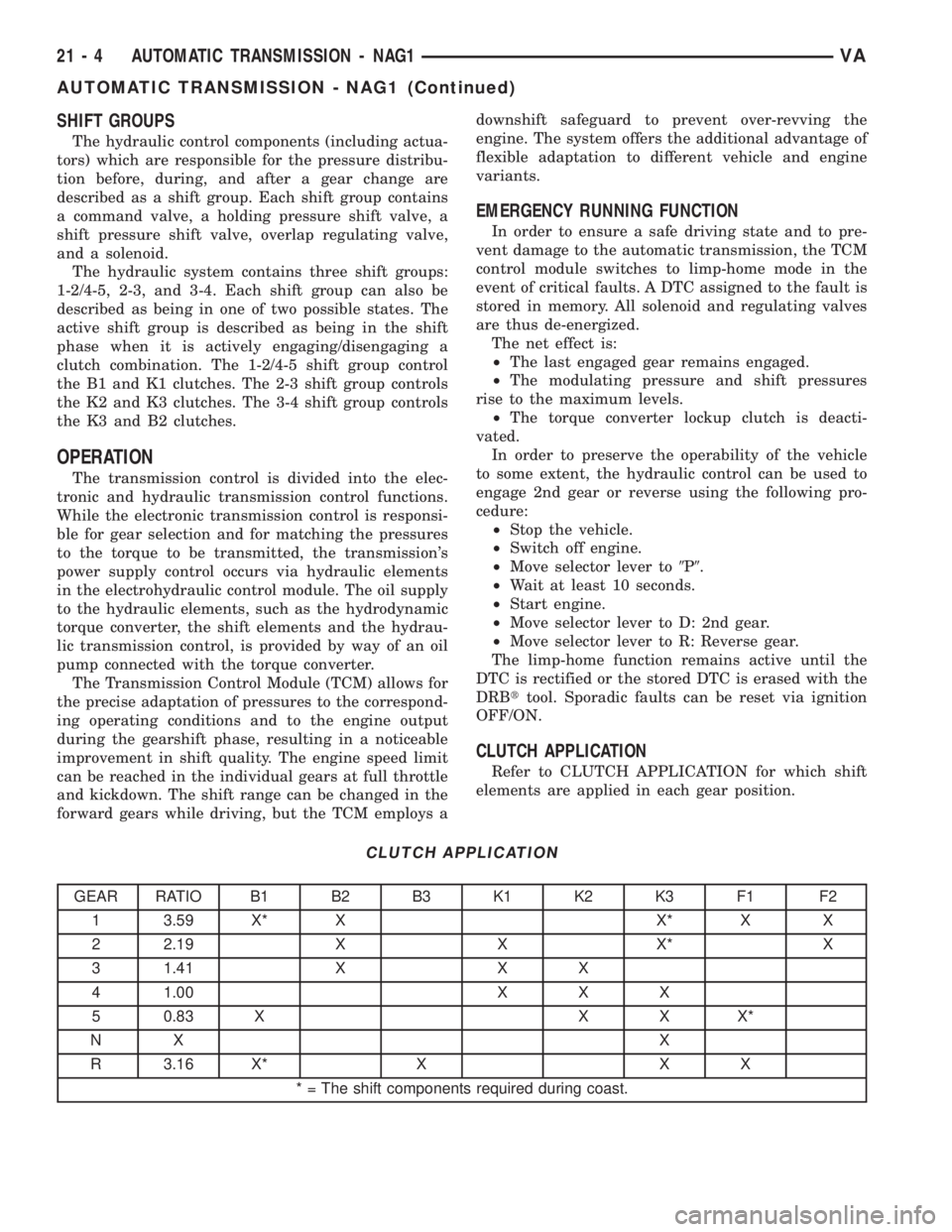
CLUTCH APPLICATION
Refer to CLUTCH APPLICATION for which shift
elements are applied in each gear position.
CLUTCH APPLICATION
GEAR RATIO B1 B2 B3 K1 K2 K3 F1 F2
1 3.59 X* X X* X X
2 2.19 X X X* X
3 1.41 X X X
4 1.00 X X X
5 0.83 X X X X*
NX X
R 3.16 X* X X X
* = The shift components required during coast.
21 - 4 AUTOMATIC TRANSMISSION - NAG1VA
AUTOMATIC TRANSMISSION - NAG1 (Continued)