2005 MERCEDES-BENZ SPRINTER wheel bolts
[x] Cancel search: wheel boltsPage 52 of 1232
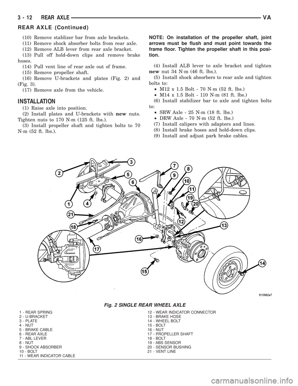
(10) Remove stablizer bar from axle brackets.
(11) Remove shock absorber bolts from rear axle.
(12) Remove ALB lever from rear axle bracket.
(13) Pull off hold-down clips and remove brake
hoses.
(14) Pull vent line of rear axle out of frame.
(15) Remove propeller shaft.
(16) Remove U-brackets and plates (Fig. 2) and
(Fig. 3).
(17) Remove axle from the vehicle.
INSTALLATION
(1) Raise axle into position.
(2) Install plates and U-brackets withnewnuts.
Tighten nuts to 170 N´m (125 ft. lbs.).
(3) Install propeller shaft and tighten bolts to 70
N´m (52 ft. lbs.).NOTE: On installation of the propeller shaft, joint
arrows must be flush and must point towards the
frame floor. Tighten the propeller shaft in this posi-
tion.
(4) Install ALB lever to axle bracket and tighten
newnut 34 N´m (46 ft. lbs.).
(5) Install shock absorbers to rear axle and tighten
bolts to:
²M12 x 1.5 Bolt - 70 N´m (52 ft. lbs.)
²M14 x 1.5 Bolt - 110 N´m (81 ft. lbs.)
(6) Install stabilizer bar to axle and tighten bolts
to:
²SRW Axle - 25 N´m (18 ft. lbs.)
²DRW Axle - 70 N´m (52 ft. lbs.)
(7) Install calipers with adapters and lines.
(8) Install brake hoses and hold-down clips.
(9) Install and adjust park brake cables.
Fig. 2 SINGLE REAR WHEEL AXLE
1 - REAR SPRING 12 - WEAR INDICATOR CONNECTOR
2 - U-BRACKET 13 - BRAKE HOSE
3 - PLATE 14 - WHEEL BOLT
4 - NUT 15 - BOLT
5 - BRAKE CABLE 16 - NUT
6 - REAR AXLE 17 - PROPELLER SHAFT
7 - ABL LEVER 18 - BOLT
8 - NUT 19 - ABS SENSOR
9 - SHOCK ABSORBER 20 - SENSOR BUSHING
10 - BOLT 21 - VENT LINE
11 - WEAR INDICATOR CABLE
3 - 12 REAR AXLEVA
REAR AXLE (Continued)
Page 55 of 1232
AXLE SHAFTS
REMOVAL
(1) Remove wheels.
(2) Detach front brake cable.
(3) Pull ABS sensor together with clamp bushing
out of bearing cap (Fig. 4).
(4) Remove brake disk at rear axle. Attach brake
caliper with lines connected in wheel house.
(5) Remove brake shoes of parking brake.
(6) Remove brake control cable lock.
(7) Remove bearing cap bolts and pull axle shaft
out of axle tube (Fig. 4).
(8) Remove seal/gasket.
INSTALLATION
(1) Install sealing ring.
(2) Install rear axle shaft in the axle tube (Fig. 5).
(3) Installnewbearing cap bolts and tighten to 72
N´m (53 ft. lbs.) (Fig. 6).
NOTE: Tighten bolts diagonally across.
(4) Install brake control cable lock.
(5) Install parking brake shoes.
(6) Install brake disk and calipers.
(7) Coat clamping bush with acid-free grease.
Insert ABS sensor with clamping bush fully into the
mounting hole.
(8) Install front brake cable.
(9) Operate brake pedal several times until brake
pads contact brake discs (brake pressure built up).
(10) Install wheels.
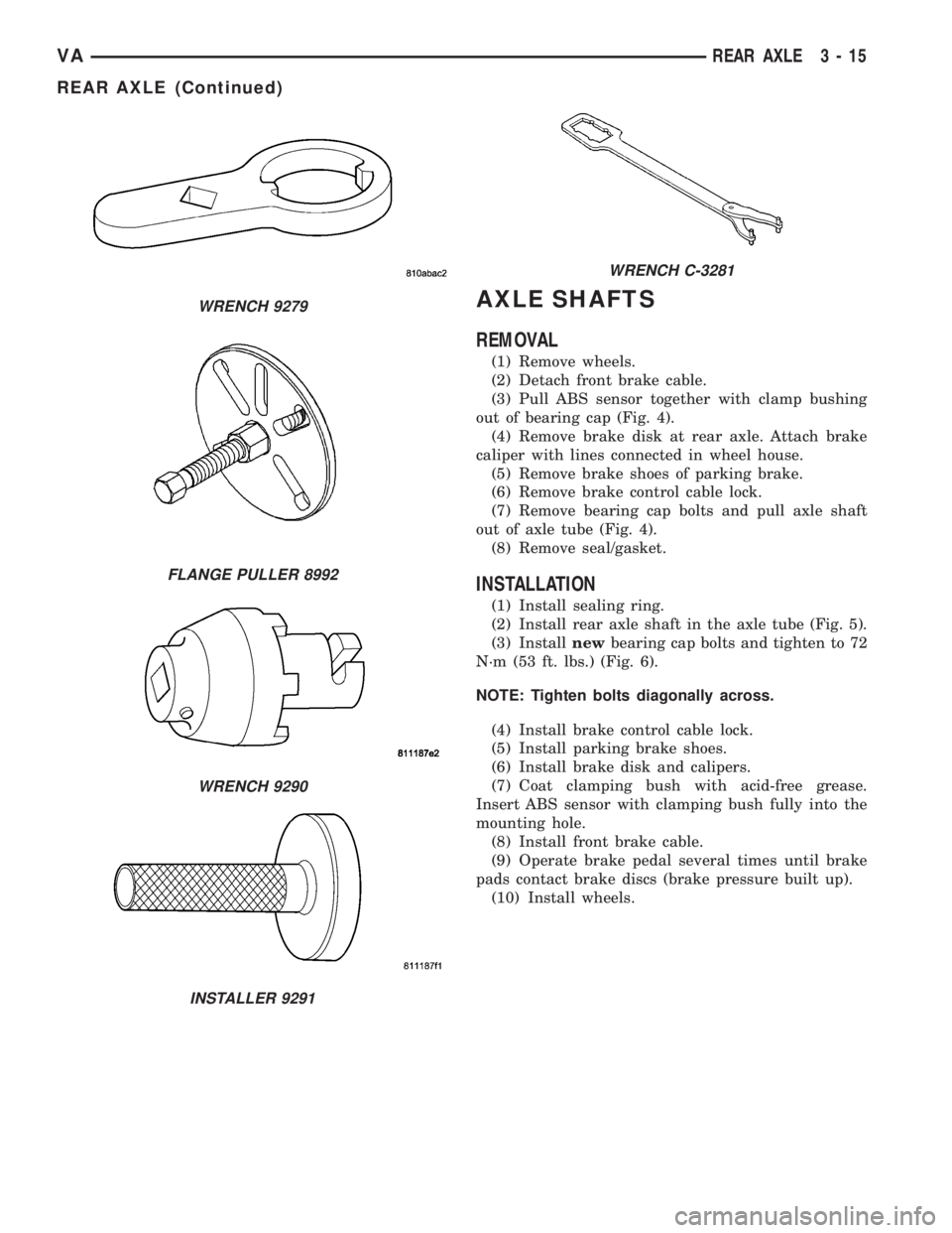
WRENCH 9279
FLANGE PULLER 8992
WRENCH 9290
INSTALLER 9291
WRENCH C-3281
VAREAR AXLE 3 - 15
REAR AXLE (Continued)
Page 56 of 1232
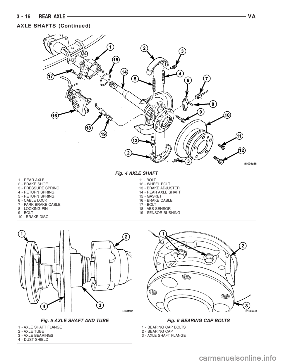
Fig. 4 AXLE SHAFT
1 - REAR AXLE 11 - BOLT
2 - BRAKE SHOE 12 - WHEEL BOLT
3 - PRESSURE SPRING 13 - BRAKE ADJUSTER
4 - RETURN SPRING 14 - REAR AXLE SHAFT
5 - RETURN SPRING 15 - GASKET
6 - CABLE LOCK 16 - BRAKE CABLE
7 - PARK BRAKE CABLE 17 - BOLT
8 - LOCKING PIN 18 - ABS SENSOR
9 - BOLT 19 - SENSOR BUSHING
10 - BRAKE DISC
Fig. 5 AXLE SHAFT AND TUBE
1 - AXLE SHAFT FLANGE
2 - AXLE TUBE
3 - AXLE BEARINGS
4 - DUST SHIELD
Fig. 6 BEARING CAP BOLTS
1 - BEARING CAP BOLTS
2 - BEARING CAP
3 - AXLE SHAFT FLANGE
3 - 16 REAR AXLEVA
AXLE SHAFTS (Continued)
Page 57 of 1232
AXLE BEARINGS/SEALS
REMOVAL
(1) Remove rear axle shaft.
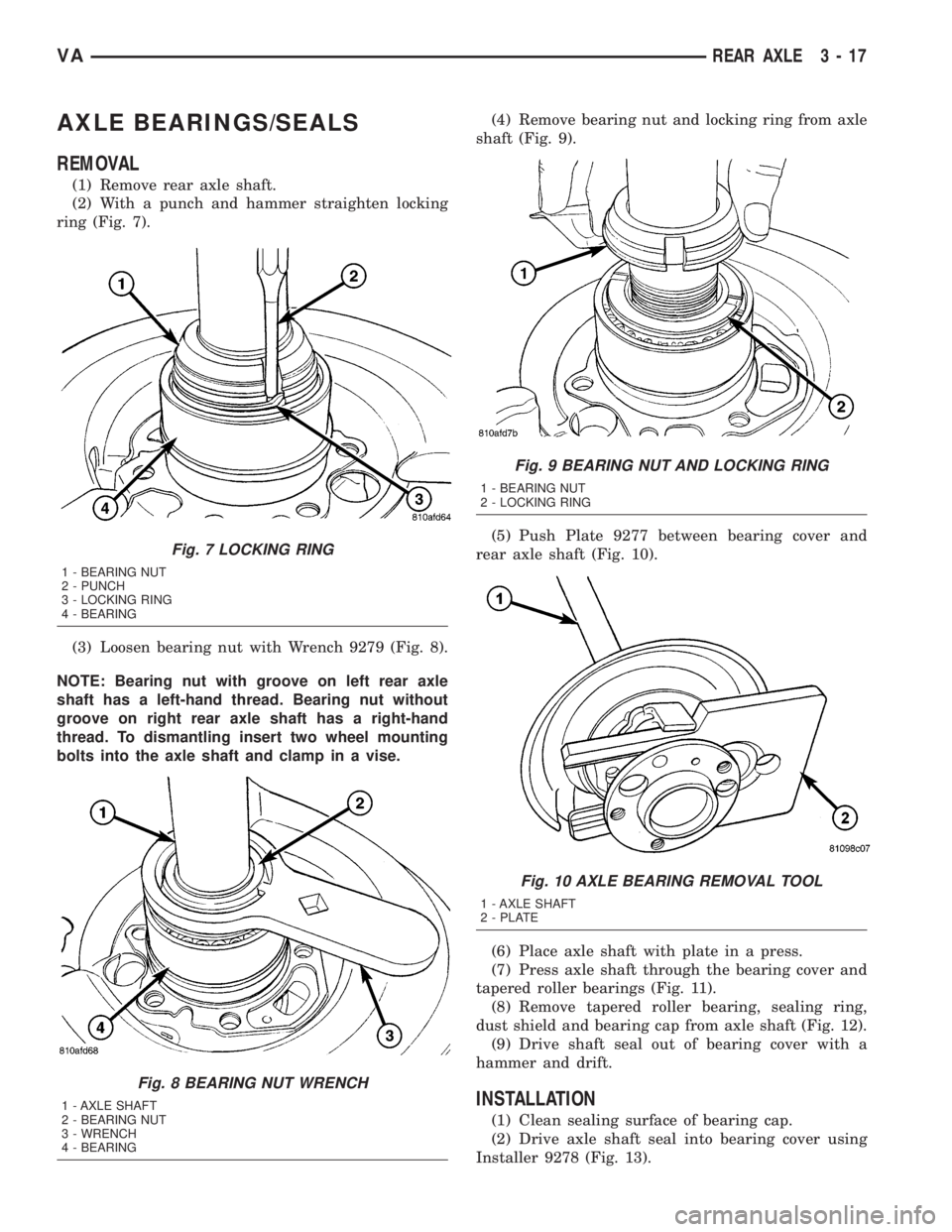
(2) With a punch and hammer straighten locking
ring (Fig. 7).
(3) Loosen bearing nut with Wrench 9279 (Fig. 8).
NOTE: Bearing nut with groove on left rear axle
shaft has a left-hand thread. Bearing nut without
groove on right rear axle shaft has a right-hand
thread. To dismantling insert two wheel mounting
bolts into the axle shaft and clamp in a vise.(4) Remove bearing nut and locking ring from axle
shaft (Fig. 9).
(5) Push Plate 9277 between bearing cover and
rear axle shaft (Fig. 10).
(6) Place axle shaft with plate in a press.
(7) Press axle shaft through the bearing cover and
tapered roller bearings (Fig. 11).
(8) Remove tapered roller bearing, sealing ring,
dust shield and bearing cap from axle shaft (Fig. 12).
(9) Drive shaft seal out of bearing cover with a
hammer and drift.
INSTALLATION
(1) Clean sealing surface of bearing cap.
(2) Drive axle shaft seal into bearing cover using
Installer 9278 (Fig. 13).
Fig. 7 LOCKING RING
1 - BEARING NUT
2 - PUNCH
3 - LOCKING RING
4 - BEARING
Fig. 8 BEARING NUT WRENCH
1 - AXLE SHAFT
2 - BEARING NUT
3 - WRENCH
4 - BEARING
Fig. 9 BEARING NUT AND LOCKING RING
1 - BEARING NUT
2 - LOCKING RING
Fig. 10 AXLE BEARING REMOVAL TOOL
1 - AXLE SHAFT
2 - PLATE
VAREAR AXLE 3 - 17
Page 75 of 1232
INSTALLATION - FRONT (DRW)
(1) Install the brake pads (Fig. 5).
(2) Install the wear indicator cable and the wear
indicator (Fig. 5). Tighten to 10 N´m (89 in. lbs.).
NOTE: Do not install the brake hose twisted and
ensure freedom of movement.
(3) Install the brake caliper to the brake caliper
adapter (Fig. 5). Tighten the guide bolt to 25 N´m
(221 in. lbs.)(M8 bolt) or Tighten the guide bolt to 30
N´m (265 in. lbs.)(M10 10.9 bolt).
(4) Bleed the brake system.
(5) Check the brake system for any leaks.
(6) Install the front wheels.
(7) Lower the vehicle.
INSTALLATION - REAR (16º WHEELS) (SRW)
(1) Install the brake pads (Fig. 6).
(2) Install the wear indicator cable and the wear
indicator (Fig. 6). Tighten to 10 N´m (89 in. lbs.).
NOTE: Do not install the brake hose twisted and
ensure freedom of movement.
(3) Install the brake caliper to brake caliper
adapter (Fig. 6). Tighten the guide pins to 25 N´m
(221 in. lbs.) for M8 bolt or 30 N´m (266 in. lbs.) for
M10 bolt.
(4) Install the retaining spring (Fig. 6).
(5) Install the rear wheels (Refer to 22 - TIRES/
WHEELS/WHEELS - INSTALLATION).
(6) Lower the vehicle.
INSTALLATION - REAR (16º WHEELS) (SRW)
(1) Install the brake pads (Fig. 7).
(2) Install the wear indicator cable and the wear
indicator (Fig. 7). Tighten to 10 N´m (89 in. lbs.).
NOTE: Do not install the brake hose twisted and
ensure freedom of movement.
(3) Install the brake caliper to brake caliper
adapter (Fig. 7). Tighten the guide pin to 30 N´m
(266 in. lbs.) for M10 bolt.
(4) Install the rear wheels (Refer to 22 - TIRES/
WHEELS/WHEELS - INSTALLATION).
(5) Lower the vehicle.
INSTALLATION - REAR (DRW)
(1) Install the brake pads (Fig. 8).
(2) Install the wear indicator cable and the wear
indicator (Fig. 8). Tighten to 10 N´m (89 in. lbs.).
NOTE: Do not install the brake hose twisted and
ensure freedom of movement.(3) Install the brake caliper to brake caliper
adapter (Fig. 8). Tighten the guide pins to 25 N´m
(221 in. lbs.) for M8 bolt or 30 N´m (266 in. lbs.) for
M10 10.9 bolt.
(4) Install the retaining spring (Fig. 8).
(5) Install the rear wheels (Refer to 22 - TIRES/
WHEELS/WHEELS - INSTALLATION).
(6) Lower the vehicle.
DISC BRAKE CALIPERS
REMOVAL
REMOVAL - FRONT (SRW)
(1) Unscrew the cap from the brake fluid reservoir.
(2) Raise and support the vehicle.
(3) Remove the front wheels (Refer to 22 - TIRES/
WHEELS/WHEELS - REMOVAL).
(4) Remove the wear indicator cable and the wear
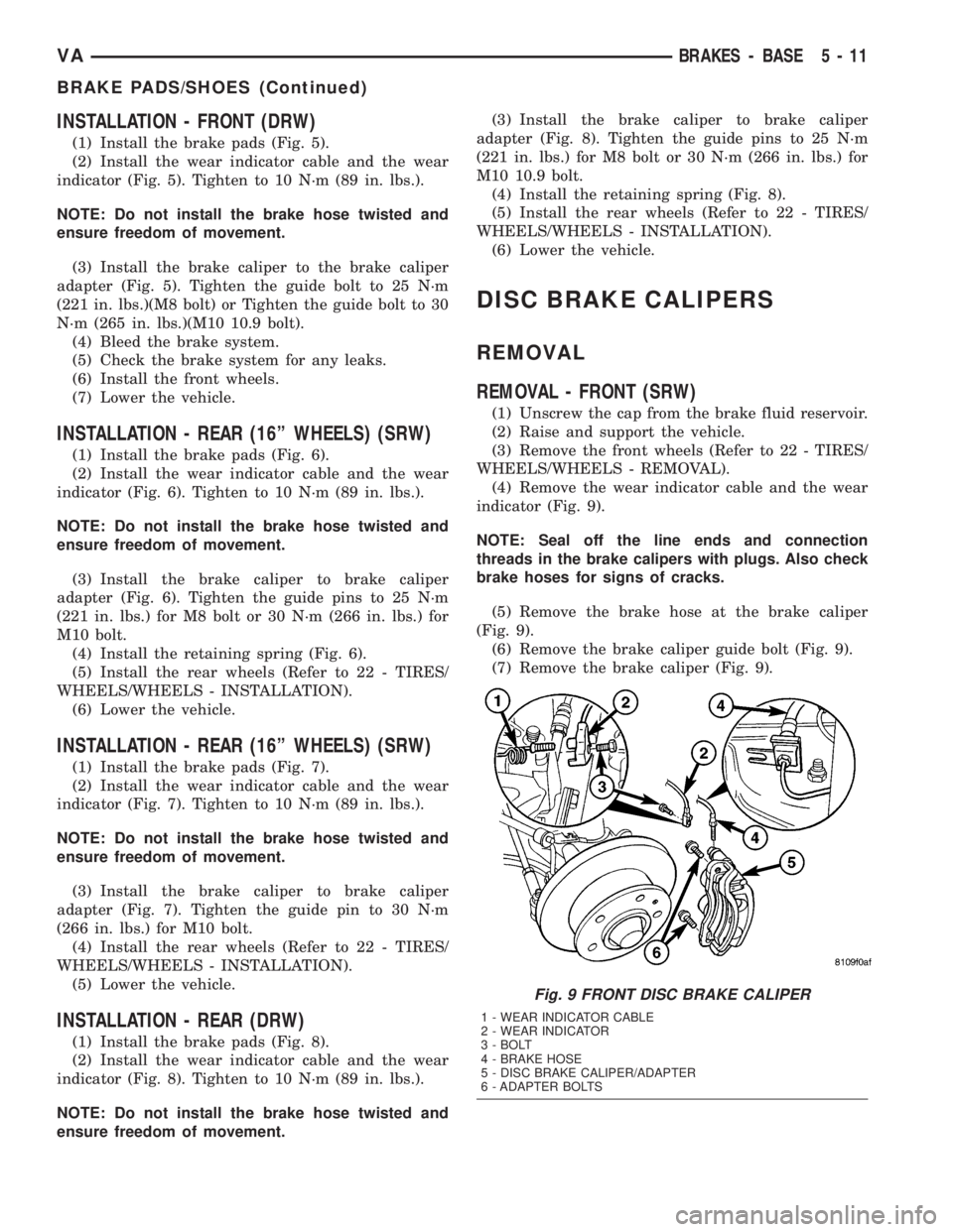
indicator (Fig. 9).
NOTE: Seal off the line ends and connection
threads in the brake calipers with plugs. Also check
brake hoses for signs of cracks.
(5) Remove the brake hose at the brake caliper
(Fig. 9).
(6) Remove the brake caliper guide bolt (Fig. 9).
(7) Remove the brake caliper (Fig. 9).
Fig. 9 FRONT DISC BRAKE CALIPER
1 - WEAR INDICATOR CABLE
2 - WEAR INDICATOR
3 - BOLT
4 - BRAKE HOSE
5 - DISC BRAKE CALIPER/ADAPTER
6 - ADAPTER BOLTS
VABRAKES - BASE 5 - 11
BRAKE PADS/SHOES (Continued)
Page 76 of 1232
REMOVAL - FRONT (DRW)
(1) Unscrew the cap from the brake fluid reservoir.
(2) Raise and support the vehicle.
(3) Remove the front wheels (Refer to 22 - TIRES/
WHEELS/WHEELS - REMOVAL).
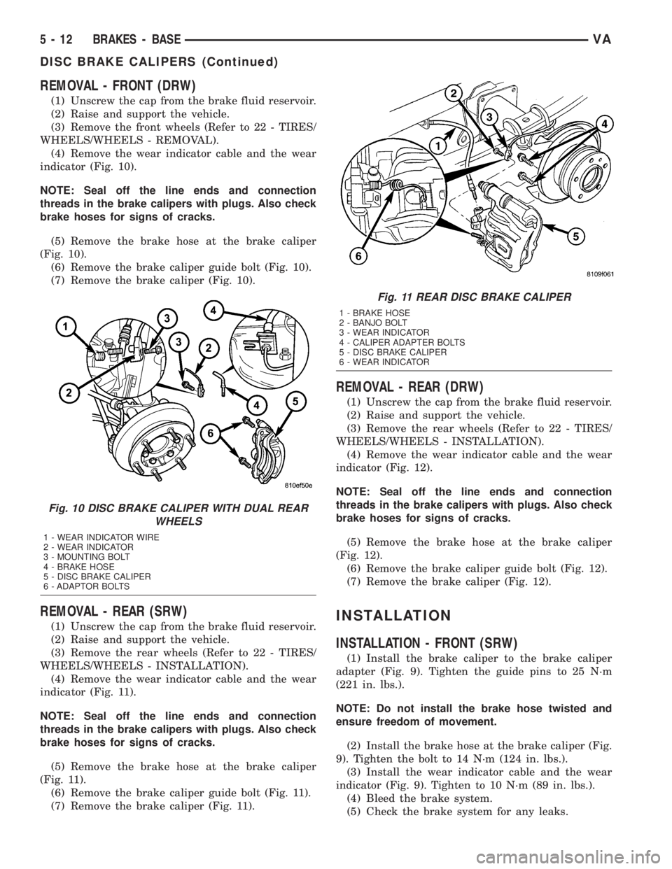
(4) Remove the wear indicator cable and the wear
indicator (Fig. 10).
NOTE: Seal off the line ends and connection
threads in the brake calipers with plugs. Also check
brake hoses for signs of cracks.
(5) Remove the brake hose at the brake caliper
(Fig. 10).
(6) Remove the brake caliper guide bolt (Fig. 10).
(7) Remove the brake caliper (Fig. 10).
REMOVAL - REAR (SRW)
(1) Unscrew the cap from the brake fluid reservoir.
(2) Raise and support the vehicle.
(3) Remove the rear wheels (Refer to 22 - TIRES/
WHEELS/WHEELS - INSTALLATION).
(4) Remove the wear indicator cable and the wear
indicator (Fig. 11).
NOTE: Seal off the line ends and connection
threads in the brake calipers with plugs. Also check
brake hoses for signs of cracks.
(5) Remove the brake hose at the brake caliper
(Fig. 11).
(6) Remove the brake caliper guide bolt (Fig. 11).
(7) Remove the brake caliper (Fig. 11).
REMOVAL - REAR (DRW)
(1) Unscrew the cap from the brake fluid reservoir.
(2) Raise and support the vehicle.
(3) Remove the rear wheels (Refer to 22 - TIRES/
WHEELS/WHEELS - INSTALLATION).
(4) Remove the wear indicator cable and the wear
indicator (Fig. 12).
NOTE: Seal off the line ends and connection
threads in the brake calipers with plugs. Also check
brake hoses for signs of cracks.
(5) Remove the brake hose at the brake caliper
(Fig. 12).
(6) Remove the brake caliper guide bolt (Fig. 12).
(7) Remove the brake caliper (Fig. 12).
INSTALLATION
INSTALLATION - FRONT (SRW)
(1) Install the brake caliper to the brake caliper
adapter (Fig. 9). Tighten the guide pins to 25 N´m
(221 in. lbs.).
NOTE: Do not install the brake hose twisted and
ensure freedom of movement.
(2) Install the brake hose at the brake caliper (Fig.
9). Tighten the bolt to 14 N´m (124 in. lbs.).
(3) Install the wear indicator cable and the wear
indicator (Fig. 9). Tighten to 10 N´m (89 in. lbs.).
(4) Bleed the brake system.
(5) Check the brake system for any leaks.
Fig. 10 DISC BRAKE CALIPER WITH DUAL REAR
WHEELS
1 - WEAR INDICATOR WIRE
2 - WEAR INDICATOR
3 - MOUNTING BOLT
4 - BRAKE HOSE
5 - DISC BRAKE CALIPER
6 - ADAPTOR BOLTS
Fig. 11 REAR DISC BRAKE CALIPER
1 - BRAKE HOSE
2 - BANJO BOLT
3 - WEAR INDICATOR
4 - CALIPER ADAPTER BOLTS
5 - DISC BRAKE CALIPER
6 - WEAR INDICATOR
5 - 12 BRAKES - BASEVA
DISC BRAKE CALIPERS (Continued)
Page 83 of 1232
INSTALLATION
(1) Install the bolts for the pedal bearing bracket
(Fig. 22). Tighten to 23 N´m (204 in. lbs.)
(2) Reconnect the plug connector for the stop lamp
switch (Fig. 22).
(3) Install the brake pedal and hook the spring
(Fig. 22).
(4) Install the retainer and pin for the brake pedal
(Fig. 22).
(5) Install the retainer and pin for the master cyl-
inder push rod (Fig. 22).
(6) Install the master cylinder (Refer to 5 -
BRAKES/HYDRAULIC/MECHANICAL/MASTER
CYLINDER - INSTALLATION).
POWER BRAKE BOOSTER
DESCRIPTION
All models use a tandem diaphragm, power brake
booster.
NOTE: The power brake booster is not a repairable
component. The booster must be replaced as an
assembly if diagnosis indicates a malfunction has
occurred.
OPERATION
The booster unit consists of a single housing
divided into two by a tandem diaphragm. The outer
edge of the diaphragm is secured to the housing. The
booster push rod, which connects the booster to the
brake pedal and master cylinder, is attached to the
center of the diaphragm. A check valve is used in the
booster outlet connected to the engine intake mani-
fold. Power assist is generated by utilizing a combi-
nation of vacuum and atmospheric pressure to boost
brake assist.
REMOVAL
(1) Using a suction gun remove as much brake
fluid from the reservoir as possible.
(2) Disconnect the brake level switch electrical
connector.
(3) Remove the brake lines from the master cylin-
derSeal off the ends and bore holes with plugs.
(4) Remove the master cylinder from the booster.
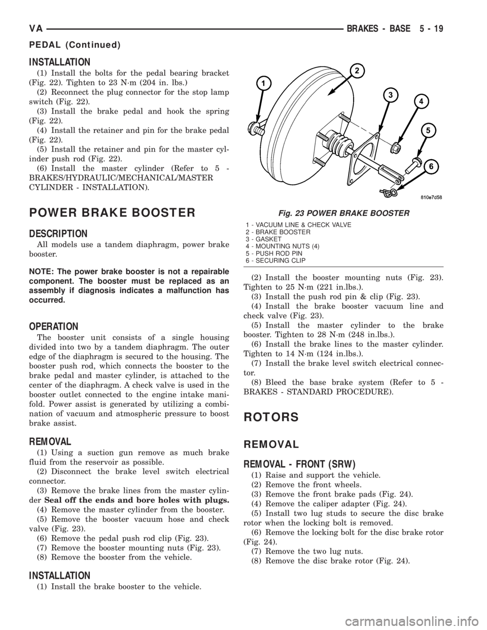
(5) Remove the booster vacuum hose and check
valve (Fig. 23).
(6) Remove the pedal push rod clip (Fig. 23).
(7) Remove the booster mounting nuts (Fig. 23).
(8) Remove the booster from the vehicle.
INSTALLATION
(1) Install the brake booster to the vehicle.(2) Install the booster mounting nuts (Fig. 23).
Tighten to 25 N´m (221 in.lbs.).
(3) Install the push rod pin & clip (Fig. 23).
(4) Install the brake booster vacuum line and
check valve (Fig. 23).
(5) Install the master cylinder to the brake
booster. Tighten to 28 N´m (248 in.lbs.).
(6) Install the brake lines to the master cylinder.
Tighten to 14 N´m (124 in.lbs.).
(7) Install the brake level switch electrical connec-
tor.
(8) Bleed the base brake system (Refer to 5 -
BRAKES - STANDARD PROCEDURE).
ROTORS
REMOVAL
REMOVAL - FRONT (SRW)
(1) Raise and support the vehicle.
(2) Remove the front wheels.
(3) Remove the front brake pads (Fig. 24).
(4) Remove the caliper adapter (Fig. 24).
(5) Install two lug studs to secure the disc brake
rotor when the locking bolt is removed.
(6) Remove the locking bolt for the disc brake rotor
(Fig. 24).
(7) Remove the two lug nuts.
(8) Remove the disc brake rotor (Fig. 24).
Fig. 23 POWER BRAKE BOOSTER
1 - VACUUM LINE & CHECK VALVE
2 - BRAKE BOOSTER
3 - GASKET
4 - MOUNTING NUTS (4)
5 - PUSH ROD PIN
6 - SECURING CLIP
VABRAKES - BASE 5 - 19
PEDAL (Continued)
Page 89 of 1232
(5) Adjust the parking park.
(6) Lower the vehicle.
INSTALLATION - REAR
NOTE: Route the park brake cable free of tension
and the risk of chafing.
(1) Install the hand brake cable to the anchor
plate (Fig. 31).
(2) Install the park brake cable lock (Fig. 31).
(3) Install all connections on the hardware cable
(Fig. 31).
(4) Install the park brake cables to the shoe (Fig.
31).
(5) Install the park brake shoes.
(6) Install the rear wheels.
(7) Adjust the park brakes.
(8) Lower the vehicle.
ADJUSTMENTS
ADJUSTMENT - PARKING BRAKE CABLES
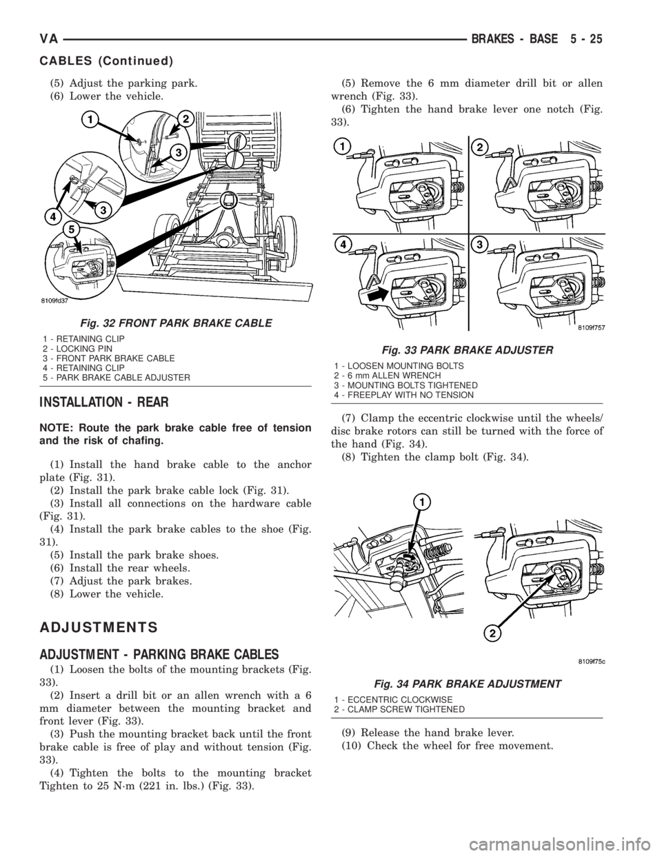
(1) Loosen the bolts of the mounting brackets (Fig.
33).
(2) Insert a drill bit or an allen wrench with a 6
mm diameter between the mounting bracket and
front lever (Fig. 33).
(3) Push the mounting bracket back until the front
brake cable is free of play and without tension (Fig.
33).
(4) Tighten the bolts to the mounting bracket
Tighten to 25 N´m (221 in. lbs.) (Fig. 33).(5) Remove the 6 mm diameter drill bit or allen
wrench (Fig. 33).
(6) Tighten the hand brake lever one notch (Fig.
33).
(7) Clamp the eccentric clockwise until the wheels/
disc brake rotors can still be turned with the force of
the hand (Fig. 34).
(8) Tighten the clamp bolt (Fig. 34).
(9) Release the hand brake lever.
(10) Check the wheel for free movement.
Fig. 32 FRONT PARK BRAKE CABLE
1 - RETAINING CLIP
2 - LOCKING PIN
3 - FRONT PARK BRAKE CABLE
4 - RETAINING CLIP
5 - PARK BRAKE CABLE ADJUSTER
Fig. 33 PARK BRAKE ADJUSTER
1 - LOOSEN MOUNTING BOLTS
2-6mmALLEN WRENCH
3 - MOUNTING BOLTS TIGHTENED
4 - FREEPLAY WITH NO TENSION
Fig. 34 PARK BRAKE ADJUSTMENT
1 - ECCENTRIC CLOCKWISE
2 - CLAMP SCREW TIGHTENED
VABRAKES - BASE 5 - 25
CABLES (Continued)