2005 MERCEDES-BENZ SPRINTER plugs
[x] Cancel search: plugsPage 1110 of 1232
Cargo Van
(1) Remove bolts and remove tie down rings, if
equipped.
(2) Remove rivets and remove paneling
INSTALLATION
Passenger Van
(1) Position trim panels and seat push-pin fasten-
ers fully.
(2) Install d-pillar trim, if necessary. (Refer to 23 -
BODY/INTERIOR/D-PILLAR TRIM - INSTALLA-
TION)
(3) Install seats, if necessary. (Refer to 23 - BODY/
SEATS/SEAT - INSTALLATION)
Cargo Van
(1) Install paneling and replace rivets.
(2) Install tie down rings and bolts, if equipped.
REAR VIEW MIRROR
REMOVAL
(1) Slide mirror off support bracket.
INSTALLATION
INSTALLATION
(1) Install the support bracket if necessary. (Refer
to 23 - BODY/INTERIOR/REAR VIEW MIRROR -
INSTALLATION - SUPPORT BRACKET)
(2) Slide mirror onto support bracket fully.
INSTALLATION - REAR VIEW MIRROR
SUPPORT BRACKET
(1) Mark the position for the mirror bracket on the
outside of the windshield glass with a wax pencil.
(2) Clean the bracket contact area on the glass.
Use a mild powdered cleanser on a cloth saturated
with isopropyl (rubbing) alcohol. Finally, clean the
glass with a paper towel dampened with alcohol.
(3) Sand the surface on the support bracket with
fine grit-sandpaper. Wipe the bracket surface clean
with a paper towel.
(4) Apply accelerator to the surface on the bracket
according to the following instructions:
(a) Crush the vial to saturate the felt applicator.
(b) Remove the paper sleeve.
(c) Apply accelerator to the contact surface on
the bracket.
(d) Allow the accelerator to dry for five minutes.
(e) Do not touch the bracket contact surface
after the accelerator has been applied.(5) Apply adhesive accelerator to the bracket con-
tact surface on the windshield glass. Allow the accel-
erator to dry for one minute. Do not touch the glass
contact surface after the accelerator has been
applied.
(6) Install the bracket according to the following
instructions:
(a) Apply one drop of adhesive at the center of
the bracket contact-surface on the windshield
glass.
(b) Apply an even coat of adhesive to the contact
surface on the bracket.
(c) Align the bracket with the marked position
on the windshield glass.
(d) Press and hold the bracket in place for at
least one minute.
NOTE: Verify that the mirror support bracket is cor-
rectly aligned, because the adhesive will cure rap-
idly.
(7) Allow the adhesive to cure for 8-10 minutes.
Remove any excess adhesive with an alcohol-damp-
ened cloth.
(8) Allow the adhesive to cure for an additional
8-10 minutes before installing the mirror.
STEPWELL SCUFF PADS
REMOVAL
(1) Remove screws and remove seat bracket if nec-
essary.
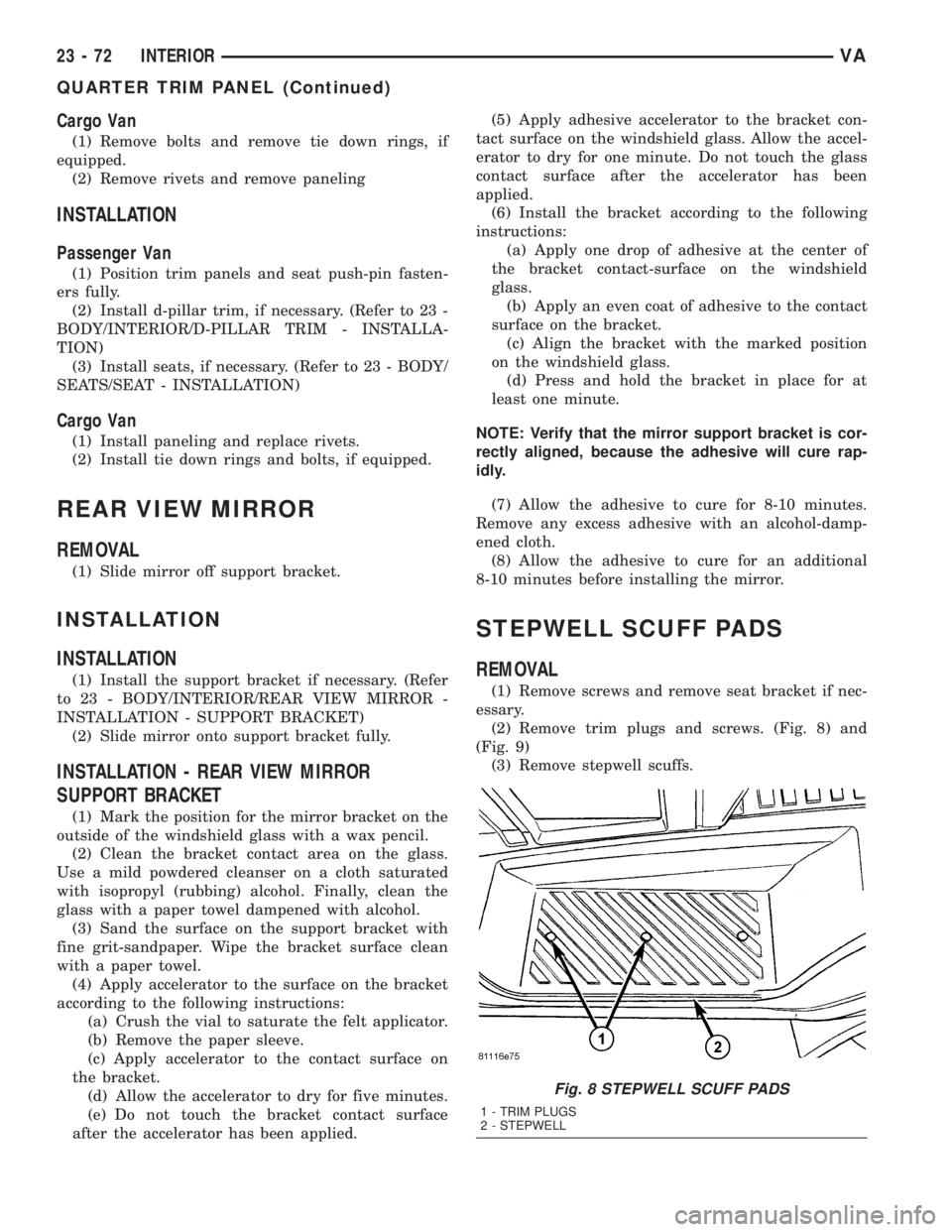
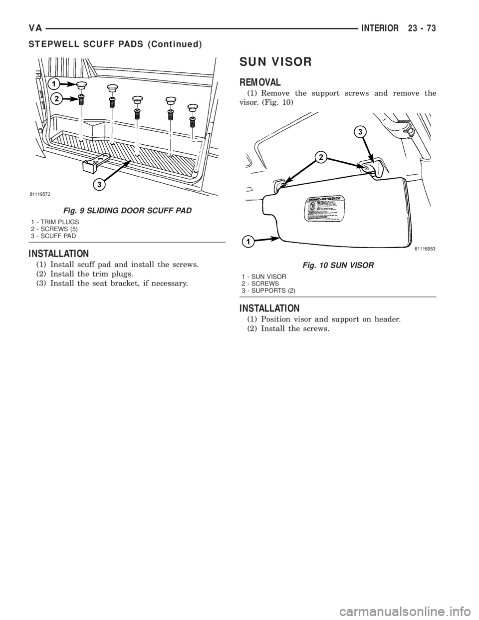
(2) Remove trim plugs and screws. (Fig. 8) and
(Fig. 9)
(3) Remove stepwell scuffs.
Fig. 8 STEPWELL SCUFF PADS
1 - TRIM PLUGS
2 - STEPWELL
23 - 72 INTERIORVA
QUARTER TRIM PANEL (Continued)
Page 1111 of 1232
INSTALLATION
(1) Install scuff pad and install the screws.
(2) Install the trim plugs.
(3) Install the seat bracket, if necessary.
SUN VISOR
REMOVAL
(1) Remove the support screws and remove the
visor. (Fig. 10)
INSTALLATION
(1) Position visor and support on header.
(2) Install the screws.
Fig. 9 SLIDING DOOR SCUFF PAD
1 - TRIM PLUGS
2 - SCREWS (5)
3 - SCUFF PAD
Fig. 10 SUN VISOR
1 - SUN VISOR
2 - SCREWS
3 - SUPPORTS (2)
VAINTERIOR 23 - 73
STEPWELL SCUFF PADS (Continued)
Page 1156 of 1232
(9) Remove the rear evaporator panel from the
vehicle.
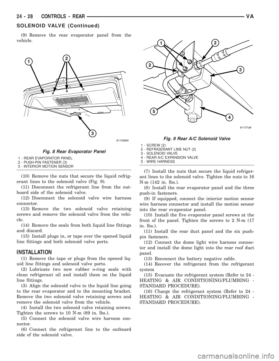
(10) Remove the nuts that secure the liquid refrig-
erant lines to the solenoid valve (Fig. 9).
(11) Disconnect the refrigerant line from the out-
board side of the solenoid valve.
(12) Disconnect the solenoid valve wire harness
connector.
(13) Remove the two solenoid valve retaining
screws and remove the solenoid valve from the vehi-
cle.
(14) Remove the seals from both liquid line fittings
and discard.
(15) Install plugs in, or tape over the opened liquid
line fittings and both solenoid valve ports.
INSTALLATION
(1) Remove the tape or plugs from the opened liq-
uid line fittings and solenoid valve ports.
(2) Lubricate two new rubber o-ring seals with
clean refrigerant oil and install them on the liquid
line fittings.
(3) Align the solenoid valve to the liquid line going
to the rear evaporator and to the mounting bracket.
Remove the two solenoid valve retaining screws and
remove the solenoid valve from the vehicle.
(4) Install the two solenoid valve retaining screws.
Tighten the screws to 10 N´m (89 in. lbs.).
(5) Connect the solenoid valve wire harness con-
nector.
(6) Connect the refrigerant line to the outboard
side of the solenoid valve.(7) Install the nuts that secure the liquid refriger-
ant lines to the solenoid valve. Tighten the nuts to 16
N´m (142 in. lbs.).
(8) Install the rear evaporator panel and the three
push-in fasteners.
(9) If equipped, connect the interior motion sensor
wire harness connector and install the motion sensor
into the rear evaporator panel.
(10) Install the five evaporator panel screws at the
front of the panel. Tighten the screws to 2 N´m (17
in. lbs.).
(11) Install the rear duct panel and the six push-
pin fasteners.
(12) Connect the dome light wire harness connec-
tor and install the dome light into the rear roof duct
panel.
(13) Reconnect the battery negative cable.
(14) Recover the refrigerant from the refrigerant
system
(15) Evacuate the refrigerant system (Refer to 24 -
HEATING & AIR CONDITIONING/PLUMBING -
STANDARD PROCEDURE).
(16) Charge the refrigerant system (Refer to 24 -
HEATING & AIR CONDITIONING/PLUMBING -
STANDARD PROCEDURE).
Fig. 8 Rear Evaporator Panel
1 - REAR EVAPORATOR PANEL
2 - PUSH-PIN FASTENER (3)
3 - INTERIOR MOTION SENSOR
Fig. 9 Rear A/C Solenoid Valve
1 - SCREW (2)
2 - REFRIGERANT LINE NUT (2)
3 - SOLENOID VALVE
4 - REAR A/C EXPANSION VALVE
5 - WIRE HARNESS
24 - 28 CONTROLS - REARVA
SOLENOID VALVE (Continued)
Page 1163 of 1232
(9) Disconnect the wire harness connector from the
blower motor (Refer to 24 - HEATING & AIR CON-
DITIONING/DISTRIBUTION/BLOWER MOTOR -
REMOVAL).
(10) Remove the nuts and washers that secure the
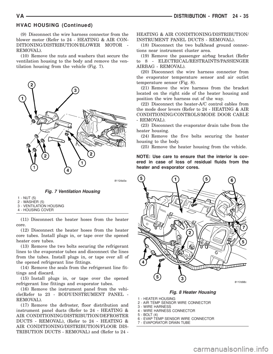
ventilation housing to the body and remove the ven-
tilation housing from the vehicle (Fig. 7).
(11) Disconnect the heater hoses from the heater
core.
(12) Disconnect the heater hoses from the heater
core tubes. Install plugs in, or tape over the opened
heater core tubes.
(13) Remove the two bolts securing the refrigerant
lines to the evaporator tubes and disconnect the lines
from the tubes. Install plugs in, or tape over all of
the opened refrigerant line fittings.
(14) Remove the seals from the refrigerant line fit-
tings and discard.
(15) Install plugs in, or tape over the opened
refrigerant line fittings and evaporator tubes.
(16) Remove the instrument panel from the vehi-
cle(Refer to 23 - BODY/INSTRUMENT PANEL -
REMOVAL).
(17) Remove the defroster, floor distribution and
instrument panel ducts (Refer to 24 - HEATING &
AIR CONDITIONING/DISTRIBUTION/DEFROSTER
DUCTS - REMOVAL), (Refer to 24 - HEATING &
AIR CONDITIONING/DISTRIBUTION/FLOOR DIS-
TRIBUTION DUCTS - REMOVAL) and (Refer to 24 -HEATING & AIR CONDITIONING/DISTRIBUTION/
INSTRUMENT PANEL DUCTS - REMOVAL).
(18) Disconnect the two bulkhead ground connec-
tions near instrument cluster area.
(19) Remove the passenger airbag bracket (Refer
to 8 - ELECTRICAL/RESTRAINTS/PASSENGER
AIRBAG - REMOVAL).
(20) Disconnect the wire harness connector from
the evaporator temperature sensor and air outlet
temperature sensor (Fig. 8).
(21) Remove the wire harness from the bracket
located on the right side of the heater housing and
position the wire harness out of the way.
(22) Disconnect the heater-A/C control cables from
the mode door levers (Refer to 24 - HEATING & AIR
CONDITIONING/CONTROLS/MODE DOOR CABLE
- REMOVAL).
(23) Disconnect the evaporator drain tube from the
heater housing.
(24) Remove the five bolts securing the heater
housing to the body.
(25) Remove the heater housing from the vehicle.
NOTE: Use care to ensure that the interior is cov-
ered in case of loss of residual fluids from the
heater and evaporator cores.
Fig. 7 Ventilation Housing
1 - NUT (5)
2 - WASHER (5)
3 - VENTILATION HOUSING
4 - HOUSING COVER
Fig. 8 Heater Housing
1 - HEATER HOUSING
2 - AIR TEMP SENSOR WIRE CONNECTOR
3 - WIRE HARNESS
4 - WIRE HARNESS CONNECTOR
5 - BOLT (4)
6 - EVAP TEMP SENSOR WIRE CONNECTOR
7 - EVAPORATOR DRAIN TUBE
VADISTRIBUTION - FRONT 24 - 35
HVAC HOUSING (Continued)
Page 1164 of 1232
DISASSEMBLY
(1) Remove the heater and ventilation housings
from the vehicle (Refer to 24 - HEATING & AIR
CONDITIONING/DISTRIBUTION/HVAC HOUSING
- REMOVAL).
(2) Place the heater housing in the upright posi-
tion on a work bench, making allowance for leakage
of fluids.
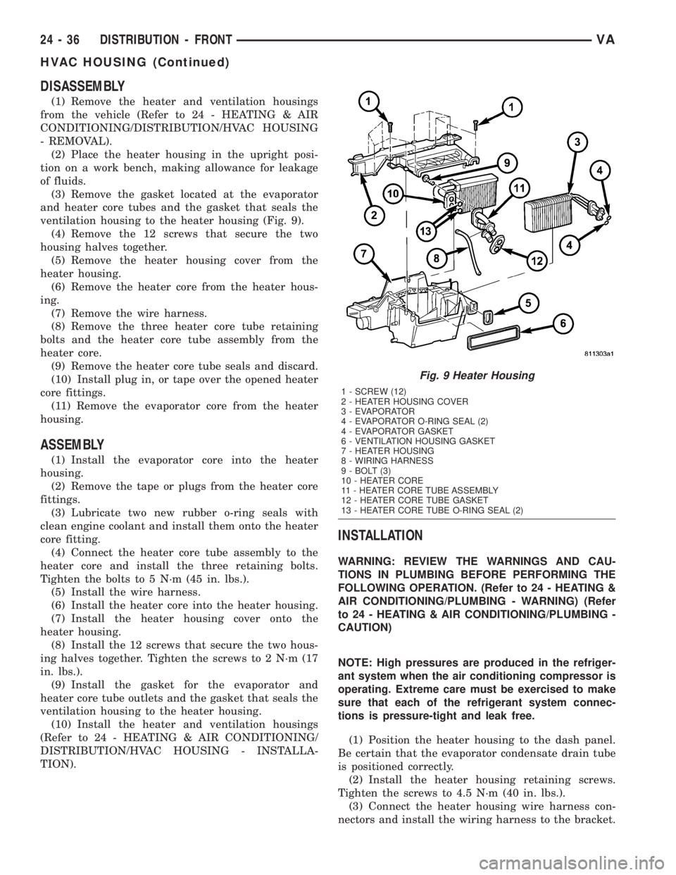
(3) Remove the gasket located at the evaporator
and heater core tubes and the gasket that seals the
ventilation housing to the heater housing (Fig. 9).
(4) Remove the 12 screws that secure the two
housing halves together.
(5) Remove the heater housing cover from the
heater housing.
(6) Remove the heater core from the heater hous-
ing.
(7) Remove the wire harness.
(8) Remove the three heater core tube retaining
bolts and the heater core tube assembly from the
heater core.
(9) Remove the heater core tube seals and discard.
(10) Install plug in, or tape over the opened heater
core fittings.
(11) Remove the evaporator core from the heater
housing.
ASSEMBLY
(1) Install the evaporator core into the heater
housing.
(2) Remove the tape or plugs from the heater core
fittings.
(3) Lubricate two new rubber o-ring seals with
clean engine coolant and install them onto the heater
core fitting.
(4) Connect the heater core tube assembly to the
heater core and install the three retaining bolts.
Tighten the bolts to 5 N´m (45 in. lbs.).
(5) Install the wire harness.
(6) Install the heater core into the heater housing.
(7) Install the heater housing cover onto the
heater housing.
(8) Install the 12 screws that secure the two hous-
ing halves together. Tighten the screws to 2 N´m (17
in. lbs.).
(9) Install the gasket for the evaporator and
heater core tube outlets and the gasket that seals the
ventilation housing to the heater housing.
(10) Install the heater and ventilation housings
(Refer to 24 - HEATING & AIR CONDITIONING/
DISTRIBUTION/HVAC HOUSING - INSTALLA-
TION).
INSTALLATION
WARNING: REVIEW THE WARNINGS AND CAU-
TIONS IN PLUMBING BEFORE PERFORMING THE
FOLLOWING OPERATION. (Refer to 24 - HEATING &
AIR CONDITIONING/PLUMBING - WARNING) (Refer
to 24 - HEATING & AIR CONDITIONING/PLUMBING -
CAUTION)
NOTE: High pressures are produced in the refriger-
ant system when the air conditioning compressor is
operating. Extreme care must be exercised to make
sure that each of the refrigerant system connec-
tions is pressure-tight and leak free.
(1) Position the heater housing to the dash panel.
Be certain that the evaporator condensate drain tube
is positioned correctly.
(2) Install the heater housing retaining screws.
Tighten the screws to 4.5 N´m (40 in. lbs.).
(3) Connect the heater housing wire harness con-
nectors and install the wiring harness to the bracket.
Fig. 9 Heater Housing
1 - SCREW (12)
2 - HEATER HOUSING COVER
3 - EVAPORATOR
4 - EVAPORATOR O-RING SEAL (2)
4 - EVAPORATOR GASKET
6 - VENTILATION HOUSING GASKET
7 - HEATER HOUSING
8 - WIRING HARNESS
9 - BOLT (3)
10 - HEATER CORE
11 - HEATER CORE TUBE ASSEMBLY
12 - HEATER CORE TUBE GASKET
13 - HEATER CORE TUBE O-RING SEAL (2)
24 - 36 DISTRIBUTION - FRONTVA
HVAC HOUSING (Continued)
Page 1169 of 1232
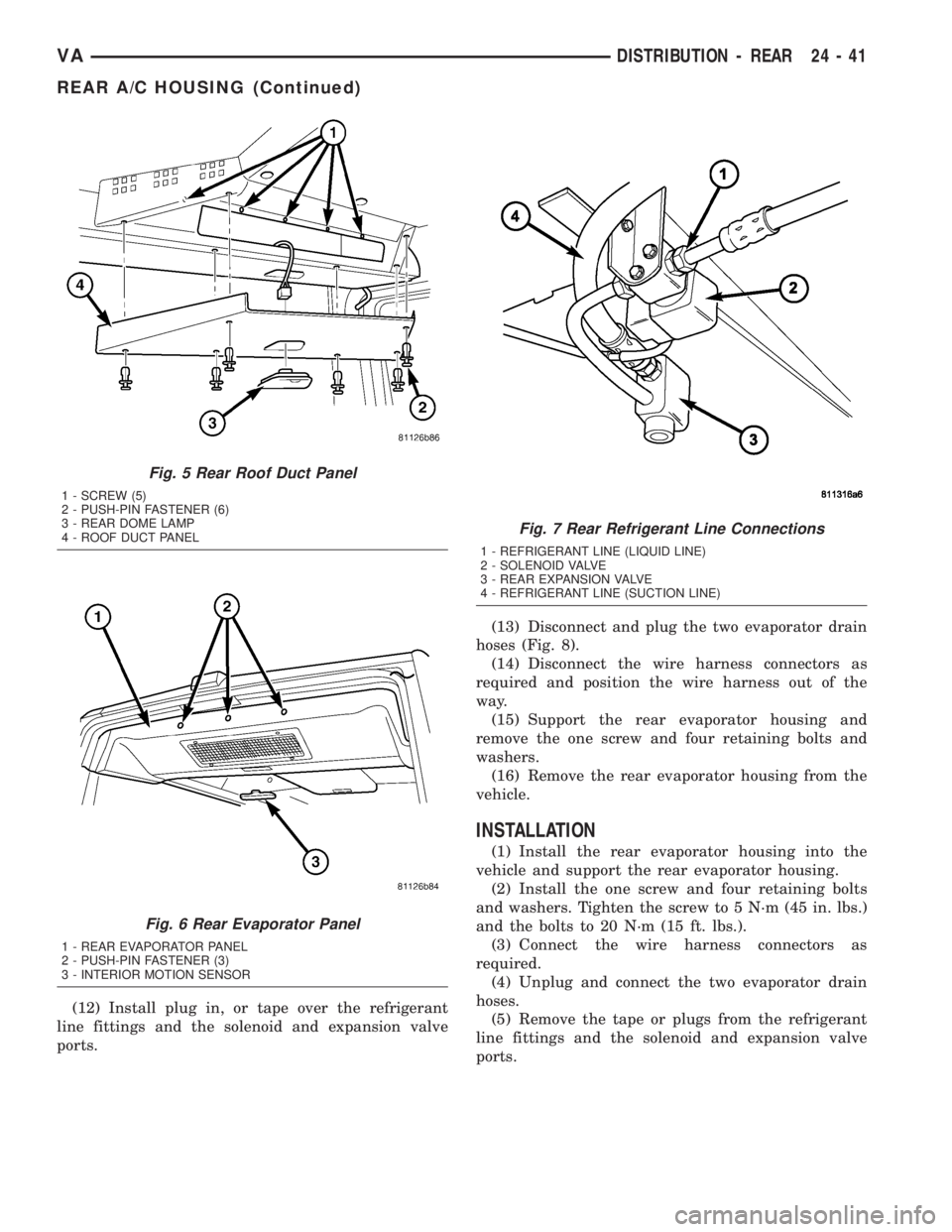
(12) Install plug in, or tape over the refrigerant
line fittings and the solenoid and expansion valve
ports.(13) Disconnect and plug the two evaporator drain
hoses (Fig. 8).
(14) Disconnect the wire harness connectors as
required and position the wire harness out of the
way.
(15) Support the rear evaporator housing and
remove the one screw and four retaining bolts and
washers.
(16) Remove the rear evaporator housing from the
vehicle.
INSTALLATION
(1) Install the rear evaporator housing into the
vehicle and support the rear evaporator housing.
(2) Install the one screw and four retaining bolts
and washers. Tighten the screw to 5 N´m (45 in. lbs.)
and the bolts to 20 N´m (15 ft. lbs.).
(3) Connect the wire harness connectors as
required.
(4) Unplug and connect the two evaporator drain
hoses.
(5) Remove the tape or plugs from the refrigerant
line fittings and the solenoid and expansion valve
ports.
Fig. 5 Rear Roof Duct Panel
1 - SCREW (5)
2 - PUSH-PIN FASTENER (6)
3 - REAR DOME LAMP
4 - ROOF DUCT PANEL
Fig. 6 Rear Evaporator Panel
1 - REAR EVAPORATOR PANEL
2 - PUSH-PIN FASTENER (3)
3 - INTERIOR MOTION SENSOR
Fig. 7 Rear Refrigerant Line Connections
1 - REFRIGERANT LINE (LIQUID LINE)
2 - SOLENOID VALVE
3 - REAR EXPANSION VALVE
4 - REFRIGERANT LINE (SUCTION LINE)
VADISTRIBUTION - REAR 24 - 41
REAR A/C HOUSING (Continued)
Page 1178 of 1232
Drive belts are speed sensitive. At different engine
speeds and depending upon belt tension, belts can
develop noises that are mistaken for a compressor
noise. Improper belt tension can cause a misleading
noise when the compressor clutch is engaged, which
may not occur when the compressor clutch is disen-
gaged. Check the serpentine drive belt condition and
tension as described in Cooling before beginning this
procedure.
(1) Select a quiet area for testing. Duplicate the
complaint conditions as much as possible. Switch the
compressor on and off several times to clearly iden-
tify the compressor noise. Listen to the compressor
while the clutch is engaged and disengaged. Probe
the compressor with an engine stethoscope or a long
screwdriver with the handle held to your ear to bet-
ter localize the source of the noise.
(2) Loosen all of the compressor mounting hard-
ware and retighten. Tighten the compressor clutch
mounting nut. Be certain that the clutch coil is
mounted securely to the compressor, and that the
clutch plate and pulley are properly aligned and have
the correct air gap. (Refer to 24 - HEATING & AIR
CONDITIONING/CONTROLS/A/C COMPRESSOR
CLUTCH - INSTALLATION)
(3) To duplicate a high-ambient temperature condi-
tion (high head pressure), restrict the air flow
through the condenser. Install a manifold gauge set
to be certain that the discharge pressure does not
exceed 2760 kPa (400 psi).
(4) Check the refrigerant system plumbing for
incorrect routing, rubbing or interference, which can
cause unusual noises. Also check the refrigerant lines
for kinks or sharp bends that will restrict refrigerant
flow, which can cause noises. (Refer to 24 - HEAT-
ING & AIR CONDITIONING/PLUMBING - CAU-
TION - REFRIGERANT HOSES/LINES/TUBES
PRECAUTIONS)
(5) If the noise is from opening and closing of the
high pressure relief valve, reclaim, evacuate, and
recharge the refrigerant system. (Refer to 24 - HEAT-
ING & AIR CONDITIONING/PLUMBING - STAN-
DARD PROCEDURE - REFRIGERANT RECOVERY)
(Refer to 24 - HEATING & AIR CONDITIONING/
PLUMBING - STANDARD PROCEDURE - REFRIG-
ERANT SYSTEM EVACUATE) (Refer to 24 -
HEATING & AIR CONDITIONING/PLUMBING -
STANDARD PROCEDURE - REFRIGERANT SYS-
TEM CHARGE)If the high pressure relief valve still
does not seat properly, replace the a/c compressor.
(Refer to 24 - HEATING & AIR CONDITIONING/
PLUMBING/A/C COMPRESSOR - REMOVAL)
(6) If the noise is from liquid slugging on the suc-
tion line, check the refrigerant oil level and the
refrigerant system charge. (Refer to 24 - HEATING
& AIR CONDITIONING/PLUMBING/REFRIGER-ANT OIL - STANDARD PROCEDURE) (Refer to 24 -
HEATING & AIR CONDITIONING/PLUMBING -
SPECIFICATIONS - CHARGE CAPACITY).
(7) If the noise continues, replace the compressor
and repeat Step 1.
REMOVAL
WARNING: REVIEW THE WARNINGS AND CAU-
TIONS IN THE FRONT OF THIS SECTION BEFORE
PERFORMING THE FOLLOWING OPERATION (Refer
to 24 - HEATING & AIR CONDITIONING/PLUMBING -
WARNING) and (Refer to 24 - HEATING & AIR CON-
DITIONING/PLUMBING - CAUTION).
(1) Disconnect the negative battery cable.
(2) Recover the refrigerant from the refrigerant
system (Refer to 24 - HEATING & AIR CONDITION-
ING/PLUMBING - STANDARD PROCEDURE -
REFRIGERANT RECOVERY).
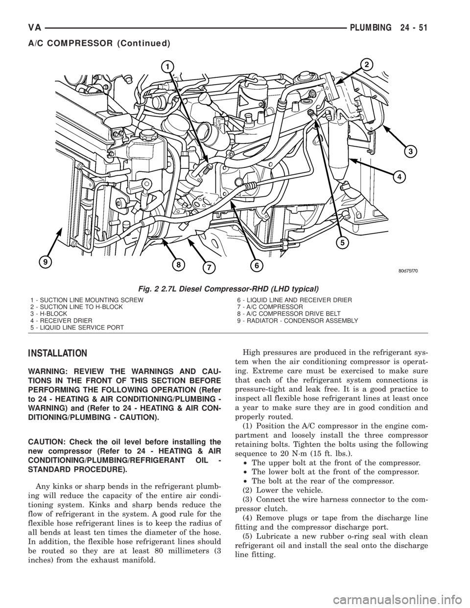
(3) Remove the accessory drive belt from the com-
pressor clutch (Fig. 2).
(4) Remove the bolt that secures the suction line
fitting to the top of the compressor.
(5) Disconnect the suction line fitting from the
compressor suction port.
(6) Remove the seal from the suction line fitting
and discard.
(7) Install plugs in, or tape over the opened suc-
tion line fitting and the compressor suction port.
(8) Remove the bolt that secures the discharge line
fitting to the top of the compressor.
(9) Disconnect the discharge line fitting from the
compressor discharge port.
(10) Remove the seal from the discharge line fit-
ting and discard.
(11) Install plugs in, or tape over the opened dis-
charge line fitting and the compressor discharge port.
(12) Disconnect the engine wire harness connector
for the compressor clutch coil from the coil pigtail
wire connector on the top of the compressor.
(13) Raise the vehicle on a hoist.
(14) Support the compressor and remove the three
compressor mounting bolts.
(15) Remove the compressor from the engine com-
partment.
NOTE: If a replacement compressor is being
installed, be certain to drain and measure the refrig-
erant oil contained in the removed compressor.
This will determine how much oil the replacement
compressor must contain before it is installed
(Refer to 24 - HEATING & AIR CONDITIONING/
PLUMBING/REFRIGERANT OIL - STANDARD PRO-
CEDURE).
24 - 50 PLUMBINGVA
A/C COMPRESSOR (Continued)
Page 1179 of 1232
INSTALLATION
WARNING: REVIEW THE WARNINGS AND CAU-
TIONS IN THE FRONT OF THIS SECTION BEFORE
PERFORMING THE FOLLOWING OPERATION (Refer
to 24 - HEATING & AIR CONDITIONING/PLUMBING -
WARNING) and (Refer to 24 - HEATING & AIR CON-
DITIONING/PLUMBING - CAUTION).
CAUTION: Check the oil level before installing the
new compressor (Refer to 24 - HEATING & AIR
CONDITIONING/PLUMBING/REFRIGERANT OIL -
STANDARD PROCEDURE).
Any kinks or sharp bends in the refrigerant plumb-
ing will reduce the capacity of the entire air condi-
tioning system. Kinks and sharp bends reduce the
flow of refrigerant in the system. A good rule for the
flexible hose refrigerant lines is to keep the radius of
all bends at least ten times the diameter of the hose.
In addition, the flexible hose refrigerant lines should
be routed so they are at least 80 millimeters (3
inches) from the exhaust manifold.High pressures are produced in the refrigerant sys-
tem when the air conditioning compressor is operat-
ing. Extreme care must be exercised to make sure
that each of the refrigerant system connections is
pressure-tight and leak free. It is a good practice to
inspect all flexible hose refrigerant lines at least once
a year to make sure they are in good condition and
properly routed.
(1) Position the A/C compressor in the engine com-
partment and loosely install the three compressor
retaining bolts. Tighten the bolts using the following
sequence to 20 N´m (15 ft. lbs.).
²The upper bolt at the front of the compressor.
²The lower bolt at the front of the compressor.
²The bolt at the rear of the compressor.
(2) Lower the vehicle.
(3) Connect the wire harness connector to the com-
pressor clutch.
(4) Remove plugs or tape from the discharge line
fitting and the compressor discharge port.
(5) Lubricate a new rubber o-ring seal with clean
refrigerant oil and install the seal onto the discharge
line fitting.
Fig. 2 2.7L Diesel Compressor-RHD (LHD typical)
1 - SUCTION LINE MOUNTING SCREW
2 - SUCTION LINE TO H-BLOCK
3 - H-BLOCK
4 - RECEIVER DRIER
5 - LIQUID LINE SERVICE PORT6 - LIQUID LINE AND RECEIVER DRIER
7 - A/C COMPRESSOR
8 - A/C COMPRESSOR DRIVE BELT
9 - RADIATOR - CONDENSOR ASSEMBLY
VAPLUMBING 24 - 51
A/C COMPRESSOR (Continued)