2005 MERCEDES-BENZ SPRINTER plugs
[x] Cancel search: plugsPage 123 of 1232
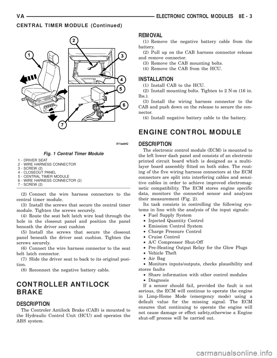
(2) Connect the wire harness connectors to the
central timer module.
(3) Install the screws that secure the central timer
module. Tighten the screws securely.
(4) Route the seat belt latch wire lead through the
hole in the closeout panel and position the panel
beneath the driver seat cushion
(5) Install the screws that secure the closeout
panel beneath the driver seat cushion. Tighten the
screws securely.
(6) Connect the wire harness connector to the seat
belt latch connector.
(7) Slide the driver seat to back to its original posi-
tion.
(8) Reconnect the negative battery cable.
CONTROLLER ANTILOCK
BRAKE
DESCRIPTION
The Controler Antilock Brake (CAB) is mounted to
the Hydraulic Control Unit (HCU) and operates the
ABS system.
REMOVAL
(1) Remove the negative battery cable from the
battery.
(2) Pull up on the CAB harness connector release
and remove connector.
(3) Remove the CAB mounting bolts.
(4) Remove the CAB from the HCU.
INSTALLATION
(1) Install CAB to the HCU.
(2) Install mounting bolts. Tighten to 2 N´m (16 in.
lbs.).
(3) Install the wiring harness connector to the
CAB and push down on the release to secure the con-
nector.
(4) Install negative battery cable to the battery.
ENGINE CONTROL MODULE
DESCRIPTION
The electronic control module (ECM) is mounted to
the left lower dash panel and consists of an electronic
printed circuit board which is designed as a multi-
layer board assembly fitted on both sides. The rout-
ing of the five wiring harness connectors at the ECM
connectors are split into interfering cables and sensi-
tive cables in order to achieve improved electromag-
netic compatibility. The ECM stores engine specific
data, monitors the connected sensor and analyzes
their measurement (Fig. 2).
Its task consists in controlling the following sys-
tems in line with the analysis of the input signals:
²Fuel Supply System
²Injected Quantity Control
²Emission Control System
²Charge Pressure Control
²Cruise Control
²A/C Compressor Shut-Off
²Pre-Heating Output Relay for the Glow Plugs
²Vehicle Theft
²Air Bag
²Monitors inputs/outputs, checks plausibility and
stores faults
²Share information with other control modules
²Diagnosis
If a sensor should fail, provided the fault is not
serious, the ECM will continue to operate the engine
in Limp-Home Mode (emergency mode) using a
default value for the missing signal. The ECM
ensures that continuing to operate the engine will
not cause damage or effect safety,otherwise a Engine
shut-off process will be carried out.Fig. 1 Central Timer Module
1 - DRIVER SEAT
2 - WIRE HARNESS CONNECTOR
3 - SCREW (2)
4 - CLOSEOUT PANEL
5 - CENTRAL TIMER MODULE
6 - WIRE HARNESS CONNECTOR (2)
7 - SCREW (2)
VAELECTRONIC CONTROL MODULES 8E - 3
CENTRAL TIMER MODULE (Continued)
Page 170 of 1232
GLOW PLUG RELAY
DESCRIPTION
The glow plug relay supplies battery voltage to the
glow plug through a timed cycle that is related to
coolant temperature. The glow plug relay is located
under the battery. The purpose of a glow plug system
is to improve combustion for low emissions and to
achieve easy starting at low temperatures.
OPERATION
When the ignition key is turned to the ON position,
the glow plug output stage and pre-glow indicator
lamp are actuated by the ECM. The duration of the
signal depends on the coolant temperature. The glow
plug relay has processing that communicates with the
ECM. If no data exchange occurs at the triggering
stage, the preheating is switched off after 2 seconds.
Start glowing is initiated when the key is in the
start position. The glow plugs (R13±R17) continue to
be supplied with voltage. This makes it possible to
stabilize the cold starting speed. (After glowing is ini-
tiated when the starter reject speed is reached).
After the engine starts, the ECM determines the
afterglow period in line with coolant temperature. If
no signal is received from the coolant temperature
sensor, afterglow is maintained for thirty seconds.
The following aims are reached by the afterglow :²Improvement in warming-up properties
²
Prevention of white exhaust smoke after cold start
²Stabilizing of the cold starting speed
The glow plug output stage constantly signals the
current operating state and faults. The following are
faults detected and transmitted to the ECM :
²Open circuit at one or several glow plugs
²Short circuit in the glow plug circuit
²Relay fault
If the Glow plug relay detects an open circuit at a
glow plug, it is stored and indicated only once the
engine is running by the preglow indicator lamp com-
ing on for about one minute and a fault is stored in
the ECM. If a short circuit, a glow plug output stage
faulty or a temperature related switching off of out-
put stages is detected, the fault is stored and indi-
cated immediately by the preglow indicator lamp
coming on. Once the fault is no longer current, the
indicator is immediately switched off, but the fault is
stored in the ECM. If the fault is constantly current,
the preglow indicator lamp remains on until the igni-
tion is switched off.
DIAGNOSIS AND TESTING - GLOW PLUG
RELAYS
Refer to the appropriate Diesel Powertrain Diagno-
sis Manual for information on diagnosing the glow
plug relays.
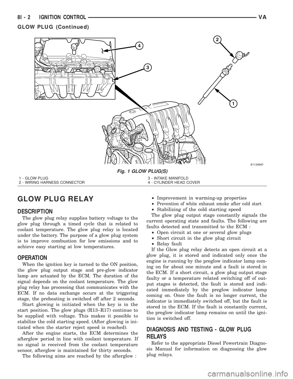
Fig. 1 GLOW PLUG(S)
1 - GLOW PLUG
2 - WIRING HARNESS CONNECTOR3 - INTAKE MANIFOLD
4 - CYLINDER HEAD COVER
8I - 2 IGNITION CONTROLVA
GLOW PLUG (Continued)
Page 196 of 1232
wired input received by the cluster from the turn sig-
nal relay through the turn signal and hazard warn-
ing switch circuitry of the multi-function switch on
the left and right turn signal circuits. Each turn sig-
nal indicator Light Emitting Diode (LED) is com-
pletely controlled by the instrument cluster logic
circuit, and that logic will allow this indicator to
operate whenever the instrument cluster receives a
battery current input on the fused B(+) circuit.
Therefore, each LED can be illuminated regardless of
the ignition switch position. The LED only illumi-
nates when it is provided a path to ground by the
instrument cluster transistor. The instrument cluster
will turn on the turn signal indicators for the follow-
ing reasons:
²Turn Signal Input- Each time the cluster
detects a turn signal input from the turn signal relay
through the closed turn signal switch circuitry of the
multi-function switch on the hard wired left or right
turn signal circuit, the requested turn signal lamps
and turn signal indicator will be flashed on and off,
and a contactless relay soldered onto the cluster elec-
tronic circuit board will produce a clicking sound to
emulate a conventional turn signal flasher. The turn
signals and the turn signal indicators continue to
flash on and off until the turn signal switch circuitry
of the multi-function switch is opened, or until the
ignition switch is turned to the Off position, which-
ever occurs first.
²Hazard Warning Input- Each time the cluster
detects a hazard warning input from the turn signal
relay through the closed hazard warning switch cir-
cuitry of the multi-function switch on the hard wired
left and right turn signal circuits, all of the turn sig-
nal lamps and both turn signal indicators will be
flashed on and off, and a contactless relay soldered
onto the cluster electronic circuit board will produce
a clicking sound to emulate a conventional hazard
warning flasher. The turn signals and the turn signal
indicators continue to flash on and off until the haz-
ard warning switch circuitry of the multi-function
switch is opened.
An electronic wipers, turn signals and engine start
control module located within the fuse block beneath
the steering column monitors the turn signal circuits
and controls the flash rate of the turn signal relay.
The instrument cluster continually monitors the
right and left turn signal circuits to determine the
proper turn signal and hazard warning indicator
operation, then flashes the proper turn signal indica-
tors and the contactless relay on and off accordingly.
The multi-function switch, the turn signal relay and
the left and right turn signal circuits to the instru-
ment cluster can be diagnosed using conventional
diagnostic tools and methods. For proper diagnosis of
the wipers, turn signals and engine start controlmodule within the fuse block or the instrument clus-
ter circuitry that controls the turn signal indicators
and the contactless relay, a DRBIIItscan tool is
required. Refer to the appropriate diagnostic infor-
mation.
WAIT-TO-START INDICATOR
DESCRIPTION
A wait-to-start indicator is standard equipment in
all instrument clusters. The wait-to-start indicator is
located near the lower edge of the instrument cluster,
to the right of the multi-function indicator display.
The wait-to-start indicator consists of the Interna-
tional Control and Display Symbol icon for ªDiesel
Preheatº imprinted within a rectangular cutout in
the opaque layer of the instrument cluster overlay.
The dark outer layer of the overlay prevents the indi-
cator from being clearly visible when it is not illumi-
nated. An amber Light Emitting Diode (LED) behind
the cutout in the opaque layer of the overlay causes
the icon to appear silhouetted against an amber field
through the translucent outer layer of the overlay
when the indicator is illuminated from behind by the
LED, which is soldered onto the instrument cluster
electronic circuit board. The wait-to-start indicator is
serviced as a unit with the instrument cluster.
OPERATION
The wait-to-start indicator gives an indication to
the vehicle operator when the diesel engine glow
plugs are energized in their pre-heat operating mode.
This indicator is controlled by a transistor on the
instrument cluster circuit board based upon cluster
programming and electronic messages received by
the cluster from the Engine Control Module (ECM)
over the Controller Area Network (CAN) data bus.
The wait-to-start indicator Light Emitting Diode
(LED) is completely controlled by the instrument
cluster logic circuit, and that logic will only allow
this indicator to operate when the instrument cluster
detects that the ignition switch is in the On position.
Therefore, the LED will always be off when the igni-
tion switch is in any position except On. The LED
only illuminates when it is provided a path to ground
by the instrument cluster transistor. The instrument
cluster will turn on the wait-to-start indicator for the
following reasons:
²Bulb Test- Each time the ignition switch is
turned to the On position the wait-to-start indicator
is illuminated for about two seconds as a bulb test.
²Wait-To-Start Lamp-On Message- Each time
the cluster receives a wait-to-start lamp-on message
from the ECM indicating that the diesel engine glow
plugs are energized in their pre-heat operating mode,
8J - 26 INSTRUMENT CLUSTERVA
TURN SIGNAL INDICATOR (Continued)
Page 197 of 1232
the wait-to-start indicator will be illuminated. The
indicator remains illuminated until the cluster
receives a wait-to-start lamp-off message indicating
that the pre-heat mode of the glow plugs has been
completed, until the ECM detects that the engine is
running, or until the ignition switch is turned to the
Off position, whichever occurs first.
The ECM continually monitors the engine coolant
temperature sensor to determine when the glow
plugs need to be energized in their pre-heat operat-
ing mode. The ECM then sends the proper wait-to-
start lamp-on and lamp-off messages to the
instrument cluster. If the instrument cluster turns on
the indicator after the engine is started, it may indi-
cate that a malfunction has occurred and that the
engine glow control system requires service. The
ECM will store a Diagnostic Trouble Code (DTC) for
any malfunction it detects. For proper diagnosis of
the engine coolant temperature sensor, the engine
glow control system and circuits, the ECM, the CAN
data bus, or the electronic message inputs to the
instrument cluster that control the wait-to-start indi-
cator, a DRBIIItscan tool is required. Refer to the
appropriate diagnostic information.
WASHER FLUID INDICATOR
DESCRIPTION
A washer fluid indicator is standard equipment on
all instrument clusters. However, this indicator is
only functional on vehicles equipped with an optional
washer fluid level switch integral to the washer
pump/motor unit on the washer reservoir. The
washer fluid indicator is located near the lower edge
of the instrument cluster, to the right of the multi-
function indicator display. The washer fluid indicator
consists of the International Control and Display
Symbol icon for ªWindshield Washer Fluidº imprinted
within a rectangular cutout in the opaque layer of
the instrument cluster overlay. The dark outer layer
of the overlay prevents the indicator from being
clearly visible when it is not illuminated. An amber
Light Emitting Diode (LED) behind the cutout in the
opaque layer of the overlay causes the icon to appear
silhouetted against an amber field through the trans-
lucent outer layer of the overlay when the indicator
is illuminated from behind by the LED, which is sol-
dered onto the instrument cluster electronic circuit
board. The washer fluid indicator is serviced as a
unit with the instrument cluster.
OPERATION
The washer fluid indicator gives an indication to
the vehicle operator that the fluid level in the washer
reservoir is low. This indicator is controlled by theinstrument cluster circuit board based upon cluster
programming and a hard wired input from the
optional washer fluid level switch that is integral to
the washer pump/motor unit. The washer fluid indi-
cator is completely controlled by the instrument clus-
ter logic circuit, and that logic will only allow this
indicator to operate when the instrument cluster
detects that the ignition switch is in the On position.
Therefore, the indicator will always be off when the
ignition switch is in any position except On. The indi-
cator only illuminates when it is switched to ground
by the instrument cluster circuitry. The instrument
cluster will turn on the washer fluid indicator for the
following reasons:
²Bulb Test- Each time the ignition switch is
turned to the On position the brake wear indicator is
illuminated by the instrument cluster for about two
seconds as a bulb test.
²Washer Fluid Level Switch Input- Each time
the cluster detects ground on the washer fluid switch
sense circuit (washer fluid level switch closed =
washer fluid level low) while the ignition switch is in
the On position, the washer fluid indicator is illumi-
nated. The indicator remains illuminated until the
washer fluid level switch input to the cluster is an
open circuit (washer fluid level switch open = washer
fluid level acceptable), or until the ignition switch is
turned to the Off position, whichever occurs first.
The instrument cluster continually monitors the
washer fluid level switch to determine the level of
the washer fluid. The instrument cluster logic applies
a delay strategy to this input to reduce the negative
effect that fluid sloshing within the reservoir can
have on reliable indicator operation. The washer
fluid level switch and circuit can be diagnosed using
conventional diagnostic tools and methods. For
proper diagnosis of the instrument cluster circuitry
that controls the washer fluid indicator, a DRBIIIt
scan tool is required. Refer to the appropriate diag-
nostic information.
WATER-IN-FUEL INDICATOR
DESCRIPTION
A water-in-fuel indicator is standard equipment in
all instrument clusters. The water-in-fuel indicator is
located near the lower edge of the instrument cluster,
to the left of the multi-function indicator display. The
water-in-fuel indicator consists of the International
Control and Display Symbol icon for ªWater In Fuelº
imprinted within a rectangular cutout in the opaque
layer of the instrument cluster overlay. The dark
outer layer of the overlay prevents the indicator from
being clearly visible when it is not illuminated. An
amber Light Emitting Diode (LED) behind the cutout
VAINSTRUMENT CLUSTER 8J - 27
WAIT-TO-START INDICATOR (Continued)
Page 317 of 1232
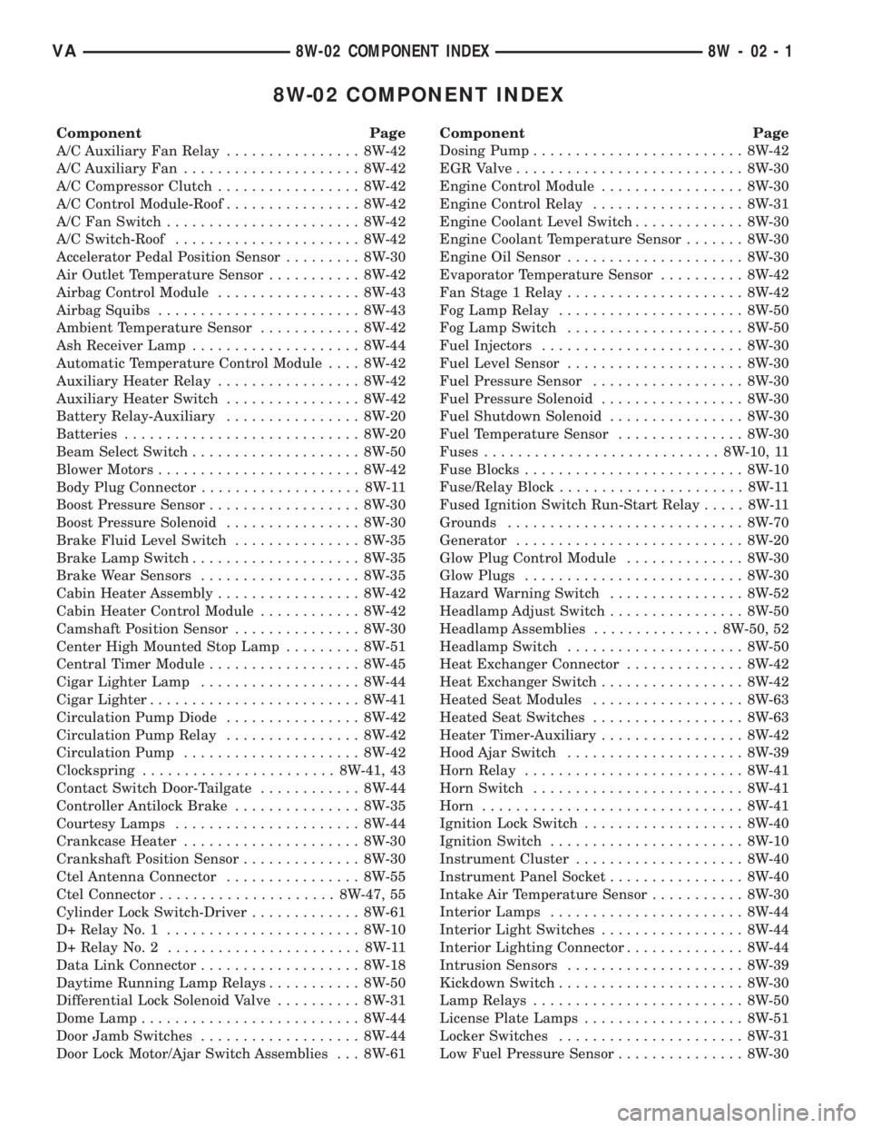
8W-02 COMPONENT INDEX
Component Page
A/C Auxiliary Fan Relay................ 8W-42
A/C Auxiliary Fan..................... 8W-42
A/C Compressor Clutch................. 8W-42
A/C Control Module-Roof................ 8W-42
A/C Fan Switch....................... 8W-42
A/C Switch-Roof...................... 8W-42
Accelerator Pedal Position Sensor......... 8W-30
Air Outlet Temperature Sensor........... 8W-42
Airbag Control Module................. 8W-43
Airbag Squibs........................ 8W-43
Ambient Temperature Sensor............ 8W-42
Ash Receiver Lamp.................... 8W-44
Automatic Temperature Control Module.... 8W-42
Auxiliary Heater Relay................. 8W-42
Auxiliary Heater Switch................ 8W-42
Battery Relay-Auxiliary................ 8W-20
Batteries............................ 8W-20
Beam Select Switch.................... 8W-50
Blower Motors........................ 8W-42
Body Plug Connector................... 8W-11
Boost Pressure Sensor.................. 8W-30
Boost Pressure Solenoid................ 8W-30
Brake Fluid Level Switch............... 8W-35
Brake Lamp Switch.................... 8W-35
Brake Wear Sensors................... 8W-35
Cabin Heater Assembly................. 8W-42
Cabin Heater Control Module............ 8W-42
Camshaft Position Sensor............... 8W-30
Center High Mounted Stop Lamp......... 8W-51
Central Timer Module.................. 8W-45
Cigar Lighter Lamp................... 8W-44
Cigar Lighter......................... 8W-41
Circulation Pump Diode................ 8W-42
Circulation Pump Relay................ 8W-42
Circulation Pump..................... 8W-42
Clockspring....................... 8W-41, 43
Contact Switch Door-Tailgate............ 8W-44
Controller Antilock Brake............... 8W-35
Courtesy Lamps...................... 8W-44
Crankcase Heater..................... 8W-30
Crankshaft Position Sensor.............. 8W-30
Ctel Antenna Connector................ 8W-55
Ctel Connector..................... 8W-47, 55
Cylinder Lock Switch-Driver............. 8W-61
D+ Relay No. 1....................... 8W-10
D+ Relay No. 2....................... 8W-11
Data Link Connector................... 8W-18
Daytime Running Lamp Relays........... 8W-50
Differential Lock Solenoid Valve.......... 8W-31
Dome Lamp.......................... 8W-44
Door Jamb Switches................... 8W-44
Door Lock Motor/Ajar Switch Assemblies . . . 8W-61Component Page
Dosing Pump......................... 8W-42
EGR Valve........................... 8W-30
Engine Control Module................. 8W-30
Engine Control Relay.................. 8W-31
Engine Coolant Level Switch............. 8W-30
Engine Coolant Temperature Sensor....... 8W-30
Engine Oil Sensor..................... 8W-30
Evaporator Temperature Sensor.......... 8W-42
Fan Stage 1 Relay..................... 8W-42
Fog Lamp Relay...................... 8W-50
Fog Lamp Switch..................... 8W-50
Fuel Injectors........................ 8W-30
Fuel Level Sensor..................... 8W-30
Fuel Pressure Sensor.................. 8W-30
Fuel Pressure Solenoid................. 8W-30
Fuel Shutdown Solenoid................ 8W-30
Fuel Temperature Sensor............... 8W-30
Fuses............................ 8W-10, 11
Fuse Blocks.......................... 8W-10
Fuse/Relay Block...................... 8W-11
Fused Ignition Switch Run-Start Relay..... 8W-11
Grounds............................ 8W-70
Generator........................... 8W-20
Glow Plug Control Module.............. 8W-30
Glow Plugs.......................... 8W-30
Hazard Warning Switch................ 8W-52
Headlamp Adjust Switch................ 8W-50
Headlamp Assemblies............... 8W-50, 52
Headlamp Switch..................... 8W-50
Heat Exchanger Connector.............. 8W-42
Heat Exchanger Switch................. 8W-42
Heated Seat Modules.................. 8W-63
Heated Seat Switches.................. 8W-63
Heater Timer-Auxiliary................. 8W-42
Hood Ajar Switch..................... 8W-39
Horn Relay.......................... 8W-41
Horn Switch......................... 8W-41
Horn............................... 8W-41
Ignition Lock Switch................... 8W-40
Ignition Switch....................... 8W-10
Instrument Cluster.................... 8W-40
Instrument Panel Socket................ 8W-40
Intake Air Temperature Sensor........... 8W-30
Interior Lamps....................... 8W-44
Interior Light Switches................. 8W-44
Interior Lighting Connector.............. 8W-44
Intrusion Sensors..................... 8W-39
Kickdown Switch...................... 8W-30
Lamp Relays......................... 8W-50
License Plate Lamps................... 8W-51
Locker Switches...................... 8W-31
Low Fuel Pressure Sensor............... 8W-30
VA8W-02 COMPONENT INDEX 8W - 02 - 1
Page 739 of 1232
ENGINE
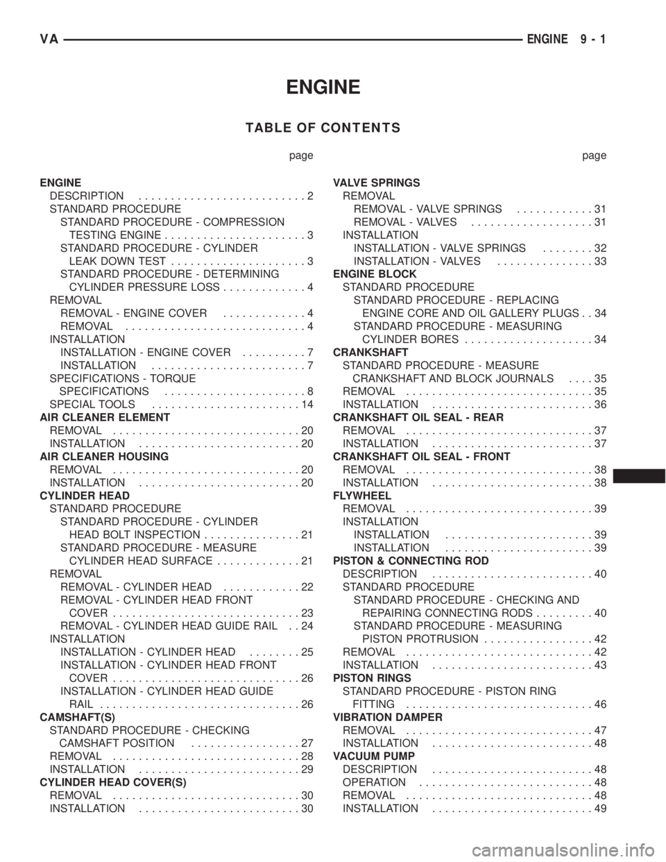
TABLE OF CONTENTS
page page
ENGINE
DESCRIPTION..........................2
STANDARD PROCEDURE
STANDARD PROCEDURE - COMPRESSION
TESTING ENGINE......................3
STANDARD PROCEDURE - CYLINDER
LEAK DOWN TEST.....................3
STANDARD PROCEDURE - DETERMINING
CYLINDER PRESSURE LOSS.............4
REMOVAL
REMOVAL - ENGINE COVER.............4
REMOVAL............................4
INSTALLATION
INSTALLATION - ENGINE COVER..........7
INSTALLATION........................7
SPECIFICATIONS - TORQUE
SPECIFICATIONS......................8
SPECIAL TOOLS.......................14
AIR CLEANER ELEMENT
REMOVAL.............................20
INSTALLATION.........................20
AIR CLEANER HOUSING
REMOVAL.............................20
INSTALLATION.........................20
CYLINDER HEAD
STANDARD PROCEDURE
STANDARD PROCEDURE - CYLINDER
HEAD BOLT INSPECTION...............21
STANDARD PROCEDURE - MEASURE
CYLINDER HEAD SURFACE.............21
REMOVAL
REMOVAL - CYLINDER HEAD............22
REMOVAL - CYLINDER HEAD FRONT
COVER.............................23
REMOVAL - CYLINDER HEAD GUIDE RAIL . . 24
INSTALLATION
INSTALLATION - CYLINDER HEAD........25
INSTALLATION - CYLINDER HEAD FRONT
COVER.............................26
INSTALLATION - CYLINDER HEAD GUIDE
RAIL...............................26
CAMSHAFT(S)
STANDARD PROCEDURE - CHECKING
CAMSHAFT POSITION.................27
REMOVAL.............................28
INSTALLATION.........................29
CYLINDER HEAD COVER(S)
REMOVAL.............................30
INSTALLATION.........................30VALVE SPRINGS
REMOVAL
REMOVAL - VALVE SPRINGS............31
REMOVAL - VALVES...................31
INSTALLATION
INSTALLATION - VALVE SPRINGS........32
INSTALLATION - VALVES...............33
ENGINE BLOCK
STANDARD PROCEDURE
STANDARD PROCEDURE - REPLACING
ENGINE CORE AND OIL GALLERY PLUGS . . 34
STANDARD PROCEDURE - MEASURING
CYLINDER BORES....................34
CRANKSHAFT
STANDARD PROCEDURE - MEASURE
CRANKSHAFT AND BLOCK JOURNALS....35
REMOVAL.............................35
INSTALLATION.........................36
CRANKSHAFT OIL SEAL - REAR
REMOVAL.............................37
INSTALLATION.........................37
CRANKSHAFT OIL SEAL - FRONT
REMOVAL.............................38
INSTALLATION.........................38
FLYWHEEL
REMOVAL.............................39
INSTALLATION
INSTALLATION.......................39
INSTALLATION.......................39
PISTON & CONNECTING ROD
DESCRIPTION.........................40
STANDARD PROCEDURE
STANDARD PROCEDURE - CHECKING AND
REPAIRING CONNECTING RODS.........40
STANDARD PROCEDURE - MEASURING
PISTON PROTRUSION.................42
REMOVAL.............................42
INSTALLATION.........................43
PISTON RINGS
STANDARD PROCEDURE - PISTON RING
FITTING.............................46
VIBRATION DAMPER
REMOVAL.............................47
INSTALLATION.........................48
VACUUM PUMP
DESCRIPTION.........................48
OPERATION...........................48
REMOVAL.............................48
INSTALLATION.........................49
VAENGINE 9 - 1
Page 741 of 1232
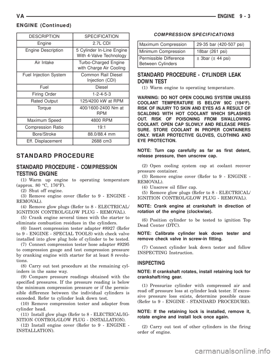
DESCRIPTION SPECIFICATION
Engine 2.7L CDI
Engine Description 5 Cylinder In-Line Engine
With 4-Valve Technology
Air Intake Turbo-Charged Engine
with Charge Air Cooling
Fuel Injection System Common Rail Diesel
Injection (CDI)
Fuel Diesel
Firing Order 1-2-4-5-3
Rated Output 125/4200 kW at RPM
Torque 400/1600-2400 Nm at
RPM
Maximum Speed 4800 RPM
Compression Ratio 19:1
Bore/Stroke 88.0/88.4 mm
Eff. Displacement 2688 cm3
STANDARD PROCEDURE
STANDARD PROCEDURE - COMPRESSION
TESTING ENGINE
(1) Warm up engine to operating temperature
(approx. 80 ÉC, 176ÉF).
(2) Shut off engine.
(3) Remove engine cover (Refer to 9 - ENGINE -
REMOVAL).
(4) Remove glow plugs (Refer to 8 - ELECTRICAL/
IGNITION CONTROL/GLOW PLUG - REMOVAL).
(5) Crank engine several times with the starter to
eliminate combustion residues in the cylinders.
(6) Insert compression tester adapter #8927 (Refer
to 9 - ENGINE - SPECIAL TOOLS) with check valve
installed into glow plug hole of cylinder to be tested.
(7) Connect compression tester hose adapter #9295
to compression gauge and test compression pressure
by cranking engine with starter for at least 8 revolu-
tions.
(8) Carry out test procedure at the remaining cyl-
inders in the same way.
(9) Compare pressure readings obtained with the
specified pressures. If the pressure reading is below
the minimum compression pressure or if the permis-
sible difference between the individual cylinders is
exceeded. Refer to cylinder leak down test.
(10) Remove compression tester and adapter from
cylinder head.
(11)
Install glow plugs (Refer to 8 - ELECTRICAL/IG-
NITION CONTROL/GLOW PLUG - INSTALLATION).
(12) Install engine cover (Refer to 9 - ENGINE -
INSTALLATION).
COMPRESSION SPECIFICATIONS
Maximum Compression 29-35 bar (420-507 psi)
Minimum Compression 18bar (261 psi)
Permissible Difference
Between Cylinders 3bar ( 44 psi)
STANDARD PROCEDURE - CYLINDER LEAK
DOWN TEST
(1) Warm engine to operating temperature.
WARNING: DO NOT OPEN COOLING SYSTEM UNLESS
COOLANT TEMPERATURE IS BELOW 90C (194ÉF).
RISK OF INJURY TO SKIN AND EYES AS A RESULT OF
SCALDING WITH HOT COOLANT WHICH SPLASHES
OUT. RISK OF POISONING FROM SWALLOWING
COOLANT. OPEN CAP SLOWLY AND RELEASE PRES-
SURE. STORE COOLANT IN PROPER CONTAINERS
ONLY. WEAR PROTECTIVE GLOVES, CLOTHING AND
EYE PROTECTION.
NOTE: Turn cap carefully as far as first detent,
release pressure, then unscrew cap.
(2) Open cooling system cap at coolant recover
pressure container.
(3) Remove engine cover (Refer to 9 - ENGINE -
REMOVAL).
(4) Unscrew oil filler cap.
(5) Remove glow plugs (Refer to 8 - ELECTRICAL/
IGNITION CONTROL/GLOW PLUG - REMOVAL).
NOTE: Crank engine at crankshaft in direction of
rotation of the engine (clockwise).
(6) Position cylinder to be tested to ignition Top
Dead Center (DTC).
NOTE: Calibrate cylinder leak down tester and
remove check valve in screw-in fitting.
(7) Connect cylinder leak down tester and follow
INSPECTING Instruction.
INSPECTING
NOTE: If crankshaft rotates, install retaining lock for
crankshaft/ring gear.
(1) Pressurize cylinder with compressed air and
read off pressure loss at cylinder leak tester. If exces-
sive pressure loss exists, determine possible cause
(Refer to 9 - ENGINE - STANDARD PROCEDURE).
NOTE: If the retaining lock is installed, remove it,
rotate engine and install lock once again.
(2) Carry out test of other cylinders in the firing
order of engine.
VAENGINE 9 - 3
ENGINE (Continued)
Page 742 of 1232
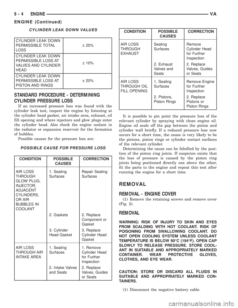
CYLINDER LEAK DOWN VALUES
CYLINDER LEAK DOWN
PERMISSIBLE TOTAL
LOSS 25%
CYLINDER LEAK DOWN
PERMISSIBLE LOSS AT
VALVES AND CYLINDER
HEAD 10%
CYLINDER LEAK DOWN
PERMISSIBLE LOSS AT
PISTON AND RINGS 20%
STANDARD PROCEDURE - DETERMINING
CYLINDER PRESSURE LOSS
If an increased pressure loss was found with the
cylinder leak test, inspect the engine by listening at
the cylinder head gasket, air intake area, exhaust, oil
fill opening and where injectors and glow plugs enter
the cylinder head. Also check the engine coolant in
the radiator or expansion reservoir for the formation
of bubbles.
Possible causes for the pressure loss are:
POSSIBLE CAUSE FOR PRESSURE LOSS
CONDITION POSSIBLE
CAUSESCORRECTION
AIR LOSS
THROUGH
GLOW PLUG,
INJECTOR,
ADJACENT
CYLINDERS,
OR AIR
BUBBLES IN
COOLANT1. Sealing
SurfacesRepair Sealing
Surfaces
2. Gaskets 2. Replace
Component or
Gasket
3. Cylinder
Head Gasket3. Replace
Cylinder Head
Gasket
AIR LOSS
THROUGH AIR
INTAKE AREA1. Sealing
Surfaces1. Remove
Cylinder Head
for Further
Inspection
2. Intake Valves
and Seats2. Replace
Valves, Guides
or Seats
CONDITION POSSIBLE
CAUSESCORRECTION
AIR LOSS
THROUGH
EXHAUSTSealing
SurfacesRemove
Cylinder Head
for Further
Inspection
2. Exhaust
Valves and
Seats2. Replace
Valves, Guides
or Seats
AIR LOSS
THROUGH OIL
FILL OPENING1. Sealing
SurfacesRemove Engine
for Further
Inspection
2. Pistons,
Piston Rings2. Replace
Pistons or
Piston Rings
It is possible to pin point the pressure loss of the
relevant cylinder by spraying with clean engine oil.
Engine oil seals off the gap between the piston and
cylinder wall briefly. If a reduced pressure loss now
occurs for a short time, the cause is very likely to be
the pistons, piston rings or cylinder contact surfaces
of the relevant cylinder.
Determining the cause can be falsified by the posi-
tion of the piston ring joints. If suspicion exists that
the loss of pressure is caused by the piston ring
joints being positioned directly one above the other,
fit the parts to the engine and repeat this test after
running the engine for a short time.
REMOVAL
REMOVAL - ENGINE COVER
(1) Remove the retaining screws and remove cover
(Fig. 2).
REMOVAL
WARNING: RISK OF INJURY TO SKIN AND EYES
FROM SCALDING WITH HOT COOLANT. RISK OF
POISONING FROM SWALLOWING COOLANT. DO
NOT OPEN COOLING SYSTEM UNLESS COOLANT
TEMPERATURE IS BELOW 90ÉC (194ÉF). OPEN CAP
SLOWLY TO RELEASE PRESSURE. STORE COOL-
ANT IN SUITABLE AND APPROPRIATELY MARKED
CONTAINER. WEAR PROTECTIVE GLOVES,
CLOTHES, AND EYE WEAR.
CAUTION: STORE OR DISCARD ALL FLUIDS IN
SUITABLE AND APPROPRIATELY MARKED CON-
TAINERS.
(1) Disconnect the negative battery cable.
9 - 4 ENGINEVA
ENGINE (Continued)