2005 MERCEDES-BENZ SPRINTER oil change
[x] Cancel search: oil changePage 798 of 1232
(6) Remove the oil filter to allow the oil to flow off
into the oil pan.
(7) Remove the radiator assembly (Refer to 7 -
COOLING/ENGINE/RADIATOR - REMOVAL).
(8) Remove engine cover (Refer to 9 - ENGINE -
REMOVAL).
(9) Remove front cover at cylinder head (Refer to 9
- ENGINE/CYLINDER HEAD - REMOVAL).
(10) Remove accessory drive belt.
(11) Remove the high pressure fuel pump (Refer to
14 - FUEL SYSTEM/FUEL DELIVERY/FUEL PUMP
- REMOVAL).
(12) Remove water pump (Refer to 7 - COOLING/
ENGINE/WATER PUMP - REMOVAL).
(13) Remove accessory drive belt pulley and vibra-
tion damper (Refer to 9 - ENGINE/ENGINE BLOCK/
VIBRATION DAMPER - REMOVAL).
(14) Remove the power steering pump.
NOTE: NO NOT open the air conditioning system.
(15) Unplug AC compressor electrical connector
and unbolt AC compressor. Relocate in lower engine
compartmentwith outopening the system.
(16) Remove the generator with wiring attached
and relocate somewhere in the engine compartment.
(17) Install engine support fixture.
(18) Remove the oil pan.
(19) Detach the coolant hose to oil-water heat
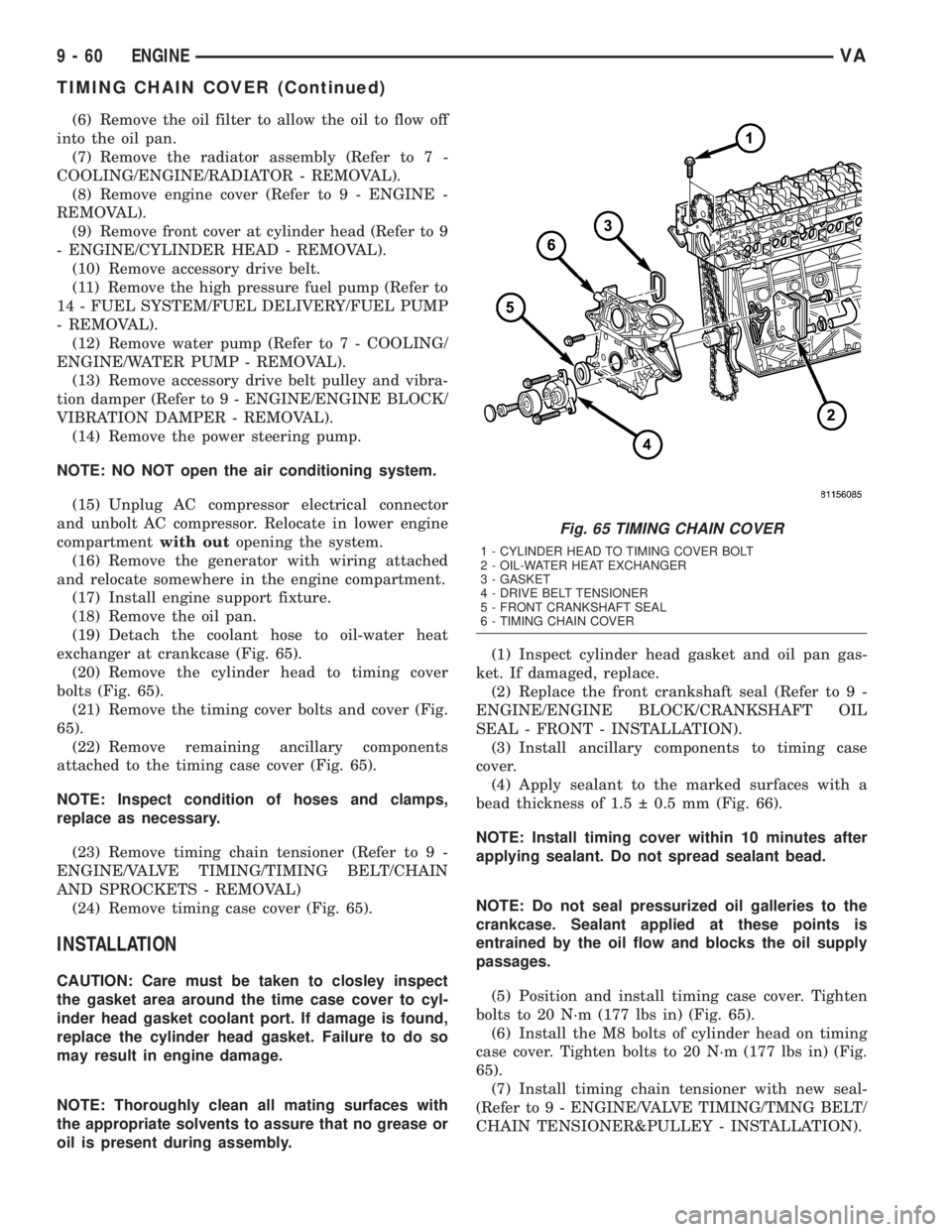
exchanger at crankcase (Fig. 65).
(20) Remove the cylinder head to timing cover
bolts (Fig. 65).
(21) Remove the timing cover bolts and cover (Fig.
65).
(22) Remove remaining ancillary components
attached to the timing case cover (Fig. 65).
NOTE: Inspect condition of hoses and clamps,
replace as necessary.
(23) Remove timing chain tensioner (Refer to 9 -
ENGINE/VALVE TIMING/TIMING BELT/CHAIN
AND SPROCKETS - REMOVAL)
(24) Remove timing case cover (Fig. 65).
INSTALLATION
CAUTION: Care must be taken to closley inspect
the gasket area around the time case cover to cyl-
inder head gasket coolant port. If damage is found,
replace the cylinder head gasket. Failure to do so
may result in engine damage.
NOTE: Thoroughly clean all mating surfaces with
the appropriate solvents to assure that no grease or
oil is present during assembly.(1) Inspect cylinder head gasket and oil pan gas-
ket. If damaged, replace.
(2) Replace the front crankshaft seal (Refer to 9 -
ENGINE/ENGINE BLOCK/CRANKSHAFT OIL
SEAL - FRONT - INSTALLATION).
(3) Install ancillary components to timing case
cover.
(4) Apply sealant to the marked surfaces with a
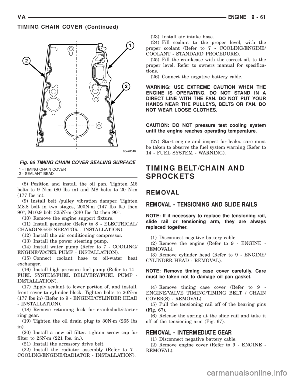
bead thickness of 1.5 0.5 mm (Fig. 66).
NOTE: Install timing cover within 10 minutes after
applying sealant. Do not spread sealant bead.
NOTE: Do not seal pressurized oil galleries to the
crankcase. Sealant applied at these points is
entrained by the oil flow and blocks the oil supply
passages.
(5) Position and install timing case cover. Tighten
bolts to 20 N´m (177 lbs in) (Fig. 65).
(6) Install the M8 bolts of cylinder head on timing
case cover. Tighten bolts to 20 N´m (177 lbs in) (Fig.
65).
(7) Install timing chain tensioner with new seal-
(Refer to 9 - ENGINE/VALVE TIMING/TMNG BELT/
CHAIN TENSIONER&PULLEY - INSTALLATION).
Fig. 65 TIMING CHAIN COVER
1 - CYLINDER HEAD TO TIMING COVER BOLT
2 - OIL-WATER HEAT EXCHANGER
3 - GASKET
4 - DRIVE BELT TENSIONER
5 - FRONT CRANKSHAFT SEAL
6 - TIMING CHAIN COVER
9 - 60 ENGINEVA
TIMING CHAIN COVER (Continued)
Page 799 of 1232
(8) Position and install the oil pan. Tighten M6
bolts to 9 N´m (80 lbs in) and M8 bolts to 20 N´m
(177 lbs in).
(9) Install belt /pulley vibration damper. Tighten
M8.8 bolt in two stages, 200N´m (147 lbs ft.) then
90É, M10.9 bolt 325N´m (240 lbs ft) then 90É.
(10) Remove the engine support fixture.
(11) Install generator (Refer to 8 - ELECTRICAL/
CHARGING/GENERATOR - INSTALLATION).
(12) Install the air conditioning compressor.
(13) Install the power steering pump.
(14) Install water pump (Refer to 7 - COOLING/
ENGINE/WATER PUMP - INSTALLATION).
(15) Connect coolant hose to oil-water heat
exchanger.
(16) Install high pressure fuel pump (Refer to 14 -
FUEL SYSTEM/FUEL DELIVERY/FUEL PUMP -
INSTALLATION).
(17) Apply sealant to lower portion of, and install,
front cover to cylinder block. Tighten bolts to 20N´m
(177 lbs in) (Refer to 9 - ENGINE/CYLINDER HEAD
- INSTALLATION).
(18) Remove retaining lock for crankshaft/starter
ring gear.
(19) Tighten the oil drain plug to 30N´m (265 lbs
in).
(20) Install a new oil filter. tighten screw cap for
filter to 25N´m (221 lbs. in.).
(21) Install the accessory drive belt.
(22) Install the radiator assembly (Refer to 7 -
COOLING/ENGINE/RADIATOR - INSTALLATION).(23) Install air intake hose.
(24) Fill coolant to the proper level, with the
proper coolant (Refer to 7 - COOLING/ENGINE/
COOLANT - STANDARD PROCEDURE).
(25) Fill the crankcase with the correct oil, to the
proper level. Refer to owners manual for specifica-
tions.
(26) Connect the negative battery cable.
WARNING: USE EXTREME CAUTION WHEN THE
ENGINE IS OPERATING. DO NOT STAND IN A
DIRECT LINE WITH THE FAN. DO NOT PUT YOUR
HANDS NEAR THE PULLEYS, BELTS OR FAN. DO
NOT WEAR LOOSE CLOTHES.
CAUTION: DO NOT pressure test cooling system
until the engine reaches operating temperature.
(27) Start engine and inspect for leaks. care must
be taken to observe the fuel system warning (Refer to
14 - FUEL SYSTEM - WARNING).
TIMING BELT/CHAIN AND
SPROCKETS
REMOVAL
REMOVAL - TENSIONING AND SLIDE RAILS
NOTE: If it necessary to replace the tensioning rail,
slide rail or tensioning arm, they are always
replaced together.
(1) Disconnect negative battery cable.
(2) Remove the engine (Refer to 9 - ENGINE -
REMOVAL).
(3) Remove cylinder head (Refer to 9 - ENGINE/
CYLINDER HEAD - REMOVAL).
NOTE: Remove timing case cover carefully. Care
must be taken not to damage oil pan gasket.
(4) Remove timing case cover (Refer to 9 -
ENGINE/VALVE TIMING/TIMING BELT / CHAIN
COVER(S) - REMOVAL).
(5) Pull the tensioning rail off of the bearing pins
(Fig. 67).
(6) Release the spring at the slide rail and take it
off of the tensioning arm (Fig. 67).
REMOVAL - INTERMEDIATE GEAR
(1) Disconnect negative battery cable.
(2) Remove engine cover (Refer to 9 - ENGINE -
REMOVAL).
Fig. 66 TIMING CHAIN COVER SEALING SURFACE
1 - TIMING CHAIN COVER
2 - SEALANT BEAD
VAENGINE 9 - 61
TIMING CHAIN COVER (Continued)
Page 814 of 1232
²Higher torque as a result of improved cylinder
charge.
²Reduction in exhaust emissions as a result of an
improvement in the air supply of the engine.
²Increased power output as a result of the higher
charge pressure combined with a reduced exhaust
backpressure and thus improved charge cycle.
OPERATION
The exhaust gases of the engine are directed
through the exhaust manifold into the turbine hous-
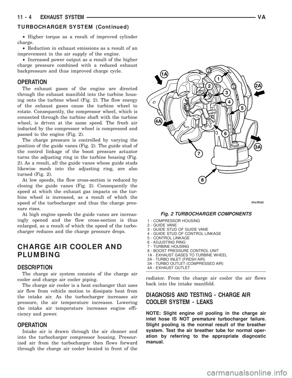
ing onto the turbine wheel (Fig. 2). The flow energy
of the exhaust gases cause the turbine wheel to
rotate. Consequently, the compressor wheel, which is
connected through the turbine shaft with the turbine
wheel, is driven at the same speed. The fresh air
inducted by the compressor wheel is compressed and
passed to the engine (Fig. 2).
The charge pressure is controlled by varying the
position of the guide vanes (Fig. 2). The guide stud of
the control linkage of the boost pressure actuator
turns the adjusting ring in the turbine housing (Fig.
2). As a result, all the guide vanes whose guide studs
likewise mesh into the adjusting ring, are also
turned (Fig. 2).
At low speeds, the flow cross-section is reduced by
closing the guide vanes (Fig. 2). Consequently the
speed at which the exhaust gas impacts on the tur-
bine wheel is increased, as a result of which the
speed of the turbocharger and thus the charge pres-
sure rises.
At high engine speeds the guide vanes are increas-
ingly opened and the flow cross-section is thus
enlarged, as a result of which the speed of the turbo-
charger reduces and the charge pressure drops.
CHARGE AIR COOLER AND
PLUMBING
DESCRIPTION
The charge air system consists of the charge air
cooler and charge air cooler piping.
The charge air cooler is a heat exchanger that uses
air flow from vehicle motion to dissipate heat from
the intake air. As the turbocharger increases air
pressure, the air temperature increases. Lowering
the intake air temperature increases engine effi-
ciency and power.
OPERATION
Intake air is drawn through the air cleaner and
into the turbocharger compressor housing. Pressur-
ized air from the turbocharger then flows forward
through the charge air cooler located in front of theradiator. From the charge air cooler the air flows
back into the intake manifold.
DIAGNOSIS AND TESTING - CHARGE AIR
COOLER SYSTEM - LEAKS
NOTE: Slight engine oil pooling in the charge air
inlet hose IS NOT premature turbocharger failure.
Slight pooling is the normal result of the breather
system. Test the air breather tube for normal oper-
ation by referring to the appropriate diagnostic
manual.
Fig. 2 TURBOCHARGER COMPONENTS
1 - COMPRESSOR HOUSING
2 - GUIDE VANE
3 - GUIDE STUD OF GUIDE VANE
4 - GUIDE STUD OF CONTROL LINKAGE
5 - CONTROL LINKAGE
6 - ADJUSTING RING
7 - TURBINE HOUSING
8 - BOOST PRESSURE CONTROL UNIT
1A - EXHAUST GASES TO TURBINE WHEEL
2A - TURBO INLET (FRESH AIR)
3A - TURBO OUTLET (COMPRESSED AIR)
4A - EXHAUST OUTLET
11 - 4 EXHAUST SYSTEMVA
TURBOCHARGER SYSTEM (Continued)
Page 861 of 1232
STEERING
TABLE OF CONTENTS
page page
STEERING
DESCRIPTION..........................1
OPERATION............................1
DIAGNOSIS AND TESTING - POWER
STEERING SYSTEM....................2COLUMN...............................5
GEAR..................................8
LINKAGE..............................10
PUMP.................................12
STEERING
DESCRIPTION
CAUTION: Mopar ATF+4 Automatic Transmission
fluid or equivalent is to be used in the power steer-
ing system. No other power steering or automatic
transmission fluid is to be used in the system.
Damage may result to the power steering pump and
system if any other fluid is used, and do not over-
fill.
Power steering systems consist of:
²Steering column
²Rack and pinion steering gear
²Belt driven hydraulic steering pump
²Pump pressure and return hoses
²Oil Cooler
OPERATION
The steering column shaft is attached to the gear
pinion. The rotation of the pinion moves the gear
rack from side-to-side. This lateral action of the rack
pushes and pulls the tie rods to change the direction
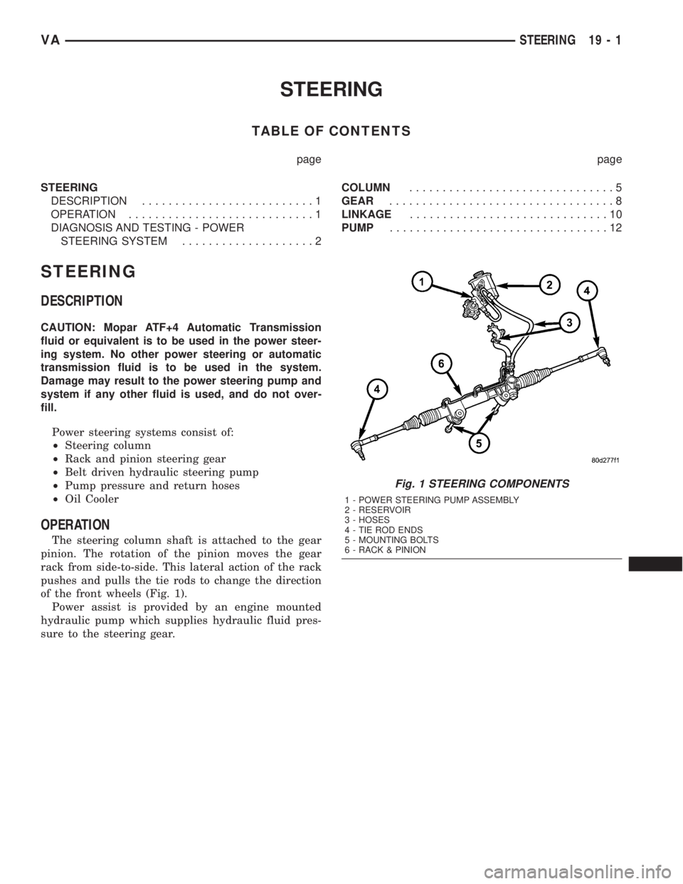
of the front wheels (Fig. 1).
Power assist is provided by an engine mounted
hydraulic pump which supplies hydraulic fluid pres-
sure to the steering gear.
Fig. 1 STEERING COMPONENTS
1 - POWER STEERING PUMP ASSEMBLY
2 - RESERVOIR
3 - HOSES
4 - TIE ROD ENDS
5 - MOUNTING BOLTS
6 - RACK & PINION
VASTEERING 19 - 1
Page 880 of 1232
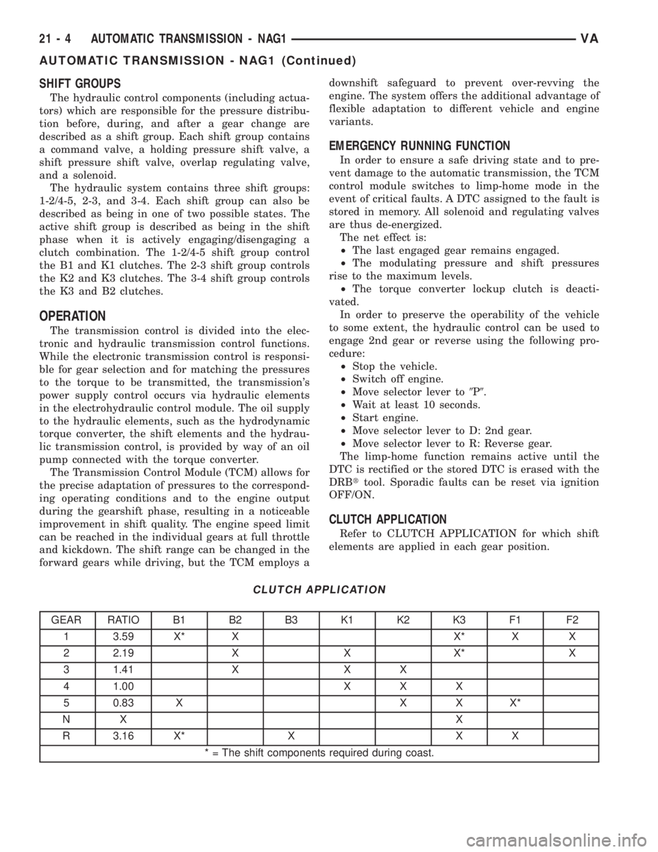
SHIFT GROUPS
The hydraulic control components (including actua-
tors) which are responsible for the pressure distribu-
tion before, during, and after a gear change are
described as a shift group. Each shift group contains
a command valve, a holding pressure shift valve, a
shift pressure shift valve, overlap regulating valve,
and a solenoid.
The hydraulic system contains three shift groups:
1-2/4-5, 2-3, and 3-4. Each shift group can also be
described as being in one of two possible states. The
active shift group is described as being in the shift
phase when it is actively engaging/disengaging a
clutch combination. The 1-2/4-5 shift group control
the B1 and K1 clutches. The 2-3 shift group controls
the K2 and K3 clutches. The 3-4 shift group controls
the K3 and B2 clutches.
OPERATION
The transmission control is divided into the elec-
tronic and hydraulic transmission control functions.
While the electronic transmission control is responsi-
ble for gear selection and for matching the pressures
to the torque to be transmitted, the transmission's
power supply control occurs via hydraulic elements
in the electrohydraulic control module. The oil supply
to the hydraulic elements, such as the hydrodynamic
torque converter, the shift elements and the hydrau-
lic transmission control, is provided by way of an oil
pump connected with the torque converter.
The Transmission Control Module (TCM) allows for
the precise adaptation of pressures to the correspond-
ing operating conditions and to the engine output
during the gearshift phase, resulting in a noticeable
improvement in shift quality. The engine speed limit
can be reached in the individual gears at full throttle
and kickdown. The shift range can be changed in the
forward gears while driving, but the TCM employs adownshift safeguard to prevent over-revving the
engine. The system offers the additional advantage of
flexible adaptation to different vehicle and engine
variants.
EMERGENCY RUNNING FUNCTION
In order to ensure a safe driving state and to pre-
vent damage to the automatic transmission, the TCM
control module switches to limp-home mode in the
event of critical faults. A DTC assigned to the fault is
stored in memory. All solenoid and regulating valves
are thus de-energized.
The net effect is:
²The last engaged gear remains engaged.
²The modulating pressure and shift pressures
rise to the maximum levels.
²The torque converter lockup clutch is deacti-
vated.
In order to preserve the operability of the vehicle
to some extent, the hydraulic control can be used to
engage 2nd gear or reverse using the following pro-
cedure:
²Stop the vehicle.
²Switch off engine.
²Move selector lever to9P9.
²Wait at least 10 seconds.
²Start engine.
²Move selector lever to D: 2nd gear.
²Move selector lever to R: Reverse gear.
The limp-home function remains active until the
DTC is rectified or the stored DTC is erased with the
DRBttool. Sporadic faults can be reset via ignition
OFF/ON.
CLUTCH APPLICATION
Refer to CLUTCH APPLICATION for which shift
elements are applied in each gear position.
CLUTCH APPLICATION
GEAR RATIO B1 B2 B3 K1 K2 K3 F1 F2
1 3.59 X* X X* X X
2 2.19 X X X* X
3 1.41 X X X
4 1.00 X X X
5 0.83 X X X X*
NX X
R 3.16 X* X X X
* = The shift components required during coast.
21 - 4 AUTOMATIC TRANSMISSION - NAG1VA
AUTOMATIC TRANSMISSION - NAG1 (Continued)
Page 907 of 1232
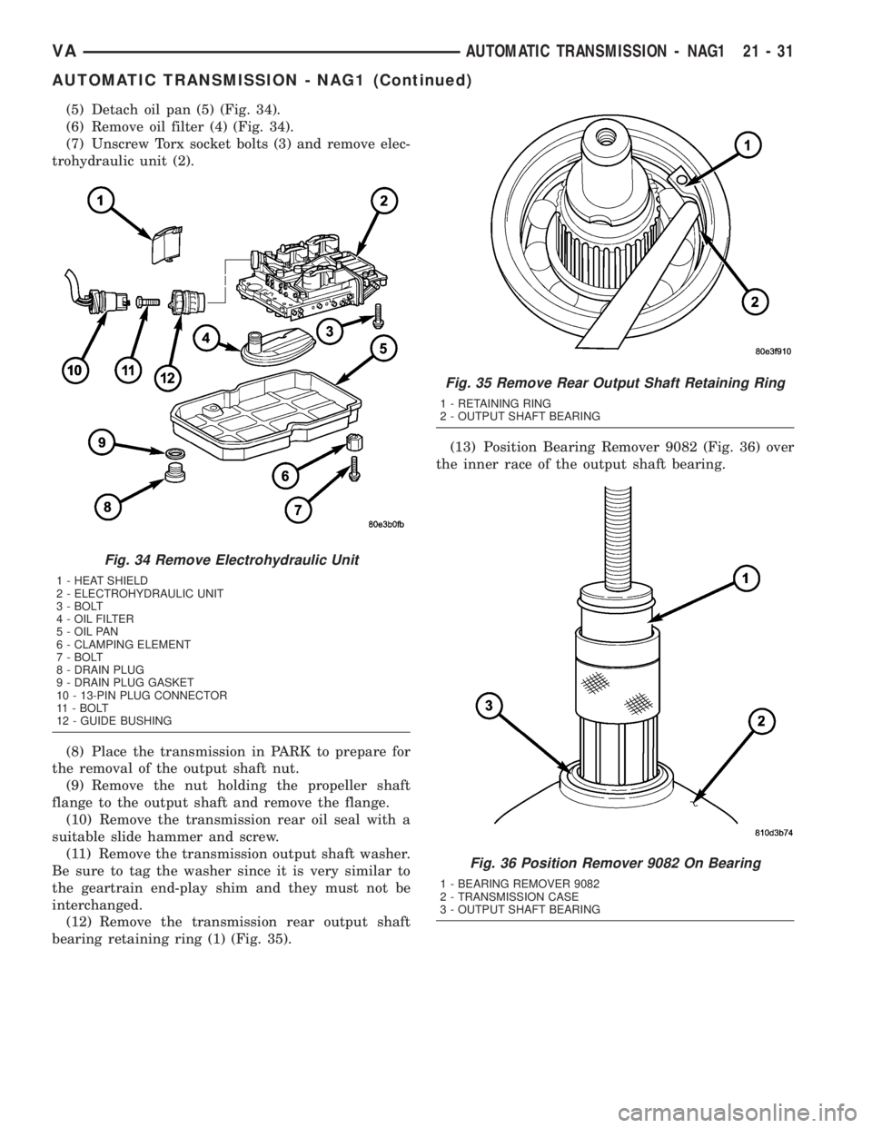
(5) Detach oil pan (5) (Fig. 34).
(6) Remove oil filter (4) (Fig. 34).
(7) Unscrew Torx socket bolts (3) and remove elec-
trohydraulic unit (2).
(8) Place the transmission in PARK to prepare for
the removal of the output shaft nut.
(9) Remove the nut holding the propeller shaft
flange to the output shaft and remove the flange.
(10) Remove the transmission rear oil seal with a
suitable slide hammer and screw.
(11) Remove the transmission output shaft washer.
Be sure to tag the washer since it is very similar to
the geartrain end-play shim and they must not be
interchanged.
(12) Remove the transmission rear output shaft
bearing retaining ring (1) (Fig. 35).(13) Position Bearing Remover 9082 (Fig. 36) over
the inner race of the output shaft bearing.
Fig. 34 Remove Electrohydraulic Unit
1 - HEAT SHIELD
2 - ELECTROHYDRAULIC UNIT
3 - BOLT
4 - OIL FILTER
5 - OIL PAN
6 - CLAMPING ELEMENT
7 - BOLT
8 - DRAIN PLUG
9 - DRAIN PLUG GASKET
10 - 13-PIN PLUG CONNECTOR
11 - BOLT
12 - GUIDE BUSHING
Fig. 35 Remove Rear Output Shaft Retaining Ring
1 - RETAINING RING
2 - OUTPUT SHAFT BEARING
Fig. 36 Position Remover 9082 On Bearing
1 - BEARING REMOVER 9082
2 - TRANSMISSION CASE
3 - OUTPUT SHAFT BEARING
VAAUTOMATIC TRANSMISSION - NAG1 21 - 31
AUTOMATIC TRANSMISSION - NAG1 (Continued)
Page 979 of 1232
(4) Actuate the service brake. Start engine and let
it run at idle speed in selector lever position9P9.
(5) Shift through the transmission modes several
times with the vehicle stationary and the engine
idling
(6) Warm up the transmission, wait at least 2 min-
utes and check the oil level with the engine running.
Push the Oil Dipstick 8863A in up to the stop on the
electrohydraulic unit and pull out again, read off oil
level, repeat if necessary.
NOTE: The dipstick will protrude from the fill tube
approximately 75mm (3 inches) when installed.
(7) Check transmission oil temperature.
NOTE: The true transmission oil temperature can
only be read by a scan tool in REVERSE or any for-
ward gear position. (Refer to 21 - AUTOMATIC
TRANSMISSION- NAG1/TRANSMISSION TEMPERA-
TURE SENSOR/PARK-NEUTRAL SWITCH - OPERA-
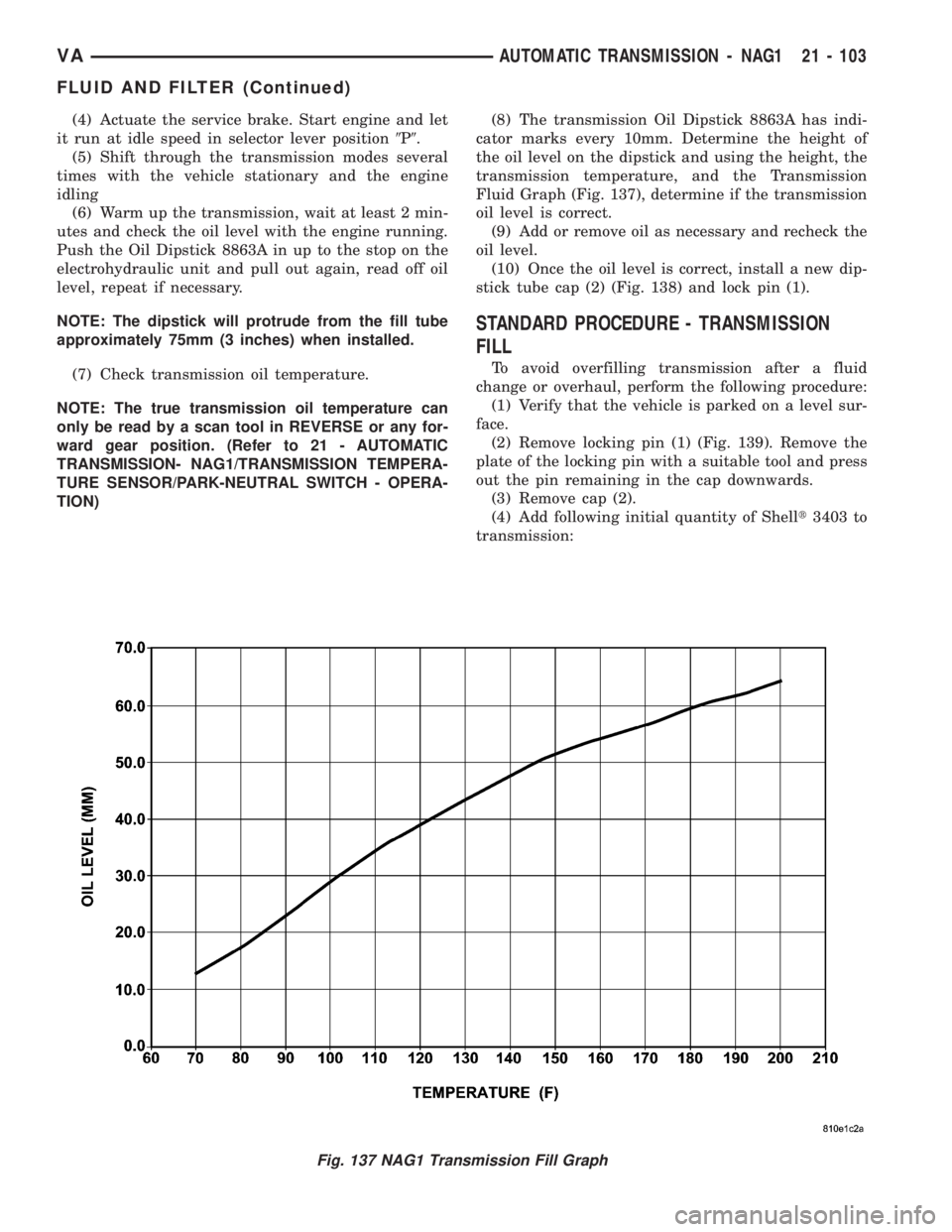
TION)(8) The transmission Oil Dipstick 8863A has indi-
cator marks every 10mm. Determine the height of
the oil level on the dipstick and using the height, the
transmission temperature, and the Transmission
Fluid Graph (Fig. 137), determine if the transmission
oil level is correct.
(9) Add or remove oil as necessary and recheck the
oil level.
(10) Once the oil level is correct, install a new dip-
stick tube cap (2) (Fig. 138) and lock pin (1).
STANDARD PROCEDURE - TRANSMISSION
FILL
To avoid overfilling transmission after a fluid
change or overhaul, perform the following procedure:
(1) Verify that the vehicle is parked on a level sur-
face.
(2) Remove locking pin (1) (Fig. 139). Remove the
plate of the locking pin with a suitable tool and press
out the pin remaining in the cap downwards.
(3) Remove cap (2).
(4) Add following initial quantity of Shellt3403 to
transmission:
Fig. 137 NAG1 Transmission Fill Graph
VAAUTOMATIC TRANSMISSION - NAG1 21 - 103
FLUID AND FILTER (Continued)
Page 980 of 1232
(a) If only fluid and filter were changed, add5.0
L (10.6 pts.)of transmission fluid to transmission.
(b) If transmission was completely overhauled,
torque converter was replaced or drained, and
cooler was flushed, add7.7 L (16.3 pts.)of trans-
mission fluid to transmission.
(5) Check the transmission fluid (Refer to 21 -
TRANSMISSION/AUTOMATIC - NAG1/FLUID -
STANDARD PROCEDURE) and adjust as required.
STANDARD PROCEDURE - FLUID/FILTER
SERVICE
(1) Run the engine until the transmission oil
reaches operating temperature.
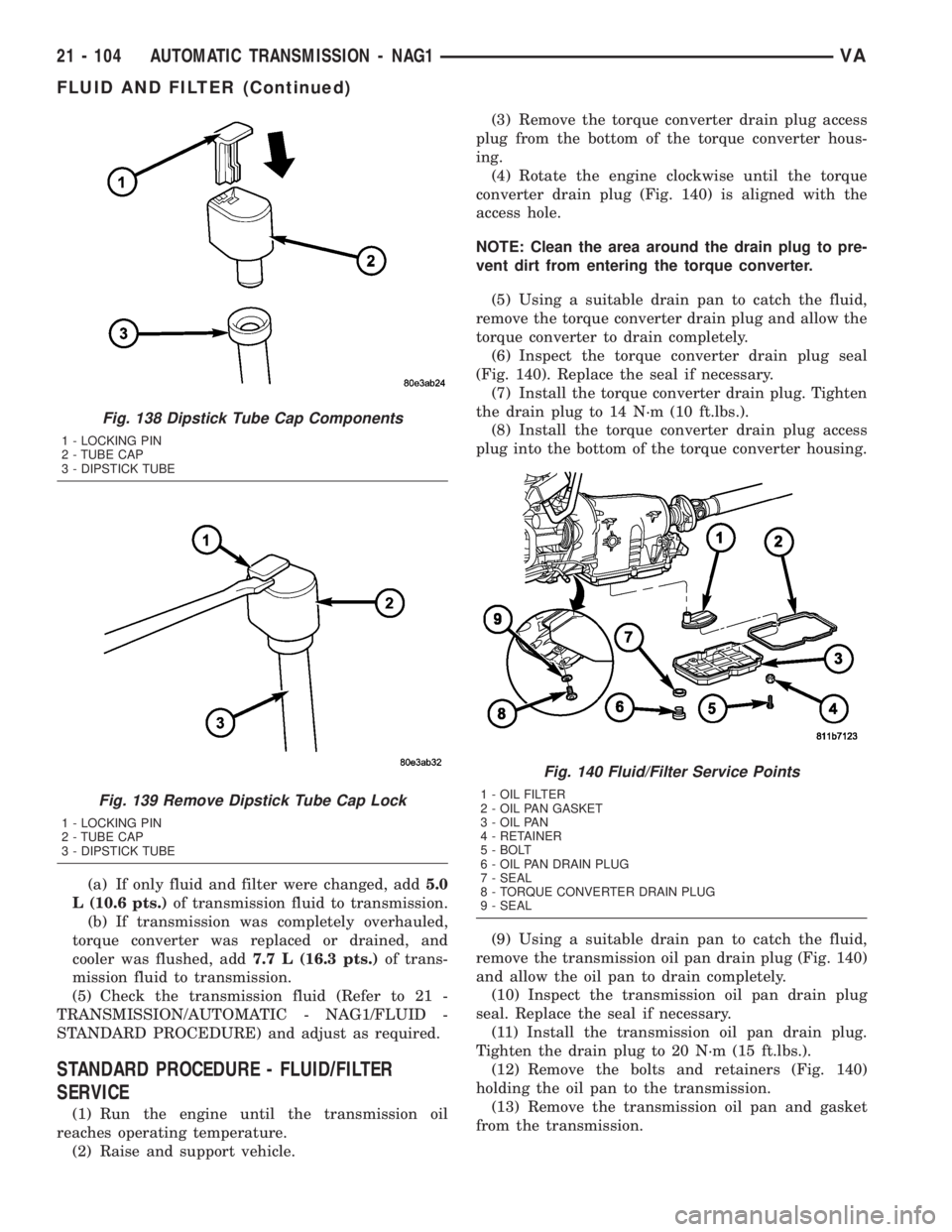
(2) Raise and support vehicle.(3) Remove the torque converter drain plug access
plug from the bottom of the torque converter hous-
ing.
(4) Rotate the engine clockwise until the torque
converter drain plug (Fig. 140) is aligned with the
access hole.
NOTE: Clean the area around the drain plug to pre-
vent dirt from entering the torque converter.
(5) Using a suitable drain pan to catch the fluid,
remove the torque converter drain plug and allow the
torque converter to drain completely.
(6) Inspect the torque converter drain plug seal
(Fig. 140). Replace the seal if necessary.
(7) Install the torque converter drain plug. Tighten
the drain plug to 14 N´m (10 ft.lbs.).
(8) Install the torque converter drain plug access
plug into the bottom of the torque converter housing.
(9) Using a suitable drain pan to catch the fluid,
remove the transmission oil pan drain plug (Fig. 140)
and allow the oil pan to drain completely.
(10) Inspect the transmission oil pan drain plug
seal. Replace the seal if necessary.
(11) Install the transmission oil pan drain plug.
Tighten the drain plug to 20 N´m (15 ft.lbs.).
(12) Remove the bolts and retainers (Fig. 140)
holding the oil pan to the transmission.
(13) Remove the transmission oil pan and gasket
from the transmission.
Fig. 138 Dipstick Tube Cap Components
1 - LOCKING PIN
2 - TUBE CAP
3 - DIPSTICK TUBE
Fig. 139 Remove Dipstick Tube Cap Lock
1 - LOCKING PIN
2 - TUBE CAP
3 - DIPSTICK TUBE
Fig. 140 Fluid/Filter Service Points
1 - OIL FILTER
2 - OIL PAN GASKET
3 - OIL PAN
4 - RETAINER
5 - BOLT
6 - OIL PAN DRAIN PLUG
7 - SEAL
8 - TORQUE CONVERTER DRAIN PLUG
9 - SEAL
21 - 104 AUTOMATIC TRANSMISSION - NAG1VA
FLUID AND FILTER (Continued)