2005 MERCEDES-BENZ SPRINTER oil change
[x] Cancel search: oil changePage 202 of 1232
FRONT FOG LAMPS
Vehicles equipped with optional front fog lamps
have a front fog lamp relay installed in a relay
bracket located below the forward edge of the driver
side front seat cushion within the driver side front
seat riser, a fog lamp switch installed in the cluster
bezel on the instrument panel outboard of the steer-
ing column, and a fog lamp bulb installed in each of
the two front lamp units. The front fog lamps have a
path to ground at all times through their connection
to the vehicle wire harness. The headlamp switch cir-
cuitry of the left (lighting) control stalk of the multi-
function switch controls front fog lamp operation by
providing battery current to the front fog lamp relay
only when the low beam headlamps are selected. The
fog lamp switch controls front fog lamp operation by
energizing or de-energizing the front fog lamp relay
control coil.
HAZARD WARNING LAMPS
With the hazard switch in the On position, the
hazard switch button illuminates and the right and
left turn signal indicators as well as the right and
left turn signal lamps begin to flash on and off. When
the hazard warning system is activated, the hazard
switch circuitry within the multi-function switch and
the wipers, turn signals and engine start control
module electronic circuitry within the fuse block will
repeatedly energize and de-energize the turn signal
relay located in the fuse block. The turn signal relay
switches battery current from a fused B(+) fuse in
the fuse block to the turn signal indicators and the
turn signal lamps. The flashing of the hazard switch
button illumination lamp is also controlled by the
output from the turn signal relay.
HEADLAMPS
The headlamp system includes the exterior lighting
switches integral to the left (lighting) control stalk of
the multi-function switch as well as the low and high
beam bulbs installed in the right and left front lamp
units (Fig. 1). The headlamp bulbs have a path to
ground at all times through the vehicle wire harness.
The exterior lighting switches control headlamp oper-
ation by providing battery current to the selected low
or high beam bulbs. Each front lamp unit includes
two integral adjustment screws to be used for static
horizontal and vertical aiming of the headlamp beam
reflectors.
HEADLAMP LEVELING
The headlamp leveling system includes a leveling
actuator motor integral to each front lamp unit, and
a rotary thumbwheel actuated headlamp leveling
switch in the cluster bezel on the instrument panel
outboard of the steering column. The headlamp lev-eling system allows the headlamp beam reflectors to
be adjusted to one of four vertical positions to com-
pensate for changes in inclination caused by the load-
ing of the vehicle suspension. The actuator motors
are mechanically connected through an integral
pushrod to an adjustable headlamp reflector. The
headlamp leveling switch is a resistor multiplexed
unit that provides one of four voltage outputs to the
headlamp leveling motors. The headlamp leveling
motors will move the headlamps to the selected posi-
tion based upon the voltage input received from the
switch. The headlamp leveling motors and switch
have a path to ground at all times. The headlamp
leveling components operate on battery current
received through the park lamps circuit so that the
system will only operate when the exterior lighting is
turned on.
PARK LAMPS
The park lamps system includes the exterior light-
ing switches integral to the left (lighting) control
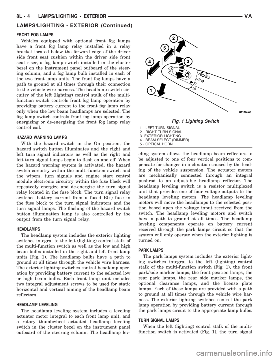
stalk of the multi-function switch (Fig. 1), the front
park/side marker lamps, the front position lamps, the
rear park lamps, the rear side marker lamps, the
optional clearance lamps, and the license plate
lamps. Each of these lamps are provided with a path
to ground at all times through the vehicle wire har-
ness. The exterior lighting switches control the park
lamp operation by providing battery current through
the park lamps circuit to the appropriate lamp bulbs.
TURN SIGNAL LAMPS
When the left (lighting) control stalk of the multi-
function switch is activated (Fig. 1), the turn signal
Fig. 1 Lighting Switch
1 - LEFT TURN SIGNAL
2 - RIGHT TURN SIGNAL
3 -EXTERIOR LIGHTING
4 - BEAM SELECT (DIMMER)
5 - OPTICAL HORN
8L - 4 LAMPS/LIGHTING - EXTERIORVA
LAMPS/LIGHTING - EXTERIOR (Continued)
Page 317 of 1232
8W-02 COMPONENT INDEX
Component Page
A/C Auxiliary Fan Relay................ 8W-42
A/C Auxiliary Fan..................... 8W-42
A/C Compressor Clutch................. 8W-42
A/C Control Module-Roof................ 8W-42
A/C Fan Switch....................... 8W-42
A/C Switch-Roof...................... 8W-42
Accelerator Pedal Position Sensor......... 8W-30
Air Outlet Temperature Sensor........... 8W-42
Airbag Control Module................. 8W-43
Airbag Squibs........................ 8W-43
Ambient Temperature Sensor............ 8W-42
Ash Receiver Lamp.................... 8W-44
Automatic Temperature Control Module.... 8W-42
Auxiliary Heater Relay................. 8W-42
Auxiliary Heater Switch................ 8W-42
Battery Relay-Auxiliary................ 8W-20
Batteries............................ 8W-20
Beam Select Switch.................... 8W-50
Blower Motors........................ 8W-42
Body Plug Connector................... 8W-11
Boost Pressure Sensor.................. 8W-30
Boost Pressure Solenoid................ 8W-30
Brake Fluid Level Switch............... 8W-35
Brake Lamp Switch.................... 8W-35
Brake Wear Sensors................... 8W-35
Cabin Heater Assembly................. 8W-42
Cabin Heater Control Module............ 8W-42
Camshaft Position Sensor............... 8W-30
Center High Mounted Stop Lamp......... 8W-51
Central Timer Module.................. 8W-45
Cigar Lighter Lamp................... 8W-44
Cigar Lighter......................... 8W-41
Circulation Pump Diode................ 8W-42
Circulation Pump Relay................ 8W-42
Circulation Pump..................... 8W-42
Clockspring....................... 8W-41, 43
Contact Switch Door-Tailgate............ 8W-44
Controller Antilock Brake............... 8W-35
Courtesy Lamps...................... 8W-44
Crankcase Heater..................... 8W-30
Crankshaft Position Sensor.............. 8W-30
Ctel Antenna Connector................ 8W-55
Ctel Connector..................... 8W-47, 55
Cylinder Lock Switch-Driver............. 8W-61
D+ Relay No. 1....................... 8W-10
D+ Relay No. 2....................... 8W-11
Data Link Connector................... 8W-18
Daytime Running Lamp Relays........... 8W-50
Differential Lock Solenoid Valve.......... 8W-31
Dome Lamp.......................... 8W-44
Door Jamb Switches................... 8W-44
Door Lock Motor/Ajar Switch Assemblies . . . 8W-61Component Page
Dosing Pump......................... 8W-42
EGR Valve........................... 8W-30
Engine Control Module................. 8W-30
Engine Control Relay.................. 8W-31
Engine Coolant Level Switch............. 8W-30
Engine Coolant Temperature Sensor....... 8W-30
Engine Oil Sensor..................... 8W-30
Evaporator Temperature Sensor.......... 8W-42
Fan Stage 1 Relay..................... 8W-42
Fog Lamp Relay...................... 8W-50
Fog Lamp Switch..................... 8W-50
Fuel Injectors........................ 8W-30
Fuel Level Sensor..................... 8W-30
Fuel Pressure Sensor.................. 8W-30
Fuel Pressure Solenoid................. 8W-30
Fuel Shutdown Solenoid................ 8W-30
Fuel Temperature Sensor............... 8W-30
Fuses............................ 8W-10, 11
Fuse Blocks.......................... 8W-10
Fuse/Relay Block...................... 8W-11
Fused Ignition Switch Run-Start Relay..... 8W-11
Grounds............................ 8W-70
Generator........................... 8W-20
Glow Plug Control Module.............. 8W-30
Glow Plugs.......................... 8W-30
Hazard Warning Switch................ 8W-52
Headlamp Adjust Switch................ 8W-50
Headlamp Assemblies............... 8W-50, 52
Headlamp Switch..................... 8W-50
Heat Exchanger Connector.............. 8W-42
Heat Exchanger Switch................. 8W-42
Heated Seat Modules.................. 8W-63
Heated Seat Switches.................. 8W-63
Heater Timer-Auxiliary................. 8W-42
Hood Ajar Switch..................... 8W-39
Horn Relay.......................... 8W-41
Horn Switch......................... 8W-41
Horn............................... 8W-41
Ignition Lock Switch................... 8W-40
Ignition Switch....................... 8W-10
Instrument Cluster.................... 8W-40
Instrument Panel Socket................ 8W-40
Intake Air Temperature Sensor........... 8W-30
Interior Lamps....................... 8W-44
Interior Light Switches................. 8W-44
Interior Lighting Connector.............. 8W-44
Intrusion Sensors..................... 8W-39
Kickdown Switch...................... 8W-30
Lamp Relays......................... 8W-50
License Plate Lamps................... 8W-51
Locker Switches...................... 8W-31
Low Fuel Pressure Sensor............... 8W-30
VA8W-02 COMPONENT INDEX 8W - 02 - 1
Page 628 of 1232
Component Page
Differential Lock Solenoid Valve........ 8W-80-29
Dome Lamp....................... 8W-80-29
Door Lock Motor/Ajar Switch
Assembly-Driver C1............... 8W-80-30
Door Lock Motor/Ajar Switch
Assembly-Driver C2............... 8W-80-30
Door Lock Motor/Ajar Switch
Assembly-Left Sliding C1........... 8W-80-30
Door Lock Motor/Ajar Switch
Assembly-Left Sliding C2........... 8W-80-30
Door Lock Motor/Ajar Switch
Assembly-Passenger C1............ 8W-80-30
Door Lock Motor/Ajar Switch
Assembly-Passenger C2............ 8W-80-31
Door Lock Motor/Ajar Switch
Assembly-Rear C1................ 8W-80-31
Door Lock Motor/Ajar Switch
Assembly-Rear C2................ 8W-80-31
Door Lock Motor/Ajar Switch
Assembly-Right Sliding C1.......... 8W-80-31
Door Lock Motor/Ajar Switch
Assembly-Right Sliding C2.......... 8W-80-31
Dosing Pump...................... 8W-80-32
EGR Valve........................ 8W-80-32
Engine Control Module C1............ 8W-80-32
Engine Control Module C2............ 8W-80-32
Engine Control Module C3............ 8W-80-33
Engine Control Module C4............ 8W-80-33
Engine Control Module C5............ 8W-80-34
Engine Coolant Level Switch.......... 8W-80-34
Engine Coolant Temperature Sensor.... 8W-80-34
Engine Oil Sensor................... 8W-80-34
Evaporator Temperature Sensor........ 8W-80-35
Fog Lamp Switch................... 8W-80-35
Fuel Injector No. 1.................. 8W-80-35
Fuel Injector No. 2.................. 8W-80-35
Fuel Injector No. 3.................. 8W-80-35
Fuel Injector No. 4.................. 8W-80-36
Fuel Injector No. 5.................. 8W-80-36
Fuel Level Sensor................... 8W-80-36
Fuel Pressure Sensor................ 8W-80-36
Fuel Pressure Solenoid............... 8W-80-36
Fuel Shutdown Solenoid.............. 8W-80-37
Fuel Temperature Sensor............. 8W-80-37
Fuse Block No. 1 C1................. 8W-80-37
Fuse Block No. 1 C2................. 8W-80-37
Fuse Block No. 1 C3................. 8W-80-38
Fuse Block No. 1 C4................. 8W-80-38
Fuse Block No. 1 C5................. 8W-80-38
Glow Plug Control Module C1......... 8W-80-38
Glow Plug Control Module C2......... 8W-80-39
Headlamp Adjust Switch............. 8W-80-39
Headlamp Assembly-Left............. 8W-80-39
Headlamp Assembly-Right............ 8W-80-40
Heat Exchanger Connector............ 8W-80-40Component Page
Heat Exchanger Switch.............. 8W-80-40
Heated Seat Module-Driver........... 8W-80-40
Heated Seat Module-Passenger........ 8W-80-41
Heated Seat Switch-Driver............ 8W-80-41
Heated Seat Switch-Passenger......... 8W-80-41
Heater Timer-Auxiliary.............. 8W-80-41
Hood Ajar Switch................... 8W-80-42
Horn............................. 8W-80-42
Horn (VTSS)....................... 8W-80-42
Horn-Switch....................... 8W-80-42
Ignition Lock Switch................. 8W-80-43
Instrument Cluster C1............... 8W-80-43
Instrument Cluster C2............... 8W-80-43
Instrument Panel Socket............. 8W-80-44
Intake Air Temperature Sensor........ 8W-80-44
Interior Lamp No. 1................. 8W-80-44
Interior Lamp No. 2................. 8W-80-44
Interior Lamp No. 3................. 8W-80-44
Interior Lamp No. 4................. 8W-80-45
Interior Lamp No. 5................. 8W-80-45
Interior Lamp-Left.................. 8W-80-45
Interior Lamp-Middle Front........... 8W-80-45
Interior Lamp-Middle Rear........... 8W-80-46
Interior Lamp-Rear No. 1............. 8W-80-46
Interior Lamp-Rear No. 2............. 8W-80-46
Interior Lamp-Right................. 8W-80-47
Interior Light Switch................ 8W-80-47
Interior Light Switch-Driver........... 8W-80-47
Interior Light Switch-Passenger........ 8W-80-47
Interior Light Switch-Rear............ 8W-80-48
Interior Lighting Connector........... 8W-80-48
Intrusion Sensor No. 1............... 8W-80-48
Intrusion Sensor No. 2............... 8W-80-48
Intrusion Sensor No. 3............... 8W-80-48
Kick Down Switch.................. 8W-80-49
License Plate Lamp No. 1............. 8W-80-49
License Plate Lamp No. 2............. 8W-80-49
Locker Switch No. 1................. 8W-80-49
Locker Switch No. 2................. 8W-80-49
Low Fuel Pressure Sensor............ 8W-80-50
Map/Reading Lamp Switch............ 8W-80-50
Marker Lamp Connector............. 8W-80-50
Marker Lamp No. 1-Left Front......... 8W-80-50
Marker Lamp No. 1-Right Front....... 8W-80-50
Marker Lamp No. 2-Left Front......... 8W-80-51
Marker Lamp No. 2-Right Front....... 8W-80-51
Marker Lamp-Left Center............ 8W-80-51
Marker Lamp-Left Rear.............. 8W-80-51
Marker Lamp-Right Center........... 8W-80-51
Marker Lamp-Right Rear............. 8W-80-52
Mass Air Flow Sensor................ 8W-80-52
Master Door Lock Switch............. 8W-80-52
Metering Pump..................... 8W-80-52
Microphone Connector............... 8W-80-52
8W - 80 - 2 8W-80 CONNECTOR PIN-OUTSVA
Page 749 of 1232
DESCRIPTION N´m Ft. Lbs. In. Lbs.
Nut-Connection of Circuit
506-53
Alternator
Bolt-Generator to Timing
Case Cover20 15 -
Bolt-Generator to Cooler
Housing6-53
Bolt-Cooler Housing of
Generator to Crankcase20 - 177
Nut-B+ Circuit to
Generator13-18 - 115-159
Nut-D+ Circuit to
Generator5-44
Nut-Collar to V-Belt Pulley 80 59 -
Oil Pump
Bolt-Oil Pump to
Crankcase18
- 133
Bolt-Oil Pipe to Crankshaft
Bearing Cap8-70
Oil Filter
Screw Cap to Oil Filter 25 18.5 -
Oil Cooling System
Bolt-Oil-Water Heat
Exchanger to Timing
Cover Case15 - 133
Oil Level Pressure
Bolt-Dip Stick Guide Tube
to Cylinder Head14 - 123
Bolt-Oil Level Sensor to
Oil Pan14 - 123
Coolant Pre-Heater
Coolant Pre-Heater in
Engine Block35 26 -
Engine Cooling General
Bolt-Belt Pulley to Coolant
Pump8-35 6 - 26 -
Bolt-Coolant Pump to
Timing Case Cover 6m/8m14/20 10 - 15 -
Bolt-Thremostat Housing
to Cylinder Head9-80
Coolant Drain Plug to
Crankcase30 22 -
Engine Suspension, Engine Mount, Engine Bracket
Bolt-Engine Bracket to
Crankcase (2 stage,
torque, torque angle)20/90É 15 -
VAENGINE 9 - 11
ENGINE (Continued)
Page 782 of 1232
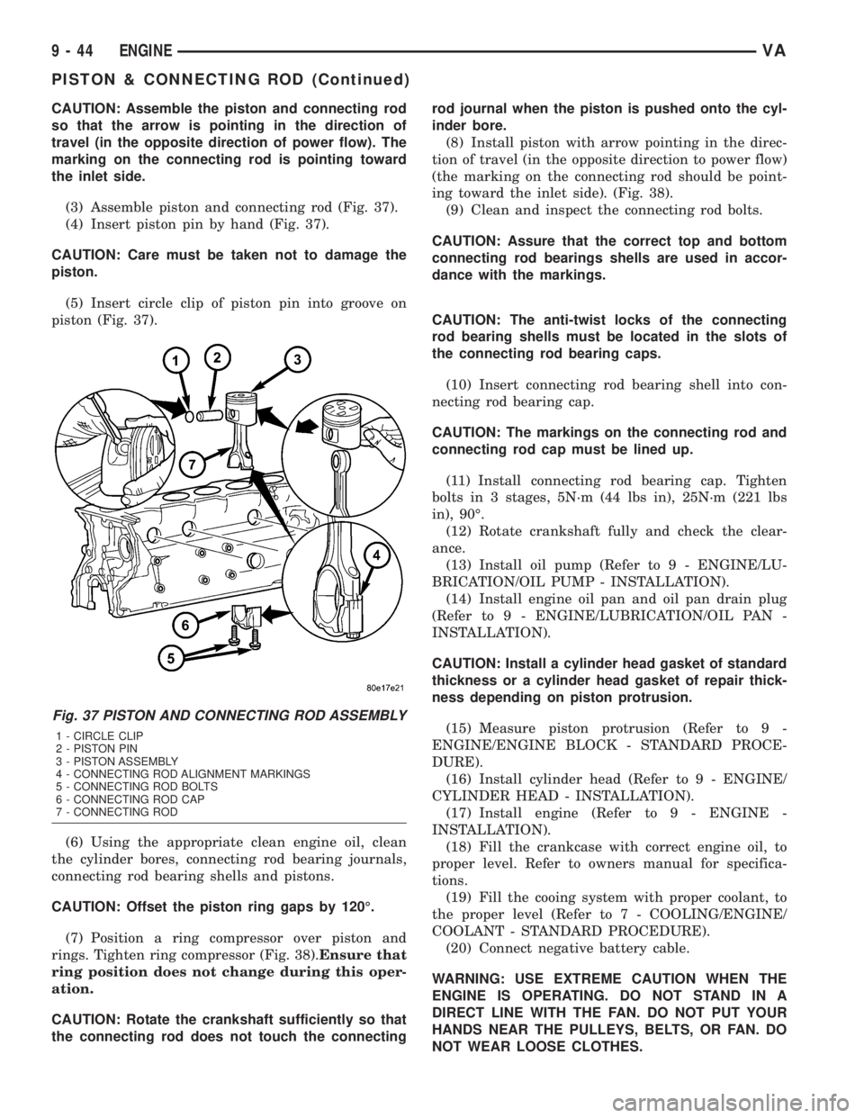
CAUTION: Assemble the piston and connecting rod
so that the arrow is pointing in the direction of
travel (in the opposite direction of power flow). The
marking on the connecting rod is pointing toward
the inlet side.
(3) Assemble piston and connecting rod (Fig. 37).
(4) Insert piston pin by hand (Fig. 37).
CAUTION: Care must be taken not to damage the
piston.
(5) Insert circle clip of piston pin into groove on
piston (Fig. 37).
(6) Using the appropriate clean engine oil, clean
the cylinder bores, connecting rod bearing journals,
connecting rod bearing shells and pistons.
CAUTION: Offset the piston ring gaps by 120É.
(7) Position a ring compressor over piston and
rings. Tighten ring compressor (Fig. 38).Ensure that
ring position does not change during this oper-
ation.
CAUTION: Rotate the crankshaft sufficiently so that
the connecting rod does not touch the connectingrod journal when the piston is pushed onto the cyl-
inder bore.
(8) Install piston with arrow pointing in the direc-
tion of travel (in the opposite direction to power flow)
(the marking on the connecting rod should be point-
ing toward the inlet side). (Fig. 38).
(9) Clean and inspect the connecting rod bolts.
CAUTION: Assure that the correct top and bottom
connecting rod bearings shells are used in accor-
dance with the markings.
CAUTION: The anti-twist locks of the connecting
rod bearing shells must be located in the slots of
the connecting rod bearing caps.
(10) Insert connecting rod bearing shell into con-
necting rod bearing cap.
CAUTION: The markings on the connecting rod and
connecting rod cap must be lined up.
(11) Install connecting rod bearing cap. Tighten
bolts in 3 stages, 5N´m (44 lbs in), 25N´m (221 lbs
in), 90É.
(12) Rotate crankshaft fully and check the clear-
ance.
(13) Install oil pump (Refer to 9 - ENGINE/LU-
BRICATION/OIL PUMP - INSTALLATION).
(14) Install engine oil pan and oil pan drain plug
(Refer to 9 - ENGINE/LUBRICATION/OIL PAN -
INSTALLATION).
CAUTION: Install a cylinder head gasket of standard
thickness or a cylinder head gasket of repair thick-
ness depending on piston protrusion.
(15) Measure piston protrusion (Refer to 9 -
ENGINE/ENGINE BLOCK - STANDARD PROCE-
DURE).
(16) Install cylinder head (Refer to 9 - ENGINE/
CYLINDER HEAD - INSTALLATION).
(17) Install engine (Refer to 9 - ENGINE -
INSTALLATION).
(18) Fill the crankcase with correct engine oil, to
proper level. Refer to owners manual for specifica-
tions.
(19) Fill the cooing system with proper coolant, to
the proper level (Refer to 7 - COOLING/ENGINE/
COOLANT - STANDARD PROCEDURE).
(20) Connect negative battery cable.
WARNING: USE EXTREME CAUTION WHEN THE
ENGINE IS OPERATING. DO NOT STAND IN A
DIRECT LINE WITH THE FAN. DO NOT PUT YOUR
HANDS NEAR THE PULLEYS, BELTS, OR FAN. DO
NOT WEAR LOOSE CLOTHES.
Fig. 37 PISTON AND CONNECTING ROD ASSEMBLY
1 - CIRCLE CLIP
2 - PISTON PIN
3 - PISTON ASSEMBLY
4 - CONNECTING ROD ALIGNMENT MARKINGS
5 - CONNECTING ROD BOLTS
6 - CONNECTING ROD CAP
7 - CONNECTING ROD
9 - 44 ENGINEVA
PISTON & CONNECTING ROD (Continued)
Page 784 of 1232
PISTON RINGS
STANDARD PROCEDURE - PISTON RING
FITTING
(1) Carefully clean the carbon from all ring
grooves. Oil drain openings in the oil ring groove and
pin boss must be clear. DO NOT remove metal from
the grooves or lands. This will change ring-to-groove
clearances and will damage the ring-to-land seating.
(2) Be sure the piston ring grooves are free of
nicks and burrs.
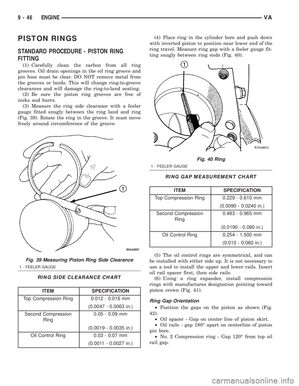
(3) Measure the ring side clearance with a feeler
gauge fitted snugly between the ring land and ring
(Fig. 39). Rotate the ring in the groove. It must move
freely around circumference of the groove.
RING SIDE CLEARANCE CHART
ITEM SPECIFICATION
Top Compression Ring 0.012 - 0.016 mm
(0.0047 - 0.0063 in.)
Second Compression
Ring0.05 - 0.09 mm
(0.0019 - 0.0035 in.)
Oil Control Ring 0.03 - 0.07 mm
(0.0011 - 0.0027 in.)(4) Place ring in the cylinder bore and push down
with inverted piston to position near lower end of the
ring travel. Measure ring gap with a feeler gauge fit-
ting snugly between ring ends (Fig. 40).
RING GAP MEASUREMENT CHART
ITEM SPECIFICATION
Top Compression Ring 0.229 - 0.610 mm
(0.0090 - 0.0240 in.)
Second Compression
Ring0.483 - 0.965 mm
(0.0190 - 0.080 in.)
Oil Control Ring 0.254 - 1.500 mm
(0.010 - 0.060 in.)
(5) The oil control rings are symmetrical, and can
be installed with either side up. It is not necessary to
use a tool to install the upper and lower rails. Insert
oil rail spacer first, then side rails.
(6) Using a ring expander, install compression
rings with manufactures designation pointing toward
piston crown (Fig. 41).
Ring Gap Orientation
²Position the gaps on the piston as shown (Fig.
42).
²Oil spacer - Gap on center line of piston skirt.
²Oil rails - gap 180É apart on centerline of piston
pin bore.
²No. 2 Compression ring - Gap 120É from top oil
rail gap.
Fig. 39 Measuring Piston Ring Side Clearance
1 - FEELER GAUGE
Fig. 40 Ring
1 - FEELER GAUGE
9 - 46 ENGINEVA
Page 793 of 1232
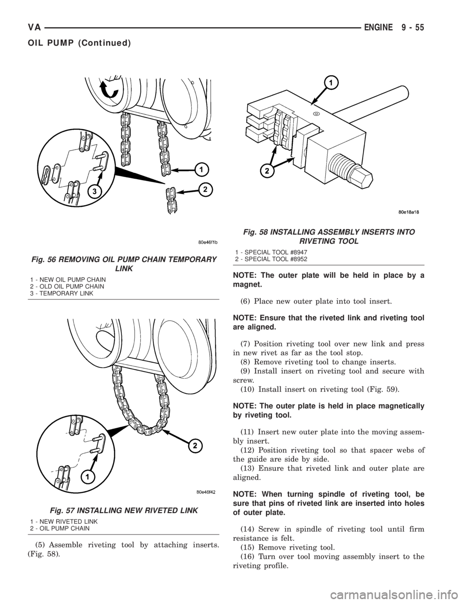
(5) Assemble riveting tool by attaching inserts.
(Fig. 58).NOTE: The outer plate will be held in place by a
magnet.
(6) Place new outer plate into tool insert.
NOTE: Ensure that the riveted link and riveting tool
are aligned.
(7) Position riveting tool over new link and press
in new rivet as far as the tool stop.
(8) Remove riveting tool to change inserts.
(9) Install insert on riveting tool and secure with
screw.
(10) Install insert on riveting tool (Fig. 59).
NOTE: The outer plate is held in place magnetically
by riveting tool.
(11) Insert new outer plate into the moving assem-
bly insert.
(12) Position riveting tool so that spacer webs of
the guide are side by side.
(13) Ensure that riveted link and outer plate are
aligned.
NOTE: When turning spindle of riveting tool, be
sure that pins of riveted link are inserted into holes
of outer plate.
(14) Screw in spindle of riveting tool until firm
resistance is felt.
(15) Remove riveting tool.
(16) Turn over tool moving assembly insert to the
riveting profile.
Fig. 56 REMOVING OIL PUMP CHAIN TEMPORARY
LINK
1 - NEW OIL PUMP CHAIN
2 - OLD OIL PUMP CHAIN
3 - TEMPORARY LINK
Fig. 57 INSTALLING NEW RIVETED LINK
1 - NEW RIVETED LINK
2 - OIL PUMP CHAIN
Fig. 58 INSTALLING ASSEMBLY INSERTS INTO
RIVETING TOOL
1 - SPECIAL TOOL #8947
2 - SPECIAL TOOL #8952
VAENGINE 9 - 55
OIL PUMP (Continued)
Page 794 of 1232
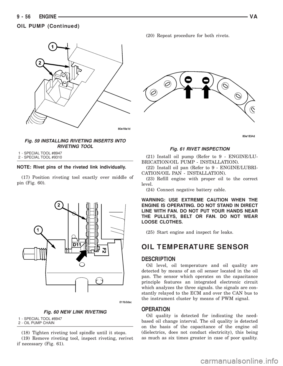
NOTE: Rivet pins of the riveted link individually.
(17) Position riveting tool exactly over middle of
pin (Fig. 60).
(18) Tighten riveting tool spindle until it stops.
(19) Remove riveting tool, inspect riveting, rerivet
if necessary (Fig. 61).(20) Repeat procedure for both rivets.
(21) Install oil pump (Refer to 9 - ENGINE/LU-
BRICATION/OIL PUMP - INSTALLATION).
(22) Install oil pan (Refer to 9 - ENGINE/LUBRI-
CATION/OIL PAN - INSTALLATION).
(23) Refill engine with proper oil to the correct
level.
(24) Connect negative battery cable.
WARNING: USE EXTREME CAUTION WHEN THE
ENGINE IS OPERATING. DO NOT STAND IN DIRECT
LINE WITH FAN. DO NOT PUT YOUR HANDS NEAR
THE PULLEYS, BELT OR FAN. DO NOT WEAR
LOOSE CLOTHES.
(25) Start engine and inspect for leaks.
OIL TEMPERATURE SENSOR
DESCRIPTION
Oil level, oil temperature and oil quality are
detected by means of an oil sensor located in the oil
pan. The sensor which operates on the capacitance
principle features an integrated electronic circuit
which analyzes the three signals. the signals are con-
stantly relayed to the ECM and over the CAN bus to
the instrument cluster by means of PWM signal.
OPERATION
Oil quality is detected for indicating the need-
based oil change interval. The oil quality is detected
on the basis of the capacitance of the engine oil
(dielectrics, does not conduct electricity), this being
as much as six times greater in case of poor quality.
Fig. 59 INSTALLING RIVETING INSERTS INTO
RIVETING TOOL
1 - SPECIAL TOOL #8947
2 - SPECIAL TOOL #9310
Fig. 60 NEW LINK RIVETING
1 - SPECIAL TOOL #8947
2 - OIL PUMP CHAIN
Fig. 61 RIVET INSPECTION
9 - 56 ENGINEVA
OIL PUMP (Continued)