2005 MERCEDES-BENZ SPRINTER change time
[x] Cancel search: change timePage 393 of 1232
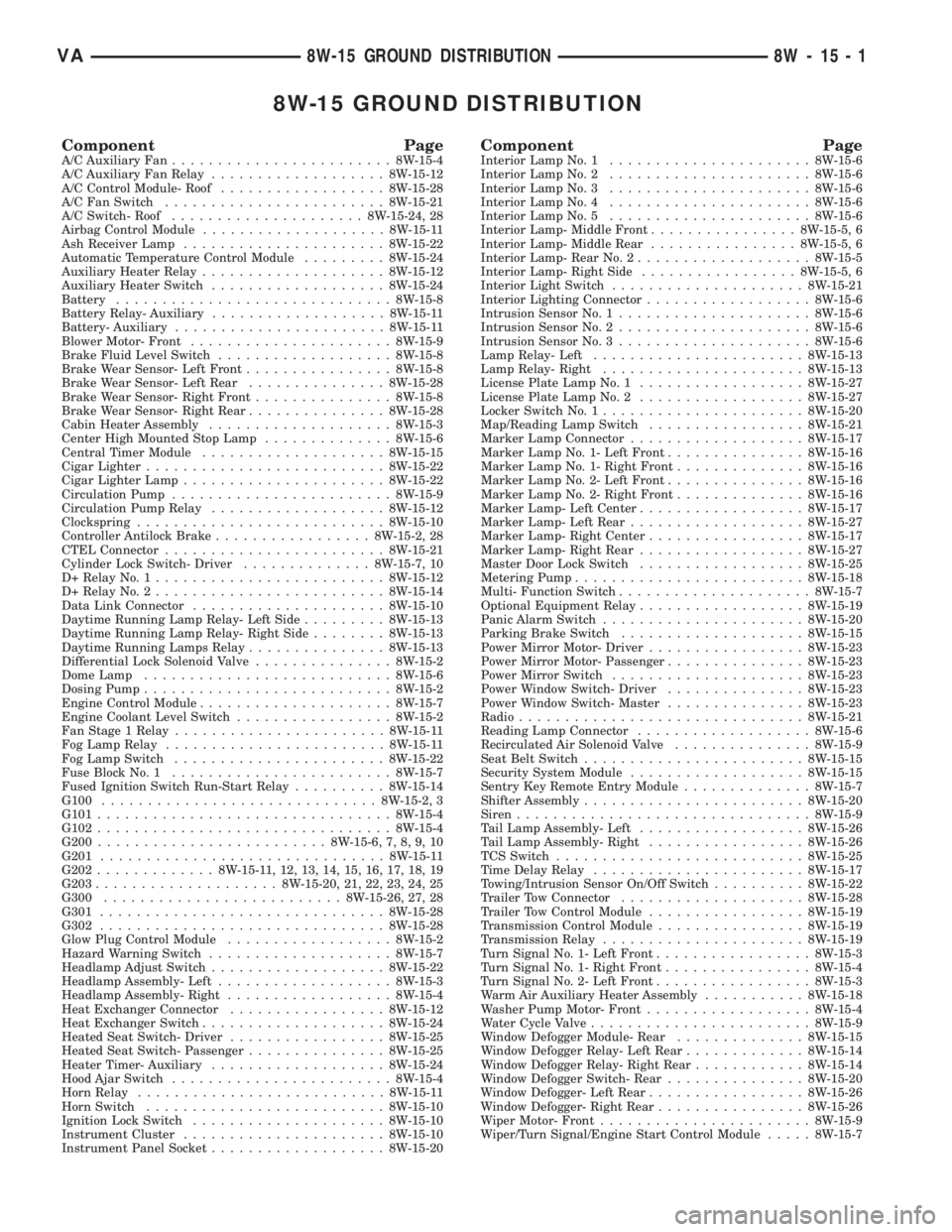
8W-15 GROUND DISTRIBUTION
Component PageA/C Auxiliary Fan........................8W-15-4
A/C Auxiliary Fan Relay...................8W-15-12
A/C Control Module- Roof..................8W-15-28
A/C Fan Switch........................8W-15-21
A/C Switch- Roof.....................8W-15-24, 28
Airbag Control Module....................8W-15-11
Ash Receiver Lamp......................8W-15-22
Automatic Temperature Control Module.........8W-15-24
Auxiliary Heater Relay....................8W-15-12
Auxiliary Heater Switch...................8W-15-24
Battery..............................8W-15-8
Battery Relay- Auxiliary...................8W-15-11
Battery- Auxiliary.......................8W-15-11
Blower Motor- Front......................8W-15-9
Brake Fluid Level Switch...................8W-15-8
Brake Wear Sensor- Left Front................8W-15-8
Brake Wear Sensor- Left Rear...............8W-15-28
Brake Wear Sensor- Right Front...............8W-15-8
Brake Wear Sensor- Right Rear...............8W-15-28
Cabin Heater Assembly....................8W-15-3
Center High Mounted Stop Lamp..............8W-15-6
Central Timer Module....................8W-15-15
Cigar Lighter..........................8W-15-22
Cigar Lighter Lamp......................8W-15-22
Circulation Pump........................8W-15-9
Circulation Pump Relay...................8W-15-12
Clockspring...........................8W-15-10
Controller Antilock Brake.................8W-15-2, 28
CTEL Connector........................8W-15-21
Cylinder Lock Switch- Driver..............8W-15-7, 10
D+ Relay No. 1.........................8W-15-12
D+ Relay No. 2.........................8W-15-14
Data Link Connector.....................8W-15-10
Daytime Running Lamp Relay- Left Side.........8W-15-13
Daytime Running Lamp Relay- Right Side........8W-15-13
Daytime Running Lamps Relay...............8W-15-13
Differential Lock Solenoid Valve...............8W-15-2
Dome Lamp...........................8W-15-6
Dosing Pump...........................8W-15-2
Engine Control Module.....................8W-15-7
Engine Coolant Level Switch.................8W-15-2
Fan Stage 1 Relay.......................8W-15-11
Fog Lamp Relay........................8W-15-11
Fog Lamp Switch.......................8W-15-22
Fuse Block No. 1........................8W-15-7
Fused Ignition Switch Run-Start Relay..........8W-15-14
G100..............................8W-15-2, 3
G101................................8W-15-4
G102................................8W-15-4
G200.........................8W-15-6, 7, 8, 9, 10
G201...............................8W-15-11
G202.............8W-15-11, 12, 13, 14, 15, 16, 17, 18, 19
G203....................8W-15-20, 21, 22, 23, 24, 25
G300..........................8W-15-26, 27, 28
G301...............................8W-15-28
G302...............................8W-15-28
Glow Plug Control Module..................8W-15-2
Hazard Warning Switch....................8W-15-7
Headlamp Adjust Switch...................8W-15-22
Headlamp Assembly- Left...................8W-15-3
Headlamp Assembly- Right..................8W-15-4
Heat Exchanger Connector.................8W-15-12
Heat Exchanger Switch....................8W-15-24
Heated Seat Switch- Driver.................8W-15-25
Heated Seat Switch- Passenger...............8W-15-25
Heater Timer- Auxiliary...................8W-15-24
Hood Ajar Switch........................8W-15-4
Horn Relay...........................8W-15-11
Horn Switch..........................8W-15-10
Ignition Lock Switch.....................8W-15-10
Instrument Cluster......................8W-15-10
Instrument Panel Socket...................8W-15-20Component PageInterior Lamp No. 1......................8W-15-6
Interior Lamp No. 2......................8W-15-6
Interior Lamp No. 3......................8W-15-6
Interior Lamp No. 4......................8W-15-6
Interior Lamp No. 5......................8W-15-6
Interior Lamp- Middle Front................8W-15-5, 6
Interior Lamp- Middle Rear................8W-15-5, 6
Interior Lamp- Rear No. 2...................8W-15-5
Interior Lamp- Right Side.................8W-15-5, 6
Interior Light Switch.....................8W-15-21
Interior Lighting Connector..................8W-15-6
Intrusion Sensor No. 1.....................8W-15-6
Intrusion Sensor No. 2.....................8W-15-6
Intrusion Sensor No. 3.....................8W-15-6
Lamp Relay- Left.......................8W-15-13
Lamp Relay- Right......................8W-15-13
License Plate Lamp No. 1..................8W-15-27
License Plate Lamp No. 2..................8W-15-27
Locker Switch No. 1......................8W-15-20
Map/Reading Lamp Switch.................8W-15-21
Marker Lamp Connector...................8W-15-17
Marker Lamp No. 1- Left Front...............8W-15-16
Marker Lamp No. 1- Right Front..............8W-15-16
Marker Lamp No. 2- Left Front...............8W-15-16
Marker Lamp No. 2- Right Front..............8W-15-16
Marker Lamp- Left Center..................8W-15-17
Marker Lamp- Left Rear...................8W-15-27
Marker Lamp- Right Center.................8W-15-17
Marker Lamp- Right Rear..................8W-15-27
Master Door Lock Switch..................8W-15-25
Metering Pump.........................8W-15-18
Multi- Function Switch.....................8W-15-7
Optional Equipment Relay..................8W-15-19
Panic Alarm Switch......................8W-15-20
Parking Brake Switch....................8W-15-15
Power Mirror Motor- Driver.................8W-15-23
Power Mirror Motor- Passenger...............8W-15-23
Power Mirror Switch.....................8W-15-23
Power Window Switch- Driver...............8W-15-23
Power Window Switch- Master...............8W-15-23
Radio...............................8W-15-21
Reading Lamp Connector...................8W-15-6
Recirculated Air Solenoid Valve...............8W-15-9
Seat Belt Switch........................8W-15-15
Security System Module...................8W-15-15
Sentry Key Remote Entry Module..............8W-15-7
Shifter Assembly........................8W-15-20
Siren................................8W-15-9
Tail Lamp Assembly- Left..................8W-15-26
Tail Lamp Assembly- Right.................8W-15-26
TCS Switch...........................8W-15-25
Time Delay Relay.......................8W-15-17
Towing/Intrusion Sensor On/Off Switch..........8W-15-22
Trailer Tow Connector....................8W-15-28
Trailer Tow Control Module.................8W-15-19
Transmission Control Module................8W-15-19
Transmission Relay......................8W-15-19
Turn Signal No. 1- Left Front.................8W-15-3
Turn Signal No. 1- Right Front................8W-15-4
Turn Signal No. 2- Left Front.................8W-15-3
Warm Air Auxiliary Heater Assembly...........8W-15-18
Washer Pump Motor- Front..................8W-15-4
Water Cycle Valve........................8W-15-9
Window Defogger Module- Rear..............8W-15-15
Window Defogger Relay- Left Rear.............8W-15-14
Window Defogger Relay- Right Rear............8W-15-14
Window Defogger Switch- Rear...............8W-15-20
Window Defogger- Left Rear.................8W-15-26
Window Defogger- Right Rear................8W-15-26
Wiper Motor- Front.......................8W-15-9
Wiper/Turn Signal/Engine Start Control Module.....8W-15-7
VA8W-15 GROUND DISTRIBUTION 8W - 15 - 1
Page 501 of 1232
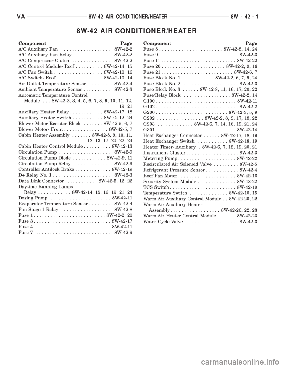
8W-42 AIR CONDITIONER/HEATER
Component Page
A/C Auxiliary Fan................... 8W-42-2
A/C Auxiliary Fan Relay............... 8W-42-2
A/C Compressor Clutch............... 8W-42-2
A/C Control Module- Roof.......... 8W-42-14, 15
A/C Fan Switch.................. 8W-42-10, 16
A/C Switch- Roof................. 8W-42-10, 14
Air Outlet Temperature Sensor......... 8W-42-4
Ambient Temperature Sensor........... 8W-42-3
Automatic Temperature Control
Module . . . 8W-42-2, 3, 4, 5, 6, 7, 8, 9, 10, 11, 12,
19, 21
Auxiliary Heater Relay............ 8W-42-17, 18
Auxiliary Heater Switch........... 8W-42-12, 24
Blower Motor Resistor Block....... 8W-42-5, 6, 7
Blower Motor- Front................ 8W-42-5, 7
Cabin Heater Assembly....... 8W-42-8, 9, 10, 11,
12, 13, 17, 20, 22, 24
Cabin Heater Control Module.......... 8W-42-13
Circulation Pump.................... 8W-42-9
Circulation Pump Diode............ 8W-42-9, 11
Circulation Pump Relay............... 8W-42-9
Controller Antilock Brake............. 8W-42-19
D+ Relay No. 1...................... 8W-42-3
Data Link Connector........... 8W-42-5, 12, 22
Daytime Running Lamps
Relay............ 8W-42-14, 15, 16, 19, 21, 24
Dosing Pump...................... 8W-42-11
Evaporator Temperature Sensor......... 8W-42-4
Fan Stage 1 Relay................... 8W-42-8
Fuse 1.......................... 8W-42-2, 20
Fuse 3............................ 8W-42-17
Fuse 4............................ 8W-42-11
Fuse 7............................ 8W-42-9Component Page
Fuse 8....................... 8W-42-8, 14, 24
Fuse 9............................ 8W-42-3
Fuse 11........................... 8W-42-22
Fuse 20....................... 8W-42-2, 9, 16
Fuse 21.......................... 8W-42-6, 7
Fuse Block No. 1............ 8W-42-2, 6, 7, 9, 24
Fuse Block No. 2.................... 8W-42-3
Fuse Block No. 3...... 8W-42-8, 11, 16, 17, 20, 22
Fuse/Relay Block................. 8W-42-2, 14
G100............................. 8W-42-11
G102.............................. 8W-42-2
G200.......................... 8W-42-3, 5, 9
G202................. 8W-42-2, 8, 9, 17, 18, 22
G203............. 8W-42-6, 7, 14, 16, 19, 21, 24
G301............................. 8W-42-14
Heat Exchanger Connector...... 8W-42-17, 18, 19
Heat Exchanger Switch........... 8W-42-18, 19
Heater Timer- Auxiliary . 8W-42-6, 7, 12, 19, 20, 21
Instrument Cluster................... 8W-42-3
Metering Pump..................... 8W-42-22
Recirculated Air Solenoid Valve......... 8W-42-5
Refrigerant Pressure Sensor............ 8W-42-4
Roof Fan Motor..................... 8W-42-16
Security System Module.............. 8W-42-22
TCS Switch........................ 8W-42-19
Temperature Switch.............. 8W-42-10, 15
Warm Air Auxiliary Control Module . . 8W-42-20, 22
Warm Air Auxiliary Heater
Assembly.................. 8W-42-20, 22, 23
Warm Air Heater Control Module....... 8W-42-23
Water Cycle Valve................... 8W-42-3
VA8W-42 AIR CONDITIONER/HEATER 8W - 42 - 1
Page 628 of 1232
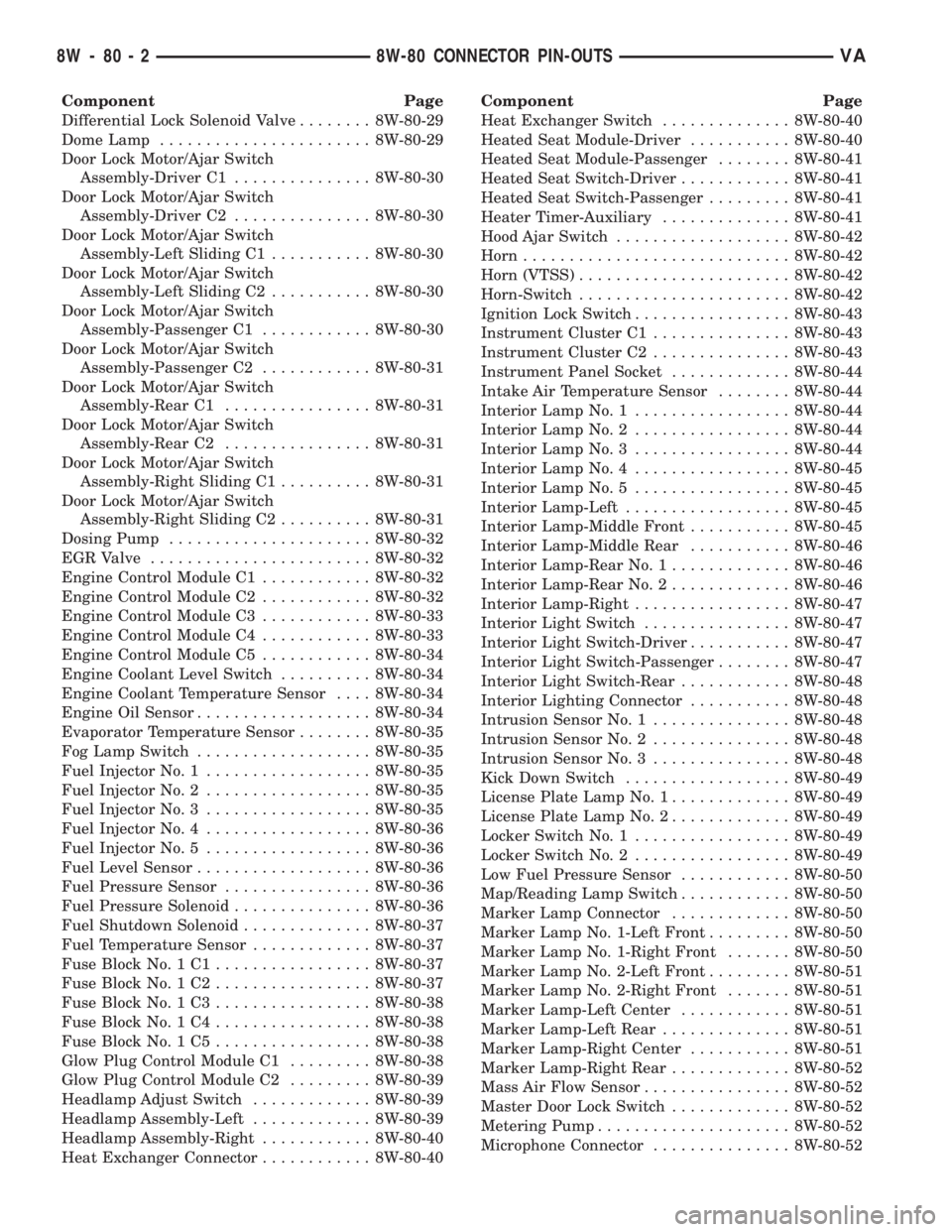
Component Page
Differential Lock Solenoid Valve........ 8W-80-29
Dome Lamp....................... 8W-80-29
Door Lock Motor/Ajar Switch
Assembly-Driver C1............... 8W-80-30
Door Lock Motor/Ajar Switch
Assembly-Driver C2............... 8W-80-30
Door Lock Motor/Ajar Switch
Assembly-Left Sliding C1........... 8W-80-30
Door Lock Motor/Ajar Switch
Assembly-Left Sliding C2........... 8W-80-30
Door Lock Motor/Ajar Switch
Assembly-Passenger C1............ 8W-80-30
Door Lock Motor/Ajar Switch
Assembly-Passenger C2............ 8W-80-31
Door Lock Motor/Ajar Switch
Assembly-Rear C1................ 8W-80-31
Door Lock Motor/Ajar Switch
Assembly-Rear C2................ 8W-80-31
Door Lock Motor/Ajar Switch
Assembly-Right Sliding C1.......... 8W-80-31
Door Lock Motor/Ajar Switch
Assembly-Right Sliding C2.......... 8W-80-31
Dosing Pump...................... 8W-80-32
EGR Valve........................ 8W-80-32
Engine Control Module C1............ 8W-80-32
Engine Control Module C2............ 8W-80-32
Engine Control Module C3............ 8W-80-33
Engine Control Module C4............ 8W-80-33
Engine Control Module C5............ 8W-80-34
Engine Coolant Level Switch.......... 8W-80-34
Engine Coolant Temperature Sensor.... 8W-80-34
Engine Oil Sensor................... 8W-80-34
Evaporator Temperature Sensor........ 8W-80-35
Fog Lamp Switch................... 8W-80-35
Fuel Injector No. 1.................. 8W-80-35
Fuel Injector No. 2.................. 8W-80-35
Fuel Injector No. 3.................. 8W-80-35
Fuel Injector No. 4.................. 8W-80-36
Fuel Injector No. 5.................. 8W-80-36
Fuel Level Sensor................... 8W-80-36
Fuel Pressure Sensor................ 8W-80-36
Fuel Pressure Solenoid............... 8W-80-36
Fuel Shutdown Solenoid.............. 8W-80-37
Fuel Temperature Sensor............. 8W-80-37
Fuse Block No. 1 C1................. 8W-80-37
Fuse Block No. 1 C2................. 8W-80-37
Fuse Block No. 1 C3................. 8W-80-38
Fuse Block No. 1 C4................. 8W-80-38
Fuse Block No. 1 C5................. 8W-80-38
Glow Plug Control Module C1......... 8W-80-38
Glow Plug Control Module C2......... 8W-80-39
Headlamp Adjust Switch............. 8W-80-39
Headlamp Assembly-Left............. 8W-80-39
Headlamp Assembly-Right............ 8W-80-40
Heat Exchanger Connector............ 8W-80-40Component Page
Heat Exchanger Switch.............. 8W-80-40
Heated Seat Module-Driver........... 8W-80-40
Heated Seat Module-Passenger........ 8W-80-41
Heated Seat Switch-Driver............ 8W-80-41
Heated Seat Switch-Passenger......... 8W-80-41
Heater Timer-Auxiliary.............. 8W-80-41
Hood Ajar Switch................... 8W-80-42
Horn............................. 8W-80-42
Horn (VTSS)....................... 8W-80-42
Horn-Switch....................... 8W-80-42
Ignition Lock Switch................. 8W-80-43
Instrument Cluster C1............... 8W-80-43
Instrument Cluster C2............... 8W-80-43
Instrument Panel Socket............. 8W-80-44
Intake Air Temperature Sensor........ 8W-80-44
Interior Lamp No. 1................. 8W-80-44
Interior Lamp No. 2................. 8W-80-44
Interior Lamp No. 3................. 8W-80-44
Interior Lamp No. 4................. 8W-80-45
Interior Lamp No. 5................. 8W-80-45
Interior Lamp-Left.................. 8W-80-45
Interior Lamp-Middle Front........... 8W-80-45
Interior Lamp-Middle Rear........... 8W-80-46
Interior Lamp-Rear No. 1............. 8W-80-46
Interior Lamp-Rear No. 2............. 8W-80-46
Interior Lamp-Right................. 8W-80-47
Interior Light Switch................ 8W-80-47
Interior Light Switch-Driver........... 8W-80-47
Interior Light Switch-Passenger........ 8W-80-47
Interior Light Switch-Rear............ 8W-80-48
Interior Lighting Connector........... 8W-80-48
Intrusion Sensor No. 1............... 8W-80-48
Intrusion Sensor No. 2............... 8W-80-48
Intrusion Sensor No. 3............... 8W-80-48
Kick Down Switch.................. 8W-80-49
License Plate Lamp No. 1............. 8W-80-49
License Plate Lamp No. 2............. 8W-80-49
Locker Switch No. 1................. 8W-80-49
Locker Switch No. 2................. 8W-80-49
Low Fuel Pressure Sensor............ 8W-80-50
Map/Reading Lamp Switch............ 8W-80-50
Marker Lamp Connector............. 8W-80-50
Marker Lamp No. 1-Left Front......... 8W-80-50
Marker Lamp No. 1-Right Front....... 8W-80-50
Marker Lamp No. 2-Left Front......... 8W-80-51
Marker Lamp No. 2-Right Front....... 8W-80-51
Marker Lamp-Left Center............ 8W-80-51
Marker Lamp-Left Rear.............. 8W-80-51
Marker Lamp-Right Center........... 8W-80-51
Marker Lamp-Right Rear............. 8W-80-52
Mass Air Flow Sensor................ 8W-80-52
Master Door Lock Switch............. 8W-80-52
Metering Pump..................... 8W-80-52
Microphone Connector............... 8W-80-52
8W - 80 - 2 8W-80 CONNECTOR PIN-OUTSVA
Page 666 of 1232
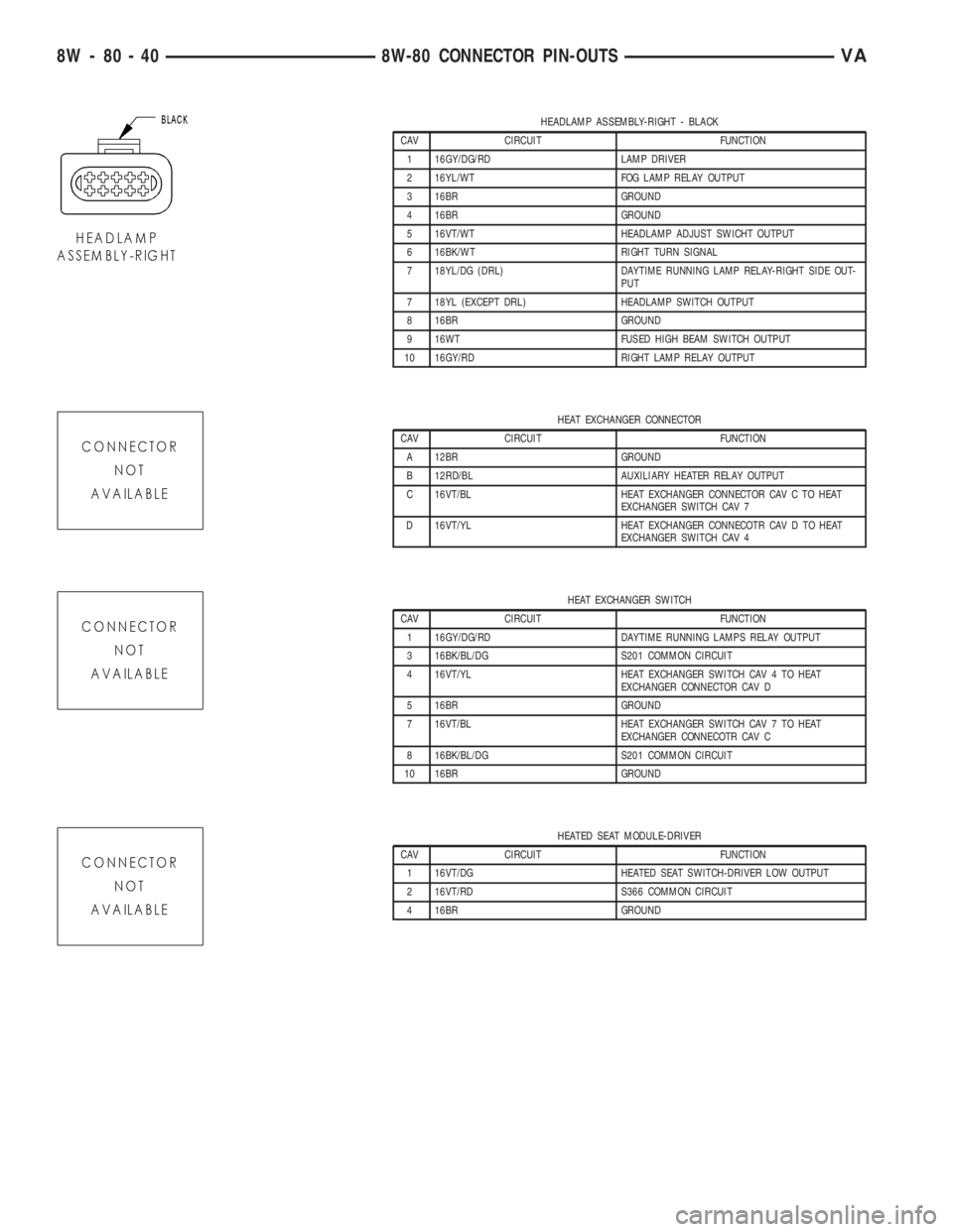
HEADLAMP ASSEMBLY-RIGHT - BLACK
CAV CIRCUIT FUNCTION
1 16GY/DG/RD LAMP DRIVER
2 16YL/WT FOG LAMP RELAY OUTPUT
3 16BR GROUND
4 16BR GROUND
5 16VT/WT HEADLAMP ADJUST SWICHT OUTPUT
6 16BK/WT RIGHT TURN SIGNAL
7 18YL/DG (DRL) DAYTIME RUNNING LAMP RELAY-RIGHT SIDE OUT-
PUT
7 18YL (EXCEPT DRL) HEADLAMP SWITCH OUTPUT
8 16BR GROUND
9 16WT FUSED HIGH BEAM SWITCH OUTPUT
10 16GY/RD RIGHT LAMP RELAY OUTPUT
HEAT EXCHANGER CONNECTOR
CAV CIRCUIT FUNCTION
A 12BR GROUND
B 12RD/BL AUXILIARY HEATER RELAY OUTPUT
C 16VT/BL HEAT EXCHANGER CONNECTOR CAV C TO HEAT
EXCHANGER SWITCH CAV 7
D 16VT/YL HEAT EXCHANGER CONNECOTR CAV D TO HEAT
EXCHANGER SWITCH CAV 4
HEAT EXCHANGER SWITCH
CAV CIRCUIT FUNCTION
1 16GY/DG/RD DAYTIME RUNNING LAMPS RELAY OUTPUT
3 16BK/BL/DG S201 COMMON CIRCUIT
4 16VT/YL HEAT EXCHANGER SWITCH CAV 4 TO HEAT
EXCHANGER CONNECTOR CAV D
5 16BR GROUND
7 16VT/BL HEAT EXCHANGER SWITCH CAV 7 TO HEAT
EXCHANGER CONNECOTR CAV C
8 16BK/BL/DG S201 COMMON CIRCUIT
10 16BR GROUND
HEATED SEAT MODULE-DRIVER
CAV CIRCUIT FUNCTION
1 16VT/DG HEATED SEAT SWITCH-DRIVER LOW OUTPUT
2 16VT/RD S366 COMMON CIRCUIT
4 16BR GROUND
8W - 80 - 40 8W-80 CONNECTOR PIN-OUTSVA
Page 794 of 1232
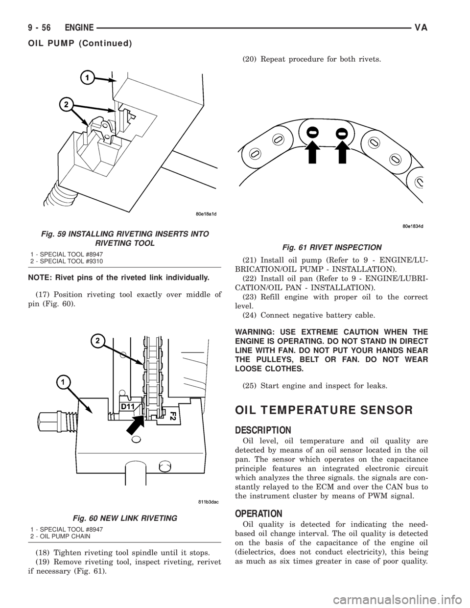
NOTE: Rivet pins of the riveted link individually.
(17) Position riveting tool exactly over middle of
pin (Fig. 60).
(18) Tighten riveting tool spindle until it stops.
(19) Remove riveting tool, inspect riveting, rerivet
if necessary (Fig. 61).(20) Repeat procedure for both rivets.
(21) Install oil pump (Refer to 9 - ENGINE/LU-
BRICATION/OIL PUMP - INSTALLATION).
(22) Install oil pan (Refer to 9 - ENGINE/LUBRI-
CATION/OIL PAN - INSTALLATION).
(23) Refill engine with proper oil to the correct
level.
(24) Connect negative battery cable.
WARNING: USE EXTREME CAUTION WHEN THE
ENGINE IS OPERATING. DO NOT STAND IN DIRECT
LINE WITH FAN. DO NOT PUT YOUR HANDS NEAR
THE PULLEYS, BELT OR FAN. DO NOT WEAR
LOOSE CLOTHES.
(25) Start engine and inspect for leaks.
OIL TEMPERATURE SENSOR
DESCRIPTION
Oil level, oil temperature and oil quality are
detected by means of an oil sensor located in the oil
pan. The sensor which operates on the capacitance
principle features an integrated electronic circuit
which analyzes the three signals. the signals are con-
stantly relayed to the ECM and over the CAN bus to
the instrument cluster by means of PWM signal.
OPERATION
Oil quality is detected for indicating the need-
based oil change interval. The oil quality is detected
on the basis of the capacitance of the engine oil
(dielectrics, does not conduct electricity), this being
as much as six times greater in case of poor quality.
Fig. 59 INSTALLING RIVETING INSERTS INTO
RIVETING TOOL
1 - SPECIAL TOOL #8947
2 - SPECIAL TOOL #9310
Fig. 60 NEW LINK RIVETING
1 - SPECIAL TOOL #8947
2 - OIL PUMP CHAIN
Fig. 61 RIVET INSPECTION
9 - 56 ENGINEVA
OIL PUMP (Continued)
Page 798 of 1232
(6) Remove the oil filter to allow the oil to flow off
into the oil pan.
(7) Remove the radiator assembly (Refer to 7 -
COOLING/ENGINE/RADIATOR - REMOVAL).
(8) Remove engine cover (Refer to 9 - ENGINE -
REMOVAL).
(9) Remove front cover at cylinder head (Refer to 9
- ENGINE/CYLINDER HEAD - REMOVAL).
(10) Remove accessory drive belt.
(11) Remove the high pressure fuel pump (Refer to
14 - FUEL SYSTEM/FUEL DELIVERY/FUEL PUMP
- REMOVAL).
(12) Remove water pump (Refer to 7 - COOLING/
ENGINE/WATER PUMP - REMOVAL).
(13) Remove accessory drive belt pulley and vibra-
tion damper (Refer to 9 - ENGINE/ENGINE BLOCK/
VIBRATION DAMPER - REMOVAL).
(14) Remove the power steering pump.
NOTE: NO NOT open the air conditioning system.
(15) Unplug AC compressor electrical connector
and unbolt AC compressor. Relocate in lower engine
compartmentwith outopening the system.
(16) Remove the generator with wiring attached
and relocate somewhere in the engine compartment.
(17) Install engine support fixture.
(18) Remove the oil pan.
(19) Detach the coolant hose to oil-water heat
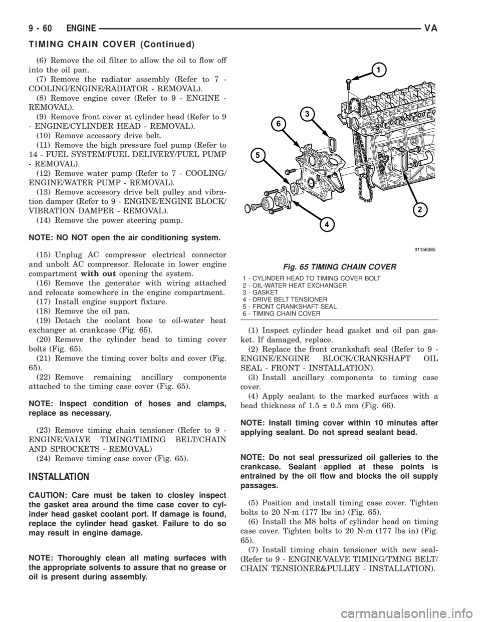
exchanger at crankcase (Fig. 65).
(20) Remove the cylinder head to timing cover
bolts (Fig. 65).
(21) Remove the timing cover bolts and cover (Fig.
65).
(22) Remove remaining ancillary components
attached to the timing case cover (Fig. 65).
NOTE: Inspect condition of hoses and clamps,
replace as necessary.
(23) Remove timing chain tensioner (Refer to 9 -
ENGINE/VALVE TIMING/TIMING BELT/CHAIN
AND SPROCKETS - REMOVAL)
(24) Remove timing case cover (Fig. 65).
INSTALLATION
CAUTION: Care must be taken to closley inspect
the gasket area around the time case cover to cyl-
inder head gasket coolant port. If damage is found,
replace the cylinder head gasket. Failure to do so
may result in engine damage.
NOTE: Thoroughly clean all mating surfaces with
the appropriate solvents to assure that no grease or
oil is present during assembly.(1) Inspect cylinder head gasket and oil pan gas-
ket. If damaged, replace.
(2) Replace the front crankshaft seal (Refer to 9 -
ENGINE/ENGINE BLOCK/CRANKSHAFT OIL
SEAL - FRONT - INSTALLATION).
(3) Install ancillary components to timing case
cover.
(4) Apply sealant to the marked surfaces with a
bead thickness of 1.5 0.5 mm (Fig. 66).
NOTE: Install timing cover within 10 minutes after
applying sealant. Do not spread sealant bead.
NOTE: Do not seal pressurized oil galleries to the
crankcase. Sealant applied at these points is
entrained by the oil flow and blocks the oil supply
passages.
(5) Position and install timing case cover. Tighten
bolts to 20 N´m (177 lbs in) (Fig. 65).
(6) Install the M8 bolts of cylinder head on timing
case cover. Tighten bolts to 20 N´m (177 lbs in) (Fig.
65).
(7) Install timing chain tensioner with new seal-
(Refer to 9 - ENGINE/VALVE TIMING/TMNG BELT/
CHAIN TENSIONER&PULLEY - INSTALLATION).
Fig. 65 TIMING CHAIN COVER
1 - CYLINDER HEAD TO TIMING COVER BOLT
2 - OIL-WATER HEAT EXCHANGER
3 - GASKET
4 - DRIVE BELT TENSIONER
5 - FRONT CRANKSHAFT SEAL
6 - TIMING CHAIN COVER
9 - 60 ENGINEVA
TIMING CHAIN COVER (Continued)
Page 979 of 1232
(4) Actuate the service brake. Start engine and let
it run at idle speed in selector lever position9P9.
(5) Shift through the transmission modes several
times with the vehicle stationary and the engine
idling
(6) Warm up the transmission, wait at least 2 min-
utes and check the oil level with the engine running.
Push the Oil Dipstick 8863A in up to the stop on the
electrohydraulic unit and pull out again, read off oil
level, repeat if necessary.
NOTE: The dipstick will protrude from the fill tube
approximately 75mm (3 inches) when installed.
(7) Check transmission oil temperature.
NOTE: The true transmission oil temperature can
only be read by a scan tool in REVERSE or any for-
ward gear position. (Refer to 21 - AUTOMATIC
TRANSMISSION- NAG1/TRANSMISSION TEMPERA-
TURE SENSOR/PARK-NEUTRAL SWITCH - OPERA-
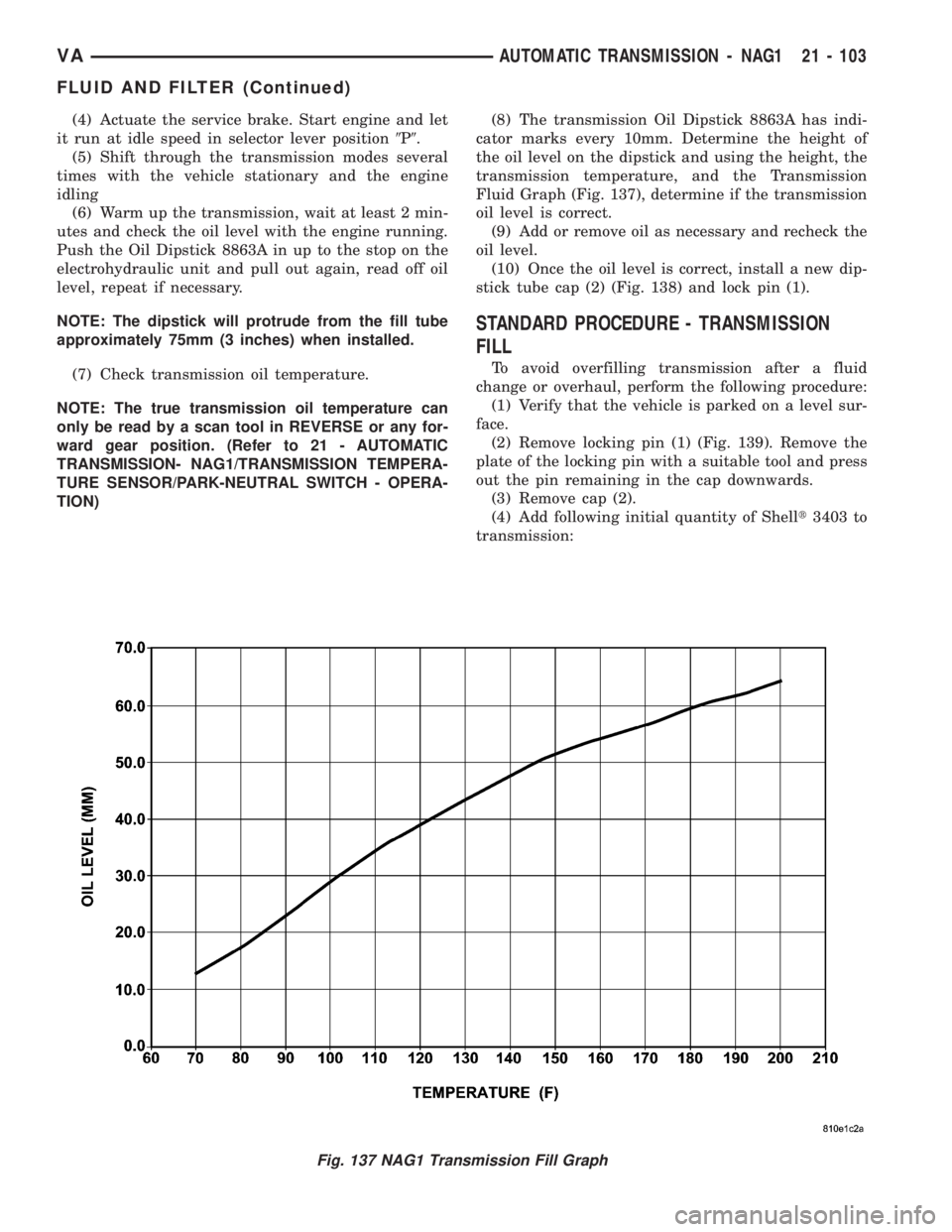
TION)(8) The transmission Oil Dipstick 8863A has indi-
cator marks every 10mm. Determine the height of
the oil level on the dipstick and using the height, the
transmission temperature, and the Transmission
Fluid Graph (Fig. 137), determine if the transmission
oil level is correct.
(9) Add or remove oil as necessary and recheck the
oil level.
(10) Once the oil level is correct, install a new dip-
stick tube cap (2) (Fig. 138) and lock pin (1).
STANDARD PROCEDURE - TRANSMISSION
FILL
To avoid overfilling transmission after a fluid
change or overhaul, perform the following procedure:
(1) Verify that the vehicle is parked on a level sur-
face.
(2) Remove locking pin (1) (Fig. 139). Remove the
plate of the locking pin with a suitable tool and press
out the pin remaining in the cap downwards.
(3) Remove cap (2).
(4) Add following initial quantity of Shellt3403 to
transmission:
Fig. 137 NAG1 Transmission Fill Graph
VAAUTOMATIC TRANSMISSION - NAG1 21 - 103
FLUID AND FILTER (Continued)
Page 1010 of 1232
Tipping the shift lever will have the following
results:
²Tipping the selector lever toward(-(one
time after another:The shift range is reduced in
descending sequence by one gear each time, i.e., from
D-4-3-2-1.Iftheselected limitation of the shift
range would result in a downshift causing excessive
engine speed, the shifting is not executed and the
engaged gear as well as the shift range remain
unchanged. This is to prevent the engine from over-
speeding. Engine retardation is low with the selector
lever in position9D9. To make use of the full braking
power of the engine,9manual9downshifting by tip-
ping the lever towards the left-hand side is recom-
mended. If this has been done, subsequent upshifting
must be carried out manually as well.
²Tipping the selector lever toward(-(and
holding it in this position:The currently engaged
gear in range9D9is indicated in the instrument clus-
ter display and the shift range is limited to this gear.
²Tipping the selector lever toward(+(one
time after another:The shift range is increased by
one gear each time and the increased shift range is
displayed in the instrument cluster; possibly, the
transmission upshifts to a faster gear.
²Tipping the selector lever toward(+(sev-
eral times:The shift range is increased by one gear
each time the lever is tipped until the shift range
ends up in9D9.
²Tipping the selector lever toward(+(and
holding it in this position:The shift range is
extended immediately to9D9, shift ranges are indi-
cated in ascending sequence; possibly, the transmis-
sion upshifts to a faster gear due to the extension of
the shift range.
REMOVAL
(1) Move selector lever to position9D9.
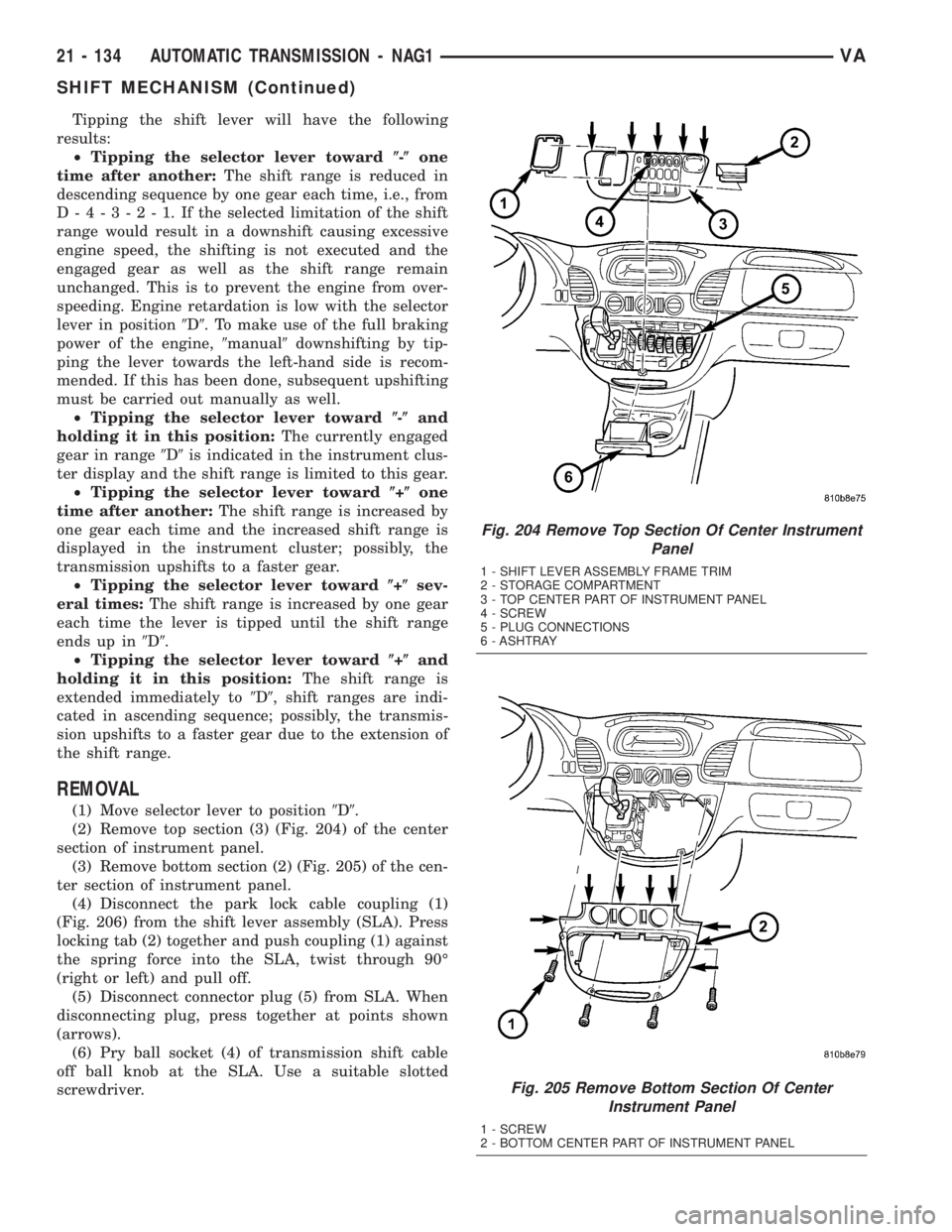
(2) Remove top section (3) (Fig. 204) of the center
section of instrument panel.
(3) Remove bottom section (2) (Fig. 205) of the cen-
ter section of instrument panel.
(4) Disconnect the park lock cable coupling (1)
(Fig. 206) from the shift lever assembly (SLA). Press
locking tab (2) together and push coupling (1) against
the spring force into the SLA, twist through 90É
(right or left) and pull off.
(5) Disconnect connector plug (5) from SLA. When
disconnecting plug, press together at points shown
(arrows).
(6) Pry ball socket (4) of transmission shift cable
off ball knob at the SLA. Use a suitable slotted
screwdriver.
Fig. 204 Remove Top Section Of Center Instrument
Panel
1 - SHIFT LEVER ASSEMBLY FRAME TRIM
2 - STORAGE COMPARTMENT
3 - TOP CENTER PART OF INSTRUMENT PANEL
4 - SCREW
5 - PLUG CONNECTIONS
6 - ASHTRAY
Fig. 205 Remove Bottom Section Of Center
Instrument Panel
1 - SCREW
2 - BOTTOM CENTER PART OF INSTRUMENT PANEL
21 - 134 AUTOMATIC TRANSMISSION - NAG1VA
SHIFT MECHANISM (Continued)