2005 MERCEDES-BENZ SPRINTER traction control
[x] Cancel search: traction controlPage 125 of 1232
TRANSMISSION CONTROL
MODULE
DESCRIPTION
The transmission control module (TCM) receives,
processes and sends various digital and analog sig-
nals related to the automatic transmission. In addi-
tion, it processes information received from other
vehicle systems, such as engine torque and speed,
accelerator pedal position, wheel speed, kick-down
switch, traction control information, etc.
The TCM is located under the driver's seat and is
connected to other control modules via a CAN bus. It
controls all shift functions to achieve smooth shift
comfort in all driving situations considering:
²Vehicle speed.
²Transmission status.
²Position of selector lever.
²Selected shift range.
²CAN signals.
²Engine Status.Engine speed limits may be reached in all gears
with full throttle or in kick-down operation. In for-
ward driving, the shift range of the forward gears
can be adjusted by the operator by tipping the selec-
tor lever to the left or right (AutoStick). However, the
TCM features a downshift inhibitor to prevent the
engine from overspeeding.
OPERATION
The transmission control module (TCM) deter-
mines the current operating conditions of the vehicle
and controls the shifting process for shift comfort and
driving situations. It receives this operating data
from sensors and broadcast messages from other
modules.
The TCM uses inputs from several sensors that are
directly hardwired to the controller and it uses sev-
eral indirect inputs that are used to control shifts.
This information is used to actuate the proper sole-
noids in the valve body to achieve the desired gear.
The shift lever assembly (SLA) has several items
that are monitored by the TCM to calculate shift
lever position. The reverse light switch, an integral
part of the SLA, controls the reverse light relay con-
trol circuit. The Brake/Transmission Shift Interlock
(BTSI) solenoid and the park lockout solenoid (also
part of the SLA) are controlled by the TCM.
The ECM and ABS broadcast messages over the
controller area network (CAN C) bus for use by the
TCM. The TCM uses this information, with other
inputs, to determine the transmission operating con-
ditions.
The TCM:
²determines the momentary operating conditions
of the vehicle.
²controls all shift processes.
²considers shift comfort and the driving situation.
The TCM controls the solenoid valves for modulat-
ing shift pressures and gear changes. Relative to the
torque being transmitted, the required pressures are
calculated from load conditions, engine rpm, vehicle
speed, and ATF temperature.
The following functions are contained in the TCM:
²Shift Program
²Downshift Safety
²Torque Converter Lock-Up Clutch.
²Adaptation.
This transmission does not have a TCM relay.
Power is supplied to the SLA and the TCM directly
from the ignition.
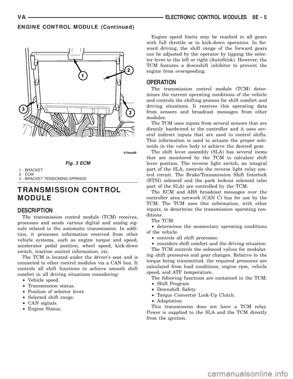
Fig. 3 ECM
1 - BRACKET
2 - ECM
3 - BRACKET TENSIONING SPRINGS
VAELECTRONIC CONTROL MODULES 8E - 5
ENGINE CONTROL MODULE (Continued)
Page 171 of 1232
INSTRUMENT CLUSTER
TABLE OF CONTENTS
page page
INSTRUMENT CLUSTER
DESCRIPTION..........................2
OPERATION............................5
DIAGNOSIS AND TESTING - INSTRUMENT
CLUSTER............................7
REMOVAL.............................7
INSTALLATION..........................9
ABS INDICATOR
DESCRIPTION..........................9
OPERATION............................9
AIRBAG INDICATOR
DESCRIPTION.........................10
OPERATION...........................10
AMBIENT TEMPERATURE INDICATOR
DESCRIPTION.........................11
OPERATION...........................11
BRAKE/PARK BRAKE INDICATOR
DESCRIPTION.........................11
OPERATION...........................12
BRAKE WEAR INDICATOR
DESCRIPTION.........................12
OPERATION...........................12
CHARGING INDICATOR
DESCRIPTION.........................13
OPERATION...........................13
CLOCK
DESCRIPTION.........................13
OPERATION...........................14
COOLANT LOW INDICATOR
DESCRIPTION.........................14
OPERATION...........................14
ENGINE TEMPERATURE GAUGE
DESCRIPTION.........................15
OPERATION...........................15
FUEL FILTER CLOGGED INDICATOR
DESCRIPTION.........................15
OPERATION...........................15
FUEL GAUGE
DESCRIPTION.........................16
OPERATION...........................16
GEAR SELECTOR INDICATOR
DESCRIPTION.........................17
OPERATION...........................17
HIGH BEAM INDICATOR
DESCRIPTION.........................17
OPERATION...........................17LOW FUEL INDICATOR
DESCRIPTION.........................18
OPERATION...........................18
LOW OIL LEVEL INDICATOR
DESCRIPTION.........................18
OPERATION...........................18
MAINTENANCE INDICATOR
DESCRIPTION.........................19
OPERATION...........................19
MALFUNCTION INDICATOR LAMP (MIL)
DESCRIPTION.........................20
OPERATION...........................20
MULTI-FUNCTION INDICATOR
DESCRIPTION.........................20
OPERATION...........................21
ODOMETER
DESCRIPTION.........................21
OPERATION...........................22
SEATBELT INDICATOR
DESCRIPTION.........................22
OPERATION...........................22
SPEEDOMETER
DESCRIPTION.........................23
OPERATION...........................23
TACHOMETER
DESCRIPTION.........................23
OPERATION...........................24
TRACTION CONTROL INDICATOR
DESCRIPTION.........................24
OPERATION...........................24
TRACTION CONTROL MALFUNCTION
INDICATOR
DESCRIPTION.........................25
OPERATION...........................25
TURN SIGNAL INDICATOR
DESCRIPTION.........................25
OPERATION...........................25
WAIT-TO-START INDICATOR
DESCRIPTION.........................26
OPERATION...........................26
WASHER FLUID INDICATOR
DESCRIPTION.........................27
OPERATION...........................27
WATER-IN-FUEL INDICATOR
DESCRIPTION.........................27
OPERATION...........................28
VAINSTRUMENT CLUSTER 8J - 1
Page 173 of 1232
arate take out and connector of the vehicle wire
harness.
Located between the rear cover and the cluster
hood is the cluster housing. The molded plastic clus-
ter housing serves as the carrier for the cluster elec-
tronic circuit board and circuitry, the cluster
connector receptacles, the gauges, a Light Emitting
Diode (LED) for each cluster indicator and general
illumination lamp, the multi-function indicator LCD
unit, electronic tone generators, the cluster overlay,
the gauge pointers, the multi-function indicator
switches and the four switch push buttons.
The cluster overlay is a laminated plastic unit. The
dark, visible, outer surface of the overlay is marked
with all of the gauge dial faces and graduations, but
this layer is also translucent. The darkness of this
outer layer prevents the cluster from appearing clut-
tered or busy by concealing the cluster indicators
that are not illuminated, while the translucence of
this layer allows those indicators and icons that are
illuminated to be readily visible. The underlying
layer of the overlay is opaque and allows light from
the LED for each of the various indicators and illu-
mination lamps behind it to be visible through the
outer layer of the overlay only through predeter-
mined cutouts. A rectangular opening in the overlay
at the base of the speedometer provides a window
through which the illuminated multi-function indica-
tor LCD unit can be viewed.
Several versions of the EMIC module are offered
on this model. These versions accommodate all of the
variations of optional equipment and regulatory
requirements for the various markets in which the
vehicle will be offered. The microprocessor-based
EMIC utilizes integrated circuitry, Electrically Eras-
able Programmable Read Only Memory (EEPROM)
type memory storage, information carried on the
Controller Area Network (CAN) data bus, along with
several hard wired analog and multiplexed inputs to
monitor systems, sensors and switches throughout
the vehicle.
In response to those inputs, the hardware and soft-
ware of the EMIC allow it to control and integrate
many electronic functions and features of the vehicle
through both hard wired outputs and the transmis-
sion of electronic message outputs to other electronic
modules in the vehicle over the CAN data bus. (Refer
to 8 - ELECTRICAL/ELECTRONIC CONTROL
MODULES/COMMUNICATION - DESCRIPTION -
CAN BUS).
Besides typical instrument cluster gauge and indi-
cator support, the electronic functions and features
that the EMIC supports or controls include the fol-
lowing:
²Active Service System- In vehicles equipped
with the Active Service SYSTem (ASSYST) engine oilmaintenance indicator option, the EMIC electronic
circuit board includes a second dedicated micropro-
cessor. This second microprocessor evaluates various
data including time, mileage, and driving conditions
to calculate the required engine oil service intervals,
and provides both visual and audible alerts to the
vehicle operator when certain engine oil maintenance
services are required.
²Audible Warnings- The EMIC electronic cir-
cuit board is equipped with an audible tone generator
and programming that allows it to provide various
audible alerts to the vehicle operator, including buzz-
ing and chime tones. An audible contactless elec-
tronic relay is also soldered onto the circuit board to
produce audible clicks that is synchronized with turn
signal indicator flashing to emulate the sounds of a
conventional turn signal or hazard warning flasher.
These audible clicks can occur at one of two rates to
emulate both normal and bulb-out turn or hazard
flasher operation. (Refer to 8 - ELECTRICAL/
CHIME/BUZZER - DESCRIPTION).
²Panel Lamps Dimming Control- The EMIC
provides a hard wired 12-volt Pulse-Width Modulated
(PWM) output that synchronizes the dimming level
of all panel lamps dimmer controlled lamps with that
of the cluster general illumination lamps and multi-
function indicator.
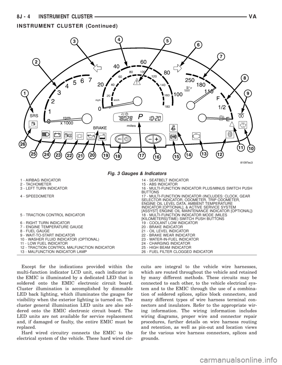
The EMIC houses four analog gauges and has pro-
visions for up to nineteen indicators (Fig. 3). The
EMIC includes the following analog gauges:
²Coolant Temperature Gauge
²Fuel Gauge
²Speedometer
²Tachometer
The EMIC includes provisions for the following
indicators (Fig. 3):
²Airbag (SRS) Indicator
²Antilock Brake System (ABS) Indicator
²Brake Indicator
²Brake Wear Indicator
²Charging Indicator
²Clogged Fuel Filter Indicator
²Coolant Low Indicator
²High Beam Indicator
²Low Fuel Indicator
²Malfunction Indicator Lamp (MIL)
²Multi-Function Indicator (LCD)
²Seatbelt Indicator
²Traction Control (ASR) Indicator
²Traction Control (ASR) Malfunction Indica-
tor
²Turn Signal (Right and Left) Indicators
²Washer Fluid Indicator
²Wait-To-Start Indicator
²Water-In-Fuel Indicator
VAINSTRUMENT CLUSTER 8J - 3
INSTRUMENT CLUSTER (Continued)
Page 174 of 1232
Except for the indications provided within the
multi-function indicator LCD unit, each indicator in
the EMIC is illuminated by a dedicated LED that is
soldered onto the EMIC electronic circuit board.
Cluster illumination is accomplished by dimmable
LED back lighting, which illuminates the gauges for
visibility when the exterior lighting is turned on. The
cluster general illumination LED units are also sol-
dered onto the EMIC electronic circuit board. The
LED units are not available for service replacement
and, if damaged or faulty, the entire EMIC must be
replaced.
Hard wired circuitry connects the EMIC to the
electrical system of the vehicle. These hard wired cir-cuits are integral to the vehicle wire harnesses,
which are routed throughout the vehicle and retained
by many different methods. These circuits may be
connected to each other, to the vehicle electrical sys-
tem and to the EMIC through the use of a combina-
tion of soldered splices, splice block connectors, and
many different types of wire harness terminal con-
nectors and insulators. Refer to the appropriate wir-
ing information. The wiring information includes
wiring diagrams, proper wire and connector repair
procedures, further details on wire harness routing
and retention, as well as pin-out and location views
for the various wire harness connectors, splices and
grounds.
Fig. 3 Gauges & Indicators
1 - AIRBAG INDICATOR 14 - SEATBELT INDICATOR
2 - TACHOMETER 15 - ABS INDICATOR
3 - LEFT TURN INDICATOR 16 - MULTI-FUNCTION INDICATOR PLUS/MINUS SWITCH PUSH
BUTTONS
4 - SPEEDOMETER 17 - MULTI-FUNCTION INDICATOR (INCLUDES: CLOCK, GEAR
SELECTOR INDICATOR, ODOMETER, TRIP ODOMETER,
ENGINE OIL LEVEL DATA, AMBIENT TEMPERATURE
INDICATOR [OPTIONAL], & ACTIVE SERVICE SYSTEM
[ASSYST] ENGINE OIL MAINTENANCE INDICATOR [OPTIONAL])
5 - TRACTION CONTROL INDICATOR 18 - MULTI-FUNCTION INDICATOR MODE (MILES
[KILOMETERS]/TIME) SWITCH PUSH BUTTONS
6 - RIGHT TURN INDICATOR 19 - COOLANT LOW INDICATOR
7 - ENGINE TEMPERATURE GAUGE 20 - BRAKE INDICATOR
8 - FUEL GAUGE 21 - OIL LEVEL INDICATOR
9 - WAIT-TO-START INDICATOR 22 - BRAKE WEAR INDICATOR
10 - WASHER FLUID INDICATOR (OPTIONAL) 23 - WATER-IN-FUEL INDICATOR
11 - LOW FUEL INDICATOR 24 - CHARGING INDICATOR
12 - TRACTION CONTROL MALFUNCTION INDICATOR 25 - HIGH BEAM INDICATOR
13 - MALFUNCTION INDICATOR LAMP 26 - FUEL FILTER CLOGGED INDICATOR
8J - 4 INSTRUMENT CLUSTERVA
INSTRUMENT CLUSTER (Continued)
Page 194 of 1232
OPERATION
The tachometer gives an indication to the vehicle oper-
ator of the engine speed. This gauge is controlled by the
instrument cluster circuit board based upon cluster pro-
gramming and electronic messages received by the clus-
ter from the Engine Control Module (ECM) over the
Controller Area Network (CAN) data bus. The tachome-
ter is an air core magnetic unit that receives battery cur-
rent on the instrument cluster electronic circuit board
when the instrument cluster detects that the ignition
switch is in the On position. The cluster is programmed
to move the gauge needle back to the low end of the
scale after the ignition switch is turned to the Off posi-
tion. The instrument cluster circuitry controls the gauge
needle position and provides the following features:
²Engine Speed Message- Each time the cluster
receives an engine speed message from the ECM it
will calculate the correct engine speed reading and
position the gauge needle at that relative speed posi-
tion on the gauge scale. The gauge needle will con-
tinually be repositioned at the relative engine speed
position on the gauge scale until the engine stops
running, or until the ignition switch is turned to the
Off position, whichever occurs first.
²Communication Error- If the cluster fails to
receive an engine speed message, it will hold the
gauge needle at the last indication for about three
seconds, or until the ignition switch is turned to the
Off position, whichever occurs first. After three sec-
onds, the gauge needle will return to the left end of
the gauge scale.
The ECM continually monitors the crankshaft position
sensor to determine the engine speed. The ECM then
sends the proper engine speed messages to the instru-
ment cluster. For proper diagnosis of the crankshaft posi-
tion sensor, the ECM, the CAN data bus, or the
electronic message inputs to the instrument cluster that
control the tachometer, a DRBIIItscan tool is required.
Refer to the appropriate diagnostic information.
TRACTION CONTROL
INDICATOR
DESCRIPTION
A traction control (ASR) indicator is standard equip-
ment on all instrument clusters. The traction control
indicator is located near the center of the speedometer
in the instrument cluster. The traction control indicator
consists of an ª!º (exclamation point) imprinted within a
triangular cutout in the opaque layer of the instrument
cluster overlay. The dark outer layer of the overlay pre-
vents the indicator from being clearly visible when it is
not illuminated. An amber Light Emitting Diode (LED)
behind the cutout in the opaque layer of the overlay
causes the exclamation point to appear silhouettedagainst an amber field through the translucent outer
layer of the overlay when the indicator is illuminated
from behind by the LED, which is soldered onto the
instrument cluster electronic circuit board. The traction
control indicator is serviced as a unit with the instru-
ment cluster.
OPERATION
The traction control (ASR) indicator gives several
indications to the vehicle operator concerning the
operating status of the traction control (ASR) system.
The traction control indicator is controlled by a tran-
sistor on the instrument cluster circuit board based
upon cluster programming and electronic messages
received by the cluster from the Controller Anti-lock
Brake (CAB) over the Controller Area Network
(CAN) data bus. The traction control indicator Light
Emitting Diode (LED) is completely controlled by the
instrument cluster logic circuit, and that logic will
only allow this indicator to operate when the instru-
ment cluster detects that the ignition switch is in the
On position. Therefore, the LED will always be off
when the ignition switch is in any position except
On. The LED only illuminates when it is provided a
path to ground by the instrument cluster transistor.
The instrument cluster will turn on the traction con-
trol indicator for the following reasons:
²Bulb Test-
Each time the ignition switch is
turned to the On position the traction control indicator
is illuminated for about two seconds as a bulb test.
²Traction Control (ASR) Indicator Lamp-On
Message-
Each time the cluster receives a traction
control indicator lamp-on message from the CAB, the
indicator will be illuminated. This indicator can be
flashed on and off, or illuminated solid, as dictated by
the CAB message. The indicator is illuminated solid
when the traction control system has been deactivated;
and is flashed when the traction control is activated or
when the driven wheels lose traction with the traction
control deactivated. The indicator remains flashing or
illuminated solid until the cluster receives a lamp-off
message from the CAB, or until the ignition switch is
turned to the Off position, whichever occurs first.
The CAB continually monitors the traction control
(ASR) switch and the four wheel speed sensors to deter-
mine the correct operating mode for the traction control
system. The CAB then sends the proper lamp-on or lamp-
off messages to the instrument cluster. See the owner's
manual in the vehicle glove box for more information on
the features, use, activation and deactivation of the trac-
tion control (ASR) system. For proper diagnosis of the
traction control system, the CAB, the CAN data bus, or
the electronic message inputs to the instrument cluster
that control the traction control indicator, a DRBIIIt
scan tool is required. Refer to the appropriate diagnostic
information.
8J - 24 INSTRUMENT CLUSTERVA
TACHOMETER (Continued)
Page 195 of 1232
TRACTION CONTROL
MALFUNCTION INDICATOR
DESCRIPTION
A traction control (ASR) malfunction indicator is
standard equipment on all instrument clusters. The
traction control malfunction indicator is located near
the lower edge of the instrument cluster, to the right
of the multi-function indicator display. The traction
control malfunction indicator consists of an icon that
graphically depicts a tire and two skid marks
imprinted within a rectangular cutout in the opaque
layer of the instrument cluster overlay. The dark
outer layer of the overlay prevents the indicator from
being clearly visible when it is not illuminated. An
amber Light Emitting Diode (LED) behind the cutout
in the opaque layer of the overlay causes the icon to
appear silhouetted against an amber field through
the translucent outer layer of the overlay when the
indicator is illuminated from behind by the LED,
which is soldered onto the instrument cluster elec-
tronic circuit board. The traction control malfunction
indicator is serviced as a unit with the instrument
cluster.
OPERATION
The traction control (ASR) malfunction indicator
gives the vehicle operator an indication when the
traction control system is faulty or inoperative. This
indicator is controlled by a transistor on the instru-
ment cluster circuit board based upon cluster pro-
gramming and electronic messages received by the
cluster from the Controller Antilock Brake (CAB)
over the Controller Area Network (CAN) data bus.
The traction control malfunction indicator Light
Emitting Diode (LED) is completely controlled by the
instrument cluster logic circuit, and that logic will
only allow this indicator to operate when the instru-
ment cluster detects that the ignition switch is in the
On position. Therefore, the LED will always be off
when the ignition switch is in any position except
On. The LED only illuminates when it is provided a
path to ground by the instrument cluster transistor.
The instrument cluster will turn on the traction con-
trol malfunction indicator for the following reasons:
²Bulb Test- Each time the ignition switch is
turned to the On position the traction control indica-
tor is illuminated as a bulb test until the engine is
started.
²Traction Control (ASR) Malfunction Indica-
tor Lamp-On Message- Each time the cluster
receives a traction control malfunction indicator
lamp-on message from the CAB, the indicator will be
illuminated. The indicator remains illuminated until
the cluster receives a lamp-off message from theCAB, or until the ignition switch is turned to the Off
position, whichever occurs first.
The CAB continually monitors the traction control
(ASR) system circuits and sensors to decide whether
the system is in good operating condition. The CAB
then sends the proper lamp-on or lamp-off messages
to the instrument cluster. If the CAB sends a
lamp-on message after the bulb test, it indicates that
the CAB has detected a system malfunction and that
the traction control (ASR) system has become inoper-
ative. The CAB will store a Diagnostic Trouble Code
(DTC) for any malfunction it detects. In addition, if
the traction control malfunction indicator is illumi-
nated, the CAB will deactivate an activated traction
control system and engine power output may be
reduced. See the owner's manual in the vehicle glove
box for more information on the features, use, activa-
tion and deactivation of the traction control (ASR)
system. For proper diagnosis of the traction control
system, the CAB, the CAN data bus, or the electronic
message inputs to the instrument cluster that control
the traction control malfunction indicator, a DRBIIIt
scan tool is required. Refer to the appropriate diag-
nostic information.
TURN SIGNAL INDICATOR
DESCRIPTION
Two turn signal indicators, one right and one left,
are standard equipment on all instrument clusters.
The turn signal indicators are located near the upper
edge of the instrument cluster, one to each side of the
speedometer. Each turn signal indicator consists of a
arrow-shaped cutout of the International Control and
Display Symbol icon for ªTurn Warningº in the
opaque layer of the instrument cluster overlay. The
dark outer layer of the overlay prevents these icons
from being clearly visible when they are not illumi-
nated. A green Light Emitting Diode (LED) behind
each turn signal indicator cutout in the opaque layer
of the overlay causes the icon to appear in green
through the translucent outer layer of the overlay
when the indicator is illuminated from behind by the
LED, which is soldered onto the instrument cluster
electronic circuit board. The turn signal indicators
are serviced as a unit with the instrument cluster.
OPERATION
The turn signal indicators give an indication to the
vehicle operator that the turn signal (left or right
indicator flashing) or hazard warning (both left and
right indicators flashing) have been selected and are
operating. These indicators are controlled by transis-
tors on the instrument cluster electronic circuit board
based upon the cluster programming and a hard
VAINSTRUMENT CLUSTER 8J - 25
Page 752 of 1232
DESCRIPTION N´m Ft. Lbs. In. Lbs.
Threaded Rail to Rail 22 16 -
Fuel Cooling System
Bolt-Fuel Cooler to
Charge Air Distribution
Pipe14 - 124
Heater Booster, Heater Unit
Bolt- Temperature
Controlled Cut Out to
Heater Booster Control
Module12 - 106
Nut-Threaded Stud to
Electronic Heater Booster18 - 159
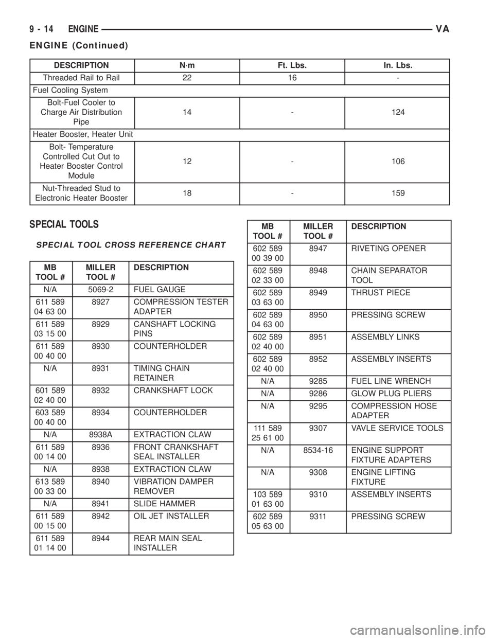
SPECIAL TOOLS
SPECIAL TOOL CROSS REFERENCE CHART
MB
TOOL #MILLER
TOOL #DESCRIPTION
N/A 5069-2 FUEL GAUGE
611 589
04 63 008927 COMPRESSION TESTER
ADAPTER
611 589
03 15 008929 CANSHAFT LOCKING
PINS
611 589
00 40 008930 COUNTERHOLDER
N/A 8931 TIMING CHAIN
RETAINER
601 589
02 40 008932 CRANKSHAFT LOCK
603 589
00 40 008934 COUNTERHOLDER
N/A 8938A EXTRACTION CLAW
611 589
00 14 008936 FRONT CRANKSHAFT
SEAL INSTALLER
N/A 8938 EXTRACTION CLAW
613 589
00 33 008940 VIBRATION DAMPER
REMOVER
N/A 8941 SLIDE HAMMER
611 589
00 15 008942 OIL JET INSTALLER
611 589
01 14 008944 REAR MAIN SEAL
INSTALLER
MB
TOOL #MILLER
TOOL #DESCRIPTION
602 589
00 39 008947 RIVETING OPENER
602 589
02 33 008948 CHAIN SEPARATOR
TOOL
602 589
03 63 008949 THRUST PIECE
602 589
04 63 008950 PRESSING SCREW
602 589
02 40 008951 ASSEMBLY LINKS
602 589
02 40 008952 ASSEMBLY INSERTS
N/A 9285 FUEL LINE WRENCH
N/A 9286 GLOW PLUG PLIERS
N/A 9295 COMPRESSION HOSE
ADAPTER
111 5 8 9
25 61 009307 VAVLE SERVICE TOOLS
N/A 8534-16 ENGINE SUPPORT
FIXTURE ADAPTERS
N/A 9308 ENGINE LIFTING
FIXTURE
103 589
01 63 009310 ASSEMBLY INSERTS
602 589
05 63 009311 PRESSING SCREW
9 - 14 ENGINEVA
ENGINE (Continued)
Page 1014 of 1232
SHIFT PRESSURE CONTROL SOLENOID VALVE
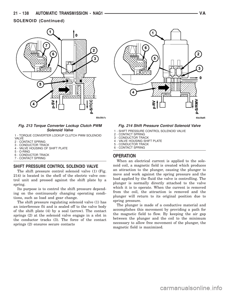
The shift pressure control solenoid valve (1) (Fig.
214) is located in the shell of the electric valve con-
trol unit and pressed against the shift plate by a
spring.
Its purpose is to control the shift pressure depend-
ing on the continuously changing operating condi-
tions, such as load and gear change.
The shift pressure regulating solenoid valve (1) has
an interference fit and is sealed off to the valve body
of the shift plate (4) by a seal (arrow). The contact
springs (2) at the solenoid valve engage in a slot in
the conductor tracks (3). The force of the contact
springs (2) ensures secure contacts
OPERATION
When an electrical current is applied to the sole-
noid coil, a magnetic field is created which produces
an attraction to the plunger, causing the plunger to
move and work against the spring pressure and the
load applied by the fluid the valve is controlling. The
plunger is normally directly attached to the valve
which it is to operate. When the current is removed
from the coil, the attraction is removed and the
plunger will return to its original position due to
spring pressure.
The plunger is made of a conductive material and
accomplishes this movement by providing a path for
the magnetic field to flow. By keeping the air gap
between the plunger and the coil to the minimum
necessary to allow free movement of the plunger, the
magnetic field is maximized.
Fig. 213 Torque Converter Lockup Clutch PWM
Solenoid Valve
1 - TORQUE CONVERTER LOCKUP CLUTCH PWM SOLENOID
VA LV E
2 - CONTACT SPRING
3 - CONDUCTOR TRACK
4 - VALVE HOUSING OF SHIFT PLATE
5 - O-RING
6 - CONDUCTOR TRACK
7 - CONTACT SPRING
Fig. 214 Shift Pressure Control Solenoid Valve
1 - SHIFT PRESSURE CONTROL SOLENOID VALVE
2 - CONTACT SPRING
3 - CONDUCTOR TRACK
4 - VALVE HOUSING SHIFT PLATE
5 - CONDUCTOR TRACK
6 - CONTACT SPRING
21 - 138 AUTOMATIC TRANSMISSION - NAG1VA
SOLENOID (Continued)