2005 MERCEDES-BENZ SPRINTER change time
[x] Cancel search: change timePage 191 of 1232
OPERATION
The multi-function indicator has several display
capabilities including odometer, trip odometer, clock,
engine oil level data, gear selector indicator
(PRNDL), certain diagnostic information and, on
vehicles so equipped, an optional Active Service SYS-
Tem (ASSYST) engine oil maintenance indicator and
an optional outside ambient temperature indicator.
The multi-function indicator is completely controlled
by the instrument cluster logic circuit, and that logic
will allow this indication to be viewed whenever the
multi-function indicator Liquid Crystal Display
(LCD) is activated. Therefore, the indicator remains
functional regardless of the ignition switch position.
With the ignition switch in the Off or Accessory posi-
tions and the key removed from the ignition lock cyl-
inder, the display is activated when the park lamps
are turned On or, for about thirty seconds after any
one of the multi-function indicator switch push but-
tons is depressed. Otherwise, the display unit is
active for about thirty seconds after the key is
inserted into the ignition lock cylinder, and inactive
about thirty seconds after the key is removed from
the ignition lock cylinder.
The multi-function indicator ªmiº (miles) or
ªkmº(kilometers) switch push button is used to con-
trol the odometer/trip odometer display modes. The
multi-function indicator clock switch push button is
used to control the clock/outside temperature display
modes. The multi-function indicator ª+º (plus) and
ª2º (minus) switch push buttons are used to adjust
the cluster general illumination dimming level, the
clock, and other cluster settings. See the owner's
manual in the vehicle glove box for more information
on the features, use, operation and setting proce-
dures for the various standard and optional multi-
function indicator displays.
Proper testing of the multi-function indicator LCD
unit, the CAN data bus and the electronic data bus
message inputs to the instrument cluster that control
some of the multi-function indicator functions
requires the use of a DRBIIItscan tool. Refer to the
appropriate diagnostic information. Additional details
for the odometer/trip odometer, the clock, the gear
selector indicator, the ambient temperature indicator
and the ASSYST warning and reminder functions of
the multi-function indicator may be found elsewhere
in this service information.
ODOMETER
DESCRIPTION
An odometer and trip odometer are standard
equipment in all instrument clusters. The odometer
and trip odometer values are displayed on the leftside of the multi-function indicator Liquid Crystal
Display (LCD). The LCD is soldered onto the cluster
electronic circuit board and is visible through a win-
dow with a clear lens located near the lower edge of
the instrument cluster, directly below the speedome-
ter. However, the odometer and trip odometer infor-
mation are not displayed simultaneously. The ªmiº
(miles) or ªkmº (kilometers) switch on the instrument
cluster circuit board toggles the display between
odometer and trip odometer modes by depressing the
switch push button that extends through the lower
edge of the cluster lens, directly below the multi-
function indicator LCD.
The odometer and trip odometer information is
stored in the instrument cluster memory. This infor-
mation can be increased when the proper inputs are
provided to the instrument cluster, but the informa-
tion cannot be decreased. The odometer can display
values up to 999,999 kilometers (999,999 miles). The
odometer latches at these values, and will not roll
over to zero. The trip odometer can display values up
to 999.9 kilometers (999.9 miles) before it rolls over
to zero. The odometer display does not have a deci-
mal point and will not show values less than a full
unit (kilometer or mile), while the trip odometer dis-
play does have a decimal point and will show tenths
of a unit (kilometer or mile). The unit of measure
(kilometers or miles) for the odometer and trip odom-
eter display is imprinted on the cluster overlay below
the left end of the LCD. The unit of measure for the
instrument cluster odometer/trip odometer is selected
at the time that it is manufactured, and cannot be
changed.
The indications of the odometer/trip odometer are
not visible when the LCD is not illuminated. When
illuminated the indications appear as dark charac-
ters silhouetted against an amber field. When the
exterior lighting is turned Off, the display is illumi-
nated at maximum brightness. When the exterior
lighting is turned On the display illumination level
can be adjusted in concert with the cluster general
illumination lighting using the plus and minus multi-
function indicator push buttons. The odometer has a
ªRental Carº mode, which will activate the multi-
function indicator LCD and illuminate the odometer
information for about thirty seconds after one of the
multi-function indicator push buttons is momentarily
depressed, or after the key is inserted into the igni-
tion switch lock cylinder with the ignition switch in
the Off position.
The odometer/trip odometer and the miles/kilome-
ters switch, and the miles/kilometers switch push
button are serviced as a unit with the instrument
cluster.
VAINSTRUMENT CLUSTER 8J - 21
MULTI-FUNCTION INDICATOR (Continued)
Page 202 of 1232
FRONT FOG LAMPS
Vehicles equipped with optional front fog lamps
have a front fog lamp relay installed in a relay
bracket located below the forward edge of the driver
side front seat cushion within the driver side front
seat riser, a fog lamp switch installed in the cluster
bezel on the instrument panel outboard of the steer-
ing column, and a fog lamp bulb installed in each of
the two front lamp units. The front fog lamps have a
path to ground at all times through their connection
to the vehicle wire harness. The headlamp switch cir-
cuitry of the left (lighting) control stalk of the multi-
function switch controls front fog lamp operation by
providing battery current to the front fog lamp relay
only when the low beam headlamps are selected. The
fog lamp switch controls front fog lamp operation by
energizing or de-energizing the front fog lamp relay
control coil.
HAZARD WARNING LAMPS
With the hazard switch in the On position, the
hazard switch button illuminates and the right and
left turn signal indicators as well as the right and
left turn signal lamps begin to flash on and off. When
the hazard warning system is activated, the hazard
switch circuitry within the multi-function switch and
the wipers, turn signals and engine start control
module electronic circuitry within the fuse block will
repeatedly energize and de-energize the turn signal
relay located in the fuse block. The turn signal relay
switches battery current from a fused B(+) fuse in
the fuse block to the turn signal indicators and the
turn signal lamps. The flashing of the hazard switch
button illumination lamp is also controlled by the
output from the turn signal relay.
HEADLAMPS
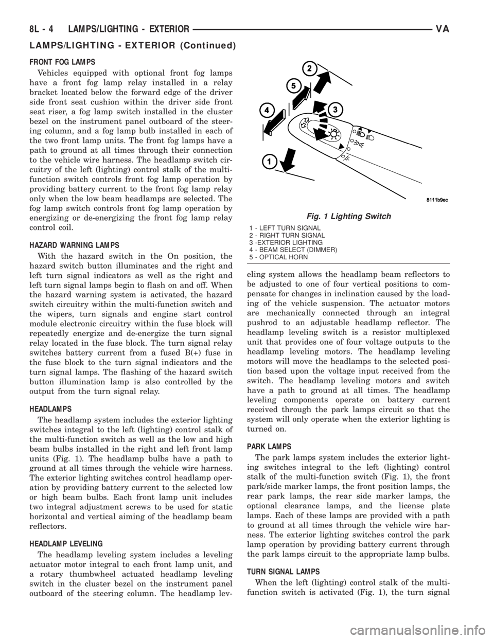
The headlamp system includes the exterior lighting
switches integral to the left (lighting) control stalk of
the multi-function switch as well as the low and high
beam bulbs installed in the right and left front lamp
units (Fig. 1). The headlamp bulbs have a path to
ground at all times through the vehicle wire harness.
The exterior lighting switches control headlamp oper-
ation by providing battery current to the selected low
or high beam bulbs. Each front lamp unit includes
two integral adjustment screws to be used for static
horizontal and vertical aiming of the headlamp beam
reflectors.
HEADLAMP LEVELING
The headlamp leveling system includes a leveling
actuator motor integral to each front lamp unit, and
a rotary thumbwheel actuated headlamp leveling
switch in the cluster bezel on the instrument panel
outboard of the steering column. The headlamp lev-eling system allows the headlamp beam reflectors to
be adjusted to one of four vertical positions to com-
pensate for changes in inclination caused by the load-
ing of the vehicle suspension. The actuator motors
are mechanically connected through an integral
pushrod to an adjustable headlamp reflector. The
headlamp leveling switch is a resistor multiplexed
unit that provides one of four voltage outputs to the
headlamp leveling motors. The headlamp leveling
motors will move the headlamps to the selected posi-
tion based upon the voltage input received from the
switch. The headlamp leveling motors and switch
have a path to ground at all times. The headlamp
leveling components operate on battery current
received through the park lamps circuit so that the
system will only operate when the exterior lighting is
turned on.
PARK LAMPS
The park lamps system includes the exterior light-
ing switches integral to the left (lighting) control
stalk of the multi-function switch (Fig. 1), the front
park/side marker lamps, the front position lamps, the
rear park lamps, the rear side marker lamps, the
optional clearance lamps, and the license plate
lamps. Each of these lamps are provided with a path
to ground at all times through the vehicle wire har-
ness. The exterior lighting switches control the park
lamp operation by providing battery current through
the park lamps circuit to the appropriate lamp bulbs.
TURN SIGNAL LAMPS
When the left (lighting) control stalk of the multi-
function switch is activated (Fig. 1), the turn signal
Fig. 1 Lighting Switch
1 - LEFT TURN SIGNAL
2 - RIGHT TURN SIGNAL
3 -EXTERIOR LIGHTING
4 - BEAM SELECT (DIMMER)
5 - OPTICAL HORN
8L - 4 LAMPS/LIGHTING - EXTERIORVA
LAMPS/LIGHTING - EXTERIOR (Continued)
Page 243 of 1232
WARNING
WARNINGS - RESTRAINT SYSTEM
WARNING: DURING AND FOLLOWING ANY SEAT
BELT SERVICE, CAREFULLY INSPECT ALL SEAT
BELTS, BUCKLES, MOUNTING HARDWARE,
RETRACTORS, TETHER STRAPS, AND ANCHORS
FOR PROPER INSTALLATION, OPERATION, OR
DAMAGE. REPLACE ANY BELT THAT IS CUT,
FRAYED, OR TORN. STRAIGHTEN ANY BELT THAT
IS TWISTED. TIGHTEN ANY LOOSE FASTENERS.
REPLACE ANY BELT THAT HAS A DAMAGED OR
INOPERATIVE BUCKLE OR RETRACTOR. REPLACE
ANY BELT THAT HAS A BENT OR DAMAGED
LATCH PLATE OR ANCHOR PLATE. NEVER
ATTEMPT TO REPAIR A SEAT BELT COMPONENT.
ALWAYS REPLACE DAMAGED OR FAULTY SEAT
BELT COMPONENTS WITH THE CORRECT, NEW
AND UNUSED REPLACEMENT PARTS LISTED IN
THE DAIMLERCHRYSLER MOPAR PARTS CATA-
LOG.
WARNING: ON VEHICLES EQUIPPED WITH AIR-
BAGS, DISABLE THE SUPPLEMENTAL RESTRAINT
SYSTEM BEFORE ATTEMPTING ANY STEERING
WHEEL, STEERING COLUMN, DRIVER AIRBAG,
PASSENGER AIRBAG, SEAT BELT TENSIONER, OR
INSTRUMENT PANEL COMPONENT DIAGNOSIS OR
SERVICE. DISCONNECT AND ISOLATE THE BAT-
TERY NEGATIVE (GROUND) CABLE, THEN WAIT
TWO MINUTES FOR THE SYSTEM CAPACITOR TO
DISCHARGE BEFORE PERFORMING FURTHER
DIAGNOSIS OR SERVICE. THIS IS THE ONLY SURE
WAY TO DISABLE THE SUPPLEMENTAL
RESTRAINT SYSTEM. FAILURE TO TAKE THE
PROPER PRECAUTIONS COULD RESULT IN ACCI-
DENTAL AIRBAG DEPLOYMENT AND POSSIBLE
PERSONAL INJURY.
WARNING: ON VEHICLES EQUIPPED WITH AIR-
BAGS, BEFORE PERFORMING ANY WELDING
OPERATIONS DISCONNECT AND ISOLATE THE
BATTERY NEGATIVE (GROUND) CABLE AND DIS-
CONNECT ALL WIRE HARNESS CONNECTORS
FROM THE AIRBAG CONTROL MODULE (ACM).
FAILURE TO TAKE THE PROPER PRECAUTIONS
COULD RESULT IN ACCIDENTAL AIRBAG DEPLOY-
MENT AND OTHER POSSIBLE DAMAGE TO THE
SUPPLEMENTAL RESTRAINT SYSTEM CIRCUITS
AND COMPONENTS.
WARNING: AN AIRBAG INFLATOR UNIT MAY CON-
TAIN SODIUM AZIDE AND POTASSIUM NITRATE.THESE MATERIALS ARE POISONOUS AND
EXTREMELY FLAMMABLE. CONTACT WITH ACID,
WATER, OR HEAVY METALS MAY PRODUCE HARM-
FUL AND IRRITATING GASES (SODIUM HYDROXIDE
IS FORMED IN THE PRESENCE OF MOISTURE) OR
COMBUSTIBLE COMPOUNDS. AN AIRBAG INFLA-
TOR UNIT MAY ALSO CONTAIN A GAS CANISTER
PRESSURIZED TO OVER 2500 PSI. DO NOT
ATTEMPT TO DISMANTLE AN AIRBAG UNIT OR
TAMPER WITH ITS INFLATOR. DO NOT PUNCTURE,
INCINERATE, OR BRING INTO CONTACT WITH
ELECTRICITY. DO NOT STORE AT TEMPERATURES
EXCEEDING 93É C (200É F).
WARNING: WHEN HANDLING A SEAT BELT TEN-
SIONER RETRACTOR, PROPER CARE SHOULD BE
EXERCISED TO KEEP FINGERS OUT FROM UNDER
THE RETRACTOR COVER AND AWAY FROM THE
SEAT BELT WEBBING WHERE IT EXITS FROM THE
RETRACTOR COVER.
WARNING: REPLACE ALL RESTRAINT SYSTEM
COMPONENTS ONLY WITH PARTS SPECIFIED IN
THE DAIMLERCHRYSLER MOPAR PARTS CATA-
LOG. SUBSTITUTE PARTS MAY APPEAR INTER-
CHANGEABLE, BUT INTERNAL DIFFERENCES MAY
RESULT IN INFERIOR OCCUPANT PROTECTION.
WARNING: THE FASTENERS, SCREWS, AND
BOLTS ORIGINALLY USED FOR THE RESTRAINT
SYSTEM COMPONENTS HAVE SPECIAL COATINGS
AND ARE SPECIFICALLY DESIGNED FOR THE
RESTRAINT SYSTEM. THEY MUST NEVER BE
REPLACED WITH ANY SUBSTITUTES. ANY TIME A
NEW FASTENER IS NEEDED, REPLACE IT WITH
THE CORRECT FASTENERS PROVIDED IN THE
SERVICE PACKAGE OR SPECIFIED IN THE
DAIMLERCHRYSLER MOPAR PARTS CATALOG.
WARNING: WHEN A STEERING COLUMN HAS AN
AIRBAG UNIT ATTACHED, NEVER PLACE THE COL-
UMN ON THE FLOOR OR ANY OTHER SURFACE
WITH THE STEERING WHEEL OR AIRBAG UNIT
FACE DOWN.
DIAGNOSIS AND TESTING - SUPPLEMENTAL
RESTRAINT SYSTEM
Proper diagnosis and testing of the supplemental
restraint system components or the Airbag Control
Module (ACM), initialization of the ACM, as well as
the retrieval or erasure of a Diagnostic Trouble Code
(DTC) from the ACM requires the use of a DRBIIIt
scan tool. Refer to the appropriate diagnostic infor-
mation.
VARESTRAINTS 8O - 5
RESTRAINTS (Continued)
Page 251 of 1232
vide access to the case mounting screws. The lower
side of the rotor hub also serves as an integral
molded plastic turn signal cancel cam.
A single connector receptacle on the upper surface
of the rotor has pigtail wires that connect to the horn
switch and the driver airbag on the steering wheel,
while a single connector receptacle on the lower sur-
face of the case has pigtail wires that connect the
clockspring to the vehicle wire harness on the steer-
ing column. Within the plastic case and wound
around the rotor spool is a long ribbon-like tape that
consists of several thin copper wire leads sandwiched
between two thin plastic membranes. The outer end
of the tape terminates at the connector receptacle
that faces the steering column, while the inner end of
the tape terminates at the connector receptacle on
the hub of the clockspring rotor that faces the steer-
ing wheel.
Service replacement clocksprings are shipped pre-
centered and with the mounting screws backed out
from the case far enough to engage the access holes
in the upper surface of the rotor. The mounting
screws secure the centered clockspring rotor to the
clockspring case during shipment, but allow free
rotation of the rotor once the clockspring is properly
installed on the steering column. (Refer to 8 - ELEC-
TRICAL/RESTRAINTS/CLOCKSPRING - STAN-
DARD PROCEDURE - CLOCKSPRING
CENTERING).
The clockspring cannot be repaired. If the clock-
spring is faulty, damaged, or if the driver airbag has
been deployed, the clockspring must be replaced.
OPERATION
The clockspring is a mechanical electrical circuit
component that is used to provide continuous electri-
cal continuity between the fixed vehicle wire harness
and the electrical components mounted on or in the
rotating steering wheel. On this model the rotating
electrical components include the driver airbag and
the horn switch. The clockspring case is positioned
and secured to the multi-function switch housing
near the top of the steering column. The connector
receptacle on the underside of the fixed clockspring
case connects the clockspring to the vehicle electrical
system through two take outs with connectors from
the vehicle wire harness.
The clockspring rotor is movable and is keyed by
integral molded ribs on the inner circumference of
the rotor hub to the splines on the external circum-
ference of the upper steering column shaft. The two
integral lobes of the turn signal cancel cam formation
on the lower surface of the clockspring rotor hub con-
tact the turn signal cancel actuator of the multi-func-
tion switch to provide automatic turn signal
cancellation. The yellow sleeved pigtail wire on theupper surface of the clockspring rotor connects the
clockspring to the driver airbag, while two single pig-
tail wires connect to the feed and ground terminals of
the horn switch located within the hub cavity of the
steering wheel.
Like the clockspring in a timepiece, the clockspring
tape has travel limits and can be damaged by being
wound too tightly during full stop-to-stop steering
wheel rotation. To prevent this from occurring, the
clockspring is centered when it is installed on the
steering column. Centering the clockspring indexes
the clockspring tape to the movable steering compo-
nents so that the tape can operate within its
designed travel limits. However, if the clockspring is
removed from the steering column or if the steering
shaft is disconnected from the steering gear, the
clockspring spool can change position relative to the
movable steering components. The clockspring must
be re-centered following completion of this service or
the tape may be damaged.
Service replacement clocksprings are shipped pre-
centered and with the mounting screws backed out
from the case far enough to engage the access holes
in the upper surface of the rotor. The mounting
screws secure the centered clockspring rotor to the
clockspring case during shipment, but allow free
rotation of the rotor once the clockspring is properly
installed on the steering column. The clockspring
mounting screws should not be tightened into the
clockspring case until the clockspring has been
installed on the steering column. If the screws are
tightened into or removed from the case before the
clockspring is installed on a steering column, the
clockspring centering procedure must be performed.
(Refer to 8 - ELECTRICAL/RESTRAINTS/CLOCK-
SPRING - STANDARD PROCEDURE - CLOCK-
SPRING CENTERING).
STANDARD PROCEDURE - CLOCKSPRING
CENTERING
The clockspring is designed to wind and unwind
when the steering wheel is rotated, but is only
designed to rotate the same number of turns (about
six to seven complete rotations) as the steering wheel
can be turned from stop to stop. Centering the clock-
spring indexes the clockspring tape to other steering
components so that it can operate within its designed
travel limits. The rotor of a centered clockspring can
be rotated three to three and one-half turns in either
direction from the centered position, without damag-
ing the clockspring tape.
However, if the clockspring is removed for service
or if the steering column is disconnected from the
steering gear, the clockspring tape can change posi-
tion relative to the other steering components. The
clockspring must then be re-centered following com-
VARESTRAINTS 8O - 13
CLOCKSPRING (Continued)
Page 257 of 1232
WARNING: USE EXTREME CARE TO PREVENT ANY
FOREIGN MATERIAL FROM ENTERING THE DRIVER
AIRBAG, OR BECOMING ENTRAPPED BETWEEN
THE DRIVER AIRBAG CUSHION AND THE DRIVER
AIRBAG TRIM COVER. FAILURE TO OBSERVE THIS
WARNING COULD RESULT IN OCCUPANT INJURIES
UPON AIRBAG DEPLOYMENT.
WARNING: THE DRIVER AIRBAG TRIM COVER
MUST NEVER BE PAINTED. REPLACEMENT AIR-
BAGS ARE SERVICED WITH TRIM COVERS IN THE
ORIGINAL COLORS. PAINT MAY CHANGE THE WAY
IN WHICH THE MATERIAL OF THE TRIM COVER
RESPONDS TO AN AIRBAG DEPLOYMENT. FAIL-
URE TO OBSERVE THIS WARNING COULD RESULT
IN OCCUPANT INJURIES UPON AIRBAG DEPLOY-
MENT.
(1) Position the driver airbag close enough to the
steering wheel to reconnect the clockspring driver
airbag pigtail wire connector at the back of the air-
bag housing.
(2) When installing the driver airbag, reconnect
the clockspring driver airbag pigtail wire connector
to the airbag inflator connector receptacle by press-
ing straight in on the connector (Fig. 21). You can be
certain that the connector is fully engaged by listen-
ing carefully for a distinct, audible click as the con-
nector snaps into place.
(3) Carefully position the driver airbag in the
steering wheel. Be certain that the clockspring pig-
tail wire and horn switch wires in the steering wheel
hub area are not pinched between the driver airbag
and the horn switch armature.
(4) From the underside of the steering wheel,
install and tighten the two screws that secure the
driver airbag to the horn switch armature within the
hub cavity of the steering wheel. Tighten the screws
to 6 N´m (53 in. lbs.).
(5) Do not reconnect the battery negative cable at
this time. The supplemental restraint system verifi-
cation test procedure should be performed following
service of any supplemental restraint system compo-
nent. (Refer to 8 - ELECTRICAL/RESTRAINTS -
STANDARD PROCEDURE - VERIFICATION TEST).
FRONT SEAT BELT &
RETRACTOR
REMOVAL
The following procedure is for replacement of a
faulty or damaged front seat belt and retractor unit,
which includes a seat belt tensioner for the driver
side as standard equipment. Vehicles equipped withan optional passenger airbag also have a seat belt
tensioner for the passenger side. (Refer to 8 - ELEC-
TRICAL/RESTRAINTS/SEAT BELT TENSIONER -
DESCRIPTION). If the seat belt or retractor is faulty
or damaged, but the seat belt tensioner is not
deployed, review the recommended procedures for
handling non-deployed supplemental restraints.
(Refer to 8 - ELECTRICAL/RESTRAINTS - STAN-
DARD PROCEDURE - HANDLING NON-DE-
PLOYED SUPPLEMENTAL RESTRAINTS). If the
seat belt tensioner has been deployed, review the rec-
ommended procedures for service after a supplemen-
tal restraint deployment before removing the front
seat belt and retractor from the vehicle. (Refer to 8 -
ELECTRICAL/RESTRAINTS - STANDARD PROCE-
DURE - SERVICE AFTER A SUPPLEMENTAL
RESTRAINT DEPLOYMENT).
WARNING: ON VEHICLES EQUIPPED WITH AIR-
BAGS, DISABLE THE SUPPLEMENTAL RESTRAINT
SYSTEM BEFORE ATTEMPTING ANY STEERING
WHEEL, STEERING COLUMN, DRIVER AIRBAG,
PASSENGER AIRBAG, SEAT BELT TENSIONER, OR
INSTRUMENT PANEL COMPONENT DIAGNOSIS OR
SERVICE. DISCONNECT AND ISOLATE THE BAT-
TERY NEGATIVE (GROUND) CABLE, THEN WAIT
TWO MINUTES FOR THE SYSTEM CAPACITOR TO
DISCHARGE BEFORE PERFORMING FURTHER
DIAGNOSIS OR SERVICE. THIS IS THE ONLY SURE
WAY TO DISABLE THE SUPPLEMENTAL
RESTRAINT SYSTEM. FAILURE TO TAKE THE
PROPER PRECAUTIONS COULD RESULT IN ACCI-
DENTAL AIRBAG DEPLOYMENT AND POSSIBLE
PERSONAL INJURY.
WARNING: DURING AND FOLLOWING ANY SEAT
BELT SERVICE, CAREFULLY INSPECT ALL SEAT
BELTS, BUCKLES, MOUNTING HARDWARE,
RETRACTORS, AND ANCHORS FOR PROPER
INSTALLATION, OPERATION, OR DAMAGE.
REPLACE ANY BELT THAT IS CUT, FRAYED, OR
TORN. STRAIGHTEN ANY BELT THAT IS TWISTED.
TIGHTEN ANY LOOSE FASTENERS. REPLACE ANY
BELT THAT HAS A DAMAGED OR INOPERATIVE
BUCKLE OR RETRACTOR. REPLACE ANY BELT
THAT HAS A BENT OR DAMAGED LATCH PLATE
OR ANCHOR PLATE. NEVER ATTEMPT TO REPAIR
A SEAT BELT COMPONENT. ALWAYS REPLACE
DAMAGED OR FAULTY SEAT BELT COMPONENTS
WITH THE CORRECT, NEW AND UNUSED
REPLACEMENT PARTS LISTED IN THE
DAIMLERCHRYSLER MOPAR PARTS CATALOG.
(1) Move the front seat to its most forward position
for easiest access to the B-pillar trim.
VARESTRAINTS 8O - 19
DRIVER AIRBAG (Continued)
Page 264 of 1232
INSTALLATION
The following procedure is for replacement of a
faulty or damaged passenger airbag. If the airbag is
faulty or damaged, but not deployed, review the rec-
ommended procedures for handling non-deployed
supplemental restraints. (Refer to 8 - ELECTRICAL/
RESTRAINTS - STANDARD PROCEDURE - HAN-
DLING NON-DEPLOYED SUPPLEMENTAL
RESTRAINTS). If the passenger airbag has been
deployed, review the recommended procedures for
service after a supplemental restraint deployment
before removing the airbag from the vehicle. (Refer to
8 - ELECTRICAL/RESTRAINTS - STANDARD PRO-
CEDURE - SERVICE AFTER A SUPPLEMENTAL
RESTRAINT DEPLOYMENT).
WARNING: ON VEHICLES EQUIPPED WITH AIR-
BAGS, DISABLE THE SUPPLEMENTAL RESTRAINT
SYSTEM BEFORE ATTEMPTING ANY STEERING
WHEEL, STEERING COLUMN, DRIVER AIRBAG,
PASSENGER AIRBAG, SEAT BELT TENSIONER, OR
INSTRUMENT PANEL COMPONENT DIAGNOSIS OR
SERVICE. DISCONNECT AND ISOLATE THE BAT-
TERY NEGATIVE (GROUND) CABLE, THEN WAIT
TWO MINUTES FOR THE SYSTEM CAPACITOR TO
DISCHARGE BEFORE PERFORMING FURTHER
DIAGNOSIS OR SERVICE. THIS IS THE ONLY SURE
WAY TO DISABLE THE SUPPLEMENTAL
RESTRAINT SYSTEM. FAILURE TO TAKE THE
PROPER PRECAUTIONS COULD RESULT IN ACCI-
DENTAL AIRBAG DEPLOYMENT AND POSSIBLE
PERSONAL INJURY.
WARNING: WHEN REMOVING A DEPLOYED AIR-
BAG, RUBBER GLOVES, EYE PROTECTION, AND A
LONG-SLEEVED SHIRT SHOULD BE WORN. THERE
MAY BE DEPOSITS ON THE AIRBAG UNIT AND
OTHER INTERIOR SURFACES. IN LARGE DOSES,
THESE DEPOSITS MAY CAUSE IRRITATION TO THE
SKIN AND EYES.
WARNING: USE EXTREME CARE TO PREVENT ANY
FOREIGN MATERIAL FROM ENTERING THE PAS-
SENGER AIRBAG, OR BECOMING ENTRAPPED
BETWEEN THE PASSENGER AIRBAG CUSHION
AND THE PASSENGER AIRBAG DOOR. FAILURE TO
OBSERVE THIS WARNING COULD RESULT IN
OCCUPANT INJURIES UPON AIRBAG DEPLOY-
MENT.WARNING: THE PASSENGER AIRBAG DOOR MUST
NEVER BE PAINTED. REPLACEMENT PASSENGER
AIRBAGS ARE SERVICED WITH DOORS IN THE
ORIGINAL COLORS. PAINT MAY CHANGE THE WAY
IN WHICH THE MATERIAL OF THE AIRBAG DOOR
RESPONDS TO AN AIRBAG DEPLOYMENT. FAIL-
URE TO OBSERVE THIS WARNING COULD RESULT
IN OCCUPANT INJURIES UPON AIRBAG DEPLOY-
MENT.
(1) Carefully position the passenger airbag and
airbag door unit to the instrument panel (Fig. 29).
(2) When installing the passenger airbag, recon-
nect the vehicle wire harness connector to the airbag
inflator connector receptacle by pressing straight in
on the connector. You can be certain that the connec-
tor is fully engaged by listening carefully for a dis-
tinct, audible click as the connector snaps into place.
(3) Push the passenger airbag unit forward far
enough to engage the lower edge of the airbag door
with the two lower clips in the instrument panel.
(4) Install and tighten the two screws that secure
the flange of the passenger airbag housing to the
bracket on the instrument panel structural support.
Tighten the screws to 10 N´m (89 in. lbs.).
(5) Install and tighten the two screws that secure
the passenger airbag door upper clips to the instru-
ment panel base trim. Tighten the screws to 2 N´m
(18 in. lbs.).
(6) Reinstall the instrument panel top cover tray
onto the instrument panel. (Refer to 23 - BODY/IN-
STRUMENT PANEL/INSTRUMENT PANEL TOP
COVER - TRAY - INSTALLATION).
(7) Do not reconnect the battery negative cable at
this time. The supplemental restraint system verifi-
cation test procedure should be performed following
service of any supplemental restraint system compo-
nent. (Refer to 8 - ELECTRICAL/RESTRAINTS -
STANDARD PROCEDURE - VERIFICATION TEST).
8O - 26 RESTRAINTSVA
PASSENGER AIRBAG (Continued)
Page 297 of 1232
evenly over the wiper pivot shaft. Gently lower the
wiper arm until the wiper blade rests on the glass.
(3) Install and tighten the nut that secures the
wiper arm to the wiper pivot shaft. Tighten the nut
to 24 N´m (18 ft. lbs.).
(4) Wet the windshield glass, then operate the wip-
ers. Move the right (wiper) control stalk of the multi-
function switch to the Off position, then check for the
correct wiper arm position and readjust as required.
(5) Engage the pivot cover with the wiper arm
hinge pin, then push the pivot end of the cover down
firmly and evenly until it snaps over the wiper blade
pivot end.
(6) Reconnect the washer nozzle hose to the elbow
fitting on the cowl top panel near the pivot end of the
wiper arm.
WIPER BLADE
DESCRIPTION
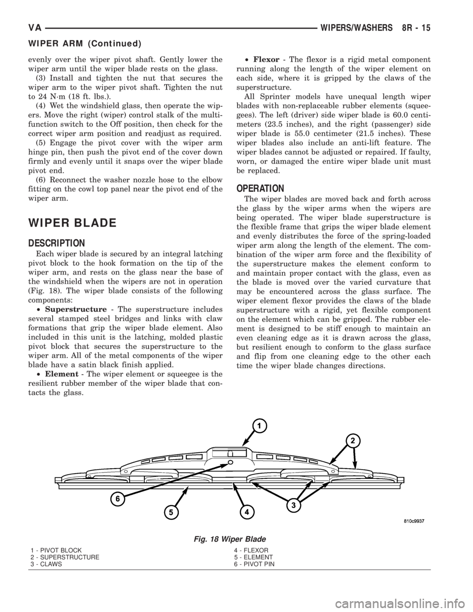
Each wiper blade is secured by an integral latching
pivot block to the hook formation on the tip of the
wiper arm, and rests on the glass near the base of
the windshield when the wipers are not in operation
(Fig. 18). The wiper blade consists of the following
components:
²Superstructure- The superstructure includes
several stamped steel bridges and links with claw
formations that grip the wiper blade element. Also
included in this unit is the latching, molded plastic
pivot block that secures the superstructure to the
wiper arm. All of the metal components of the wiper
blade have a satin black finish applied.
²Element- The wiper element or squeegee is the
resilient rubber member of the wiper blade that con-
tacts the glass.²Flexor- The flexor is a rigid metal component
running along the length of the wiper element on
each side, where it is gripped by the claws of the
superstructure.
All Sprinter models have unequal length wiper
blades with non-replaceable rubber elements (squee-
gees). The left (driver) side wiper blade is 60.0 centi-
meters (23.5 inches), and the right (passenger) side
wiper blade is 55.0 centimeter (21.5 inches). These
wiper blades also include an anti-lift feature. The
wiper blades cannot be adjusted or repaired. If faulty,
worn, or damaged the entire wiper blade unit must
be replaced.
OPERATION
The wiper blades are moved back and forth across
the glass by the wiper arms when the wipers are
being operated. The wiper blade superstructure is
the flexible frame that grips the wiper blade element
and evenly distributes the force of the spring-loaded
wiper arm along the length of the element. The com-
bination of the wiper arm force and the flexibility of
the superstructure makes the element conform to
and maintain proper contact with the glass, even as
the blade is moved over the varied curvature that
may be encountered across the glass surface. The
wiper element flexor provides the claws of the blade
superstructure with a rigid, yet flexible component
on the element which can be gripped. The rubber ele-
ment is designed to be stiff enough to maintain an
even cleaning edge as it is drawn across the glass,
but resilient enough to conform to the glass surface
and flip from one cleaning edge to the other each
time the wiper blade changes directions.
Fig. 18 Wiper Blade
1 - PIVOT BLOCK 4 - FLEXOR
2 - SUPERSTRUCTURE 5 - ELEMENT
3 - CLAWS 6 - PIVOT PIN
VAWIPERS/WASHERS 8R - 15
WIPER ARM (Continued)
Page 317 of 1232
8W-02 COMPONENT INDEX
Component Page
A/C Auxiliary Fan Relay................ 8W-42
A/C Auxiliary Fan..................... 8W-42
A/C Compressor Clutch................. 8W-42
A/C Control Module-Roof................ 8W-42
A/C Fan Switch....................... 8W-42
A/C Switch-Roof...................... 8W-42
Accelerator Pedal Position Sensor......... 8W-30
Air Outlet Temperature Sensor........... 8W-42
Airbag Control Module................. 8W-43
Airbag Squibs........................ 8W-43
Ambient Temperature Sensor............ 8W-42
Ash Receiver Lamp.................... 8W-44
Automatic Temperature Control Module.... 8W-42
Auxiliary Heater Relay................. 8W-42
Auxiliary Heater Switch................ 8W-42
Battery Relay-Auxiliary................ 8W-20
Batteries............................ 8W-20
Beam Select Switch.................... 8W-50
Blower Motors........................ 8W-42
Body Plug Connector................... 8W-11
Boost Pressure Sensor.................. 8W-30
Boost Pressure Solenoid................ 8W-30
Brake Fluid Level Switch............... 8W-35
Brake Lamp Switch.................... 8W-35
Brake Wear Sensors................... 8W-35
Cabin Heater Assembly................. 8W-42
Cabin Heater Control Module............ 8W-42
Camshaft Position Sensor............... 8W-30
Center High Mounted Stop Lamp......... 8W-51
Central Timer Module.................. 8W-45
Cigar Lighter Lamp................... 8W-44
Cigar Lighter......................... 8W-41
Circulation Pump Diode................ 8W-42
Circulation Pump Relay................ 8W-42
Circulation Pump..................... 8W-42
Clockspring....................... 8W-41, 43
Contact Switch Door-Tailgate............ 8W-44
Controller Antilock Brake............... 8W-35
Courtesy Lamps...................... 8W-44
Crankcase Heater..................... 8W-30
Crankshaft Position Sensor.............. 8W-30
Ctel Antenna Connector................ 8W-55
Ctel Connector..................... 8W-47, 55
Cylinder Lock Switch-Driver............. 8W-61
D+ Relay No. 1....................... 8W-10
D+ Relay No. 2....................... 8W-11
Data Link Connector................... 8W-18
Daytime Running Lamp Relays........... 8W-50
Differential Lock Solenoid Valve.......... 8W-31
Dome Lamp.......................... 8W-44
Door Jamb Switches................... 8W-44
Door Lock Motor/Ajar Switch Assemblies . . . 8W-61Component Page
Dosing Pump......................... 8W-42
EGR Valve........................... 8W-30
Engine Control Module................. 8W-30
Engine Control Relay.................. 8W-31
Engine Coolant Level Switch............. 8W-30
Engine Coolant Temperature Sensor....... 8W-30
Engine Oil Sensor..................... 8W-30
Evaporator Temperature Sensor.......... 8W-42
Fan Stage 1 Relay..................... 8W-42
Fog Lamp Relay...................... 8W-50
Fog Lamp Switch..................... 8W-50
Fuel Injectors........................ 8W-30
Fuel Level Sensor..................... 8W-30
Fuel Pressure Sensor.................. 8W-30
Fuel Pressure Solenoid................. 8W-30
Fuel Shutdown Solenoid................ 8W-30
Fuel Temperature Sensor............... 8W-30
Fuses............................ 8W-10, 11
Fuse Blocks.......................... 8W-10
Fuse/Relay Block...................... 8W-11
Fused Ignition Switch Run-Start Relay..... 8W-11
Grounds............................ 8W-70
Generator........................... 8W-20
Glow Plug Control Module.............. 8W-30
Glow Plugs.......................... 8W-30
Hazard Warning Switch................ 8W-52
Headlamp Adjust Switch................ 8W-50
Headlamp Assemblies............... 8W-50, 52
Headlamp Switch..................... 8W-50
Heat Exchanger Connector.............. 8W-42
Heat Exchanger Switch................. 8W-42
Heated Seat Modules.................. 8W-63
Heated Seat Switches.................. 8W-63
Heater Timer-Auxiliary................. 8W-42
Hood Ajar Switch..................... 8W-39
Horn Relay.......................... 8W-41
Horn Switch......................... 8W-41
Horn............................... 8W-41
Ignition Lock Switch................... 8W-40
Ignition Switch....................... 8W-10
Instrument Cluster.................... 8W-40
Instrument Panel Socket................ 8W-40
Intake Air Temperature Sensor........... 8W-30
Interior Lamps....................... 8W-44
Interior Light Switches................. 8W-44
Interior Lighting Connector.............. 8W-44
Intrusion Sensors..................... 8W-39
Kickdown Switch...................... 8W-30
Lamp Relays......................... 8W-50
License Plate Lamps................... 8W-51
Locker Switches...................... 8W-31
Low Fuel Pressure Sensor............... 8W-30
VA8W-02 COMPONENT INDEX 8W - 02 - 1