2005 MERCEDES-BENZ SPRINTER key
[x] Cancel search: keyPage 16 of 1232
JUMP STARTING
STANDARD PROCEDURE - JUMP STARTING
WARNING: REVIEW ALL SAFETY PRECAUTIONS
AND WARNINGS IN THE BATTERY SYSTEM SEC-
TION OF THE SERVICE MANUAL. (Refer to 8 -
ELECTRICAL/BATTERY SYSTEM/BATTERY - STAN-
DARD PROCEDURE)
²DO NOT JUMP START A FROZEN BATTERY,
PERSONAL INJURY CAN RESULT.
²IF EQUIPPED, DO NOT JUMP START WHEN
MAINTENANCE FREE BATTERY INDICATOR DOT IS
YELLOW OR BRIGHT COLOR.
²DO NOT JUMP START A VEHICLE WHEN THE
BATTERY FLUID IS BELOW THE TOP OF LEAD
PLATES.
²DO NOT ALLOW JUMPER CABLE CLAMPS TO
TOUCH EACH OTHER WHEN CONNECTED TO A
BOOSTER SOURCE.
²DO NOT USE OPEN FLAME NEAR BATTERY.
²REMOVE METALLIC JEWELRY WORN ON
HANDS OR WRISTS TO AVOID INJURY BY ACCI-
DENTAL ARCING OF BATTERY CURRENT.
²WHEN USING A HIGH OUTPUT BOOSTING
DEVICE, DO NOT ALLOW BATTERY VOLTAGE TO
EXCEED 16 VOLTS. REFER TO INSTRUCTIONS
PROVIDED WITH DEVICE BEING USED.
FAILURE TO FOLLOW THESE INSTRUCTIONS MAY
RESULT IN PERSONAL INJURY.
CAUTION: When using another vehicle as a
booster, do not allow vehicles to touch. Electrical
systems can be damaged on either vehicle.
TO JUMP START A DISABLED VEHICLE:
(1) Raise hood on disabled vehicle and visually
inspect engine compartment for:
²Battery cable clamp condition, clean if necessary.
²Frozen battery.
²Yellow or bright color test indicator, if equipped.
²Low battery fluid level.
²Generator drive belt condition and tension.
²Fuel fumes or leakage, correct if necessary.
CAUTION: If the cause of starting problem on dis-
abled vehicle is severe, damage to booster vehicle
charging system can result.
(2) When using another vehicle as a booster
source, park the booster vehicle within cable reach.
Turn off all accessories, set the parking brake, place
the automatic transmission in PARK or the manual
transmission in NEUTRAL and turn the ignition
OFF.(3) On disabled vehicle, place gear selector in park
or neutral and set park brake. Turn off all accesso-
ries.
(4) Connect jumper cables to booster battery. RED
clamp to positive terminal (+). BLACK clamp to neg-
ative terminal (-). DO NOT allow clamps at opposite
end of cables to touch, electrical arc will result.
Review all warnings in this procedure.
(5) On disabled vehicle, connect RED jumper cable
clamp to positive (+) terminal. Connect BLACK
jumper cable clamp to engine ground as close to the
ground cable attaching point as possible.
(6) Start the engine in the vehicle which has the
booster battery, let the engine idle a few minutes,
then start the engine in the vehicle with the dis-
charged battery.
CAUTION: Do not crank starter motor on disabled
vehicle for more than 15 seconds, starter will over-
heat and could fail.
(7) Allow battery in disabled vehicle to charge to
at least 12.4 volts (75% charge) before attempting to
start engine. If engine does not start within 15 sec-
onds, stop cranking engine and allow starter to cool
(15 min.), before cranking again.
DISCONNECT CABLE CLAMPS AS FOLLOWS:
²Disconnect BLACK cable clamp from engine
ground on disabled vehicle.
²When using a Booster vehicle, disconnect
BLACK cable clamp from battery negative terminal.
Disconnect RED cable clamp from battery positive
terminal.
²Disconnect RED cable clamp from battery posi-
tive terminal on disabled vehicle.
TOWING
STANDARD PROCEDURE - TOWING
WARNING: Do not tow the vehicle if the key cannot
be turned in the ignition lock. If the key cannot be
turned, the ignition lock remains locked and the
vehicle cannot be steered. With the engine not run-
ning there is no power assistance for the braking
and steering systems. In this case, it is important to
keep in mind that a considerably higher degree of
effort is necessary to brake and steer the vehicle.
The vehicle must not be towed with the front axle
raised and the key in position 2 in the ignition lock
as the drive wheels could then lock due to the
acceleration skid control (ASR)
0 - 6 LUBRICATION & MAINTENANCEVA
Page 17 of 1232
If the Engine is Damaged
For towing distances up to 30 miles (about 50
km)
²Shift selector lever in ªNº position.
²Do not exceed a towing speed of 30 m.p.h. (50
km/h).
For towing distances greater than 30 mile
(about 50 km)
²Remove the propeller shafts leading to the drive
axles. The vehicle can be towed without restriction.
If the Transmission is Damaged
²Remove the propeller shafts leading to the drive
axles. The vehicle can be towed without restriction.
If the Front Axle is Damaged
²Raise the front axle.
²Observe the same towing restrictions as for
engine damage.
If the Rear Axle is Damaged
²Raise the rear axle.
NOTE: Comply with local legal regulations regard-
ing towing vehicles.
SAFETY PRECAUTIONS
NOTE: The following safety precautions must be
observed when towing a vehicle.
²Secure loose and protruding parts.
²Always use a safety chain system that is inde-
pendent of the lifting and towing equipment.
²Do not allow towing equipment to contact the
disabled vehicle's fuel tank.
²Do not allow anyone under the disabled vehicle
while it is lifted by the towing device.
²Do not allow passengers to ride in a vehicle
being towed.
²Always observe state and local laws regarding
towing regulations.
²Do not tow a vehicle in a manner that could
jeopardize the safety of the operator, pedestrians or
other motorists.
²Do not attach tow chains, T-hooks, J-hooks, or a
tow sling to a bumper, steering linkage, drive shafts
or a non-reinforced frame hole.
²Remove exhaust pipe tips that interfere with the
tow sling and crossbar
²Padding should be placed between the tow sling/
crossbar and any painted surfaces
²When placing tow hooks on the rear axle, posi-
tion them so they do not damage the brake tubing or
hoses²Do not tow the vehicle by connecting to the front
or rear shock absorbers
²Do not tow a heavily loaded vehicle. Damage to
the vehicle may result. Use a flatbed device to trans-
port a loaded vehicle.
GROUND CLEARANCE
CAUTION: If vehicle is towed with wheels removed,
install lug nuts to retain brake drums.
A towed vehicle should be raised until lifted wheels
are a minimum 100 mm (4 in) from the ground. Be
sure there is adequate ground clearance at the oppo-
site end of the vehicle, especially when towing over
rough terrain, steep rises in the road or if the vehicle
is equipped with air dams, spoilers, and/or ground
effect panels. If necessary, remove the wheels from
the lifted end of the vehicle and lower the vehicle
closer to the ground, to increase the ground clearance
at the opposite end of the vehicle. Install lug nuts on
wheel attaching studs to retain brake drums.
RAMP ANGLE
If a vehicle with flat-bed towing equipment is used,
the approach ramp angle should not exceed 15
degrees.
TOWING WHEN KEYS ARE NOT AVAILABLE
When the vehicle is locked and keys are not avail-
able, use a flat bed hauler. A Wheel-lift or Sling-type
device can be used provided all the wheels are lifted
off the ground using tow dollies.
MAINTENANCE SCHEDULES
DESCRIPTION
The use of Special lubricant additives is not recom-
mended. The use of such additives may affect the
warranty rights. With regard to legal stipulations
concerning emissions control, please note that
engines have to be serviced and adjusted in accor-
dance with special instructions and using special
measuring equipment. Modifications to or interfer-
ence with the emissions control systems are not per-
missible.
MAINTENANCE - WITHOUT ASSYST
MAINTENANCE COMPUTER
Maintenance Intervals
²Oil service ±Normal Operationevery 10,000
miles or 16,000 km or 12 months.
²Maintenance service every 20,000 miles or
32,000 km.
Additional work must be carried out at yearly
intervals.
VALUBRICATION & MAINTENANCE 0 - 7
TOWING (Continued)
Page 120 of 1232
²Lights-On Warning- The EMIC chime tone
generator will generate repetitive chime tones at a
fast rate when either front door is opened with the
ignition switch in any position except On, and the
exterior lights are turned On. The EMIC uses inter-
nal programming and hard wired inputs from the left
(lighting) control stalk of the multi-function switch,
the ignition switch, and both front door jamb
switches to determine the current status of these
switches. This chime will continue to sound until the
exterior lighting is turned Off, until the ignition
switch is turned to the On position, or until both
front doors are closed, whichever occurs first.
²Key-In-Ignition Warning-
The EMIC chime
tone generator will generate repetitive chime tones at a
fast rate when the key is in the ignition lock cylinder,
the ignition switch is in any position except On, and
either front door is opened. The EMIC uses internal
programming and hard wired inputs from the key-in
ignition switch, the ignition switch, and both front door
jamb switches to determine the current status of these
switches. The chime will continue to sound until the key
is removed from the ignition lock cylinder, until the
ignition switch is turned to the On position, or until
both front doors are closed, whichever occurs first.
²Audible Turn Signal/Hazard Warning Sup-
port-
The EMIC contactless relay will generate repeti-
tive clicks at a slow rate during normal turn signal/
hazard warning operation, or at a fast rate when a turn
signal lamp bulb or circuit is inoperative, in concert with
the operation of the turn signal indicators in the cluster.
These clicks are designed to emulate the sound of the
opening and closing of the contact points in a conven-
tional electro-mechanical turn signal or hazard warning
flasher. The EMIC uses a hard wired input received from
the turn signal relay in the fuse block beneath the steer-
ing column through the turn signal or hazard warning
switch circuitry of the multi-function switch to determine
when to flash the turn signal indicators and activate the
contactless relay on the cluster electronic circuit board.
The turn signal clicks will continue to sound until the
turn signal switch is turned Off, or until the ignition
switch is turned to the Off position, whichever occurs
first. The hazard warning clicks will continue to sound
until the hazard warning switch is turned Off.
The EMIC provides chime service for all available
features in the chime warning system. The EMIC relies
upon its internal programming and hard wired inputs
from the front door ajar switches, the key-in ignition
switch, the ignition switch, the seat belt switch, and the
turn signal/hazard warning (multi-function) switches.
The EMIC relies upon electronic message inputs
received from other electronic modules over the CAN
data bus network to provide chime service for the low
engine oil level warning. Upon receiving the proper
inputs, the EMIC activates the chime tone generator orthe contactless relay to provide the audible warning to
the vehicle operator. The internal programming of the
EMIC determines the priority of each chime request
input that is received, as well as the rate and duration
of each tone that is to be generated. See the owner's
manual in the vehicle glove box for more information on
the features provided by the chime warning system.
The hard wired chime warning system inputs to
the EMIC, as well as other hard wired circuits for
this system may be diagnosed and tested using con-
ventional diagnostic tools and procedures. However,
conventional diagnostic methods may not prove con-
clusive in the diagnosis of the EMIC, the CAN data
bus network, or the electronic message inputs used
by the EMIC to provide chime warning system ser-
vice. The most reliable, efficient, and accurate means
to diagnose the EMIC, the CAN data bus network,
and the electronic message inputs for the chime
warning system requires the use of a DRBIIItscan
tool. Refer to the appropriate diagnostic information.
DIAGNOSIS AND TESTING - CHIME WARNING
SYSTEM
WARNING: ON VEHICLES EQUIPPED WITH AIRBAGS,
DISABLE THE SUPPLEMENTAL RESTRAINT SYSTEM
BEFORE ATTEMPTING ANY STEERING WHEEL,
STEERING COLUMN, DRIVER AIRBAG, PASSENGER
AIRBAG, SEAT BELT TENSIONER, OR INSTRUMENT
PANEL COMPONENT DIAGNOSIS OR SERVICE. DIS-
CONNECT AND ISOLATE THE BATTERY NEGATIVE
(GROUND) CABLE, THEN WAIT TWO MINUTES FOR
THE SYSTEM CAPACITOR TO DISCHARGE BEFORE
PERFORMING FURTHER DIAGNOSIS OR SERVICE.
THIS IS THE ONLY SURE WAY TO DISABLE THE SUP-
PLEMENTAL RESTRAINT SYSTEM. FAILURE TO TAKE
THE PROPER PRECAUTIONS COULD RESULT IN
ACCIDENTAL AIRBAG DEPLOYMENT AND POSSIBLE
PERSONAL INJURY.
The hard wired chime warning system inputs to
the Electro-Mechanical Instrument Cluster (EMIC),
as well as other hard wired circuits for this system
may be diagnosed and tested using conventional
diagnostic tools and procedures. However, conven-
tional diagnostic methods may not prove conclusive
in the diagnosis of the EMIC, the Controller Area
Network (CAN) data bus network, or the electronic
message inputs used by the EMIC to provide chime
warning system service. The most reliable, efficient,
and accurate means to diagnose the EMIC, the CAN
data bus network, and the electronic message inputs
for the chime warning system requires the use of a
DRBIIItscan tool. Refer to the appropriate diagnos-
tic information.
8B - 2 CHIME/BUZZERVA
CHIME/BUZZER (Continued)
Page 121 of 1232
ELECTRONIC CONTROL MODULES
TABLE OF CONTENTS
page page
CENTRAL TIMER MODULE
DESCRIPTION..........................1
OPERATION............................2
DIAGNOSIS AND TESTING - CENTRAL TIMER
MODULE.............................2
REMOVAL.............................2
INSTALLATION..........................2
CONTROLLER ANTILOCK BRAKE
DESCRIPTION..........................3
REMOVAL.............................3INSTALLATION..........................3
ENGINE CONTROL MODULE
DESCRIPTION..........................3
REMOVAL.............................4
INSTALLATION..........................4
TRANSMISSION CONTROL MODULE
DESCRIPTION..........................5
OPERATION............................5
STANDARD PROCEDURE - TCM ADAPTATION . 8
CENTRAL TIMER MODULE
DESCRIPTION
The central timer module (CTM) is located beneath
the driver seat. The CTM uses information carried on
the programmable communications interface (PCI)
data bus network along with many hard wired inputs
to monitor many sensor and switch inputs. In
response to those inputs, the circuitry and program-
ming of the CTM allow it to supply the vehicle occu-
pants with audible and visual information, and to
control and integrate many functions and features of
the vehicle through both hard wired outputs and the
transmission of message outputs to other modules in
the vehicle over the PCI data bus.
The features that the CTM supports or controls
include the following:
²Central Locking- The CTM on vehicles
equipped with the optional Vehicle Theft Security
System (VTSS) includes a central locking/unlocking
feature.
²Enhanced Accident Response- The CTM pro-
vides an optional enhanced accident response fea-
ture. This is a programmable feature.
²Panic Mode- The CTM provides support for
the optional RKE system panic mode including horn,
headlamp, and park lamp flash features.
²Power Lock Control- The CTM provides the
optional power lock system features, including sup-
port for the automatic door lock and door lock inhibit
modes.²Programmable Features- The CTM provides
support for certain programmable features.
²Remote Keyless Entry- The CTM provides
the optional Remote Keyless Entry (RKE) system fea-
tures, including support for the RKE Lock (with
optional horn and park lamps flash), Unlock (with
park lamps flash, driver-door-only unlock, and
unlock-all-doors), Panic, and illuminated entry
modes, as well as the ability to be programmed to
recognize up to four RKE transmitters. The RKE
horn, driver-door-only unlock, and unlock-all-doors
features are programmable.
²Vehicle Theft Security System- The CTM
provides control of the optional Vehicle Theft Secu-
rity System (VTSS) features, including support for
the central locking/unlocking mode and control of the
Security indicator in the instrument cluster.
Hard wired circuitry connects the CTM to the elec-
trical system of the vehicle. Refer to the appropriate
wiring information.
Many of the features in the vehicle controlled or
supported by the CTM are programmable using the
DRBIIItscan tool. However, if any of the CTM hard-
ware components are damaged or faulty, the entire
CTM unit must be replaced. The hard wired inputs
or outputs of all CTM versions can be diagnosed
using conventional diagnostic tools and methods;
however, for diagnosis of the CTM or the PCI data
bus, the use of a DRBIIItscan tool is required. Refer
to the appropriate diagnostic information.
VAELECTRONIC CONTROL MODULES 8E - 1
Page 122 of 1232
OPERATION
The central timer module (CTM) monitors many
hard wired switch and sensor inputs as well as those
resources it shares with other modules in the vehicle
through its communication over the programmable
communications interface (PCI) data bus network.
The internal programming and all of these inputs
allow the CTM to determine the tasks it needs to
perform and their priorities, as well as both the stan-
dard and optional features that it should provide.
The CTM then performs those tasks and provides
those features through both PCI data bus communi-
cation with other modules and hard wired outputs
through a number of driver circuits, relays, and
actuators.These outputs allow the CTM the ability to
control numerous accessory systems in the vehicle.
The CTM monitors its own internal circuitry as
well as many of its input and output circuits, and
will store a Diagnostic Trouble Code (DTC) in elec-
tronic memory for any failure it detects. These DTCs
can be retrieved and diagnosed using a DRBIIItscan
tool. Refer to the appropriate diagnostic information.
HARD WIRED INPUTS
The hard wired inputs to the CTM include the fol-
lowing:
²Fused B(+)
²Fused ignition switch output (run-acc)
²Fused ignition switch output (run-start)
²Ground
²Key-in ignition switch sense
²Sliding door switch sense
²Passenger door switch sense
²Driver door switch sense
²PCI bus circuit
HARD WIRED OUTPUTS
The hard wired outputs of the CTM include the fol-
lowing:
²Door lock relay output
²Door unlock relay output
²VTSS indicator driver
MESSAGING
The CTM uses the following messages received
from other electronic modules over the PCI data bus:
²Airbag Deploy (ACM)
²Beep request (CMTC)
²Charging System Failure (PCM)
²Chime request (EMIC)
²Engine RPM (PCM)
²OK to Arm VTSS (PCM)
²Security indicator request (SKIM)
²System Voltage (PCM)
²Valid/Invalid Key (SKIM)
²Vehicle Distance (PCM)²Vehicle Speed (PCM)DIAGNOSIS AND TESTING - CENTRAL TIMER
MODULE
WARNING: ON VEHICLES EQUIPPED WITH AIR-
BAGS, DISABLE THE AIRBAG SYSTEM BEFORE
ATTEMPTING ANY STEERING WHEEL, STEERING
COLUMN, SEAT BELT TENSIONER, OR INSTRU-
MENT PANEL COMPONENT DIAGNOSIS OR SER-
VICE. DISCONNECT AND ISOLATE THE BATTERY
NEGATIVE (GROUND) CABLE, THEN WAIT TWO
MINUTES FOR THE AIRBAG SYSTEM CAPACITOR
TO DISCHARGE BEFORE PERFORMING FURTHER
DIAGNOSIS OR SERVICE. THIS IS THE ONLY SURE
WAY TO DISABLE THE AIRBAG SYSTEM. FAILURE
TO TAKE THE PROPER PRECAUTIONS COULD
RESULT IN ACCIDENTAL AIRBAG DEPLOYMENT
AND POSSIBLE PERSONAL INJURY.
The hard wired inputs to and outputs from the
central timer module (CTM) may be diagnosed and
tested using conventional diagnostic tools and meth-
ods. Refer to the appropriate wiring information.
However, conventional diagnostic methods may not
prove conclusive in the diagnosis of the CTM. In
order to obtain conclusive testing of the CTM, the
programmable communications interface (PCI) data
bus network and all of the modules that provide
inputs to or receive outputs from the CTM must also
be checked. The most reliable, efficient, and accurate
means to diagnose the CTM, the PCI data bus net-
work, and the modules that provide inputs to, or
receive outputs from, the CTM requires the use of a
DRBIIItscan tool. Refer to the appropriate diagnos-
tic information.
REMOVAL
(1) Disconnect and isolate the battery negative
cable.
(2) Slide the driver seat to the full forward posi-
tion.
(3) Disconnect the wire harness connector for the
seat belt latch. (Fig. 1).
(4) Remove the screws that secure the closeout
panel beneathe the driver seat cushion and remove
the panel.
(5) Remove the screws that secure the central
timer module to the bracket.
(6) Disconnect the wire harness connectors from
the central timer module.
(7) Remove the central timer module from the
vehicle.
INSTALLATION
(1) Position the central timer module in the vehicle
8E - 2 ELECTRONIC CONTROL MODULESVA
CENTRAL TIMER MODULE (Continued)
Page 126 of 1232
The TCM continuously checks for electrical prob-
lems, mechanical problems, and some hydraulic prob-
lems. When a problem is sensed, the TCM stores a
diagnostic trouble code (DTC). Some of these codes
cause the transmission to go into9Limp-In9or
9default9mode. Some DTCs cause permanent
Limp-In and others cause temporary Limp-In. The
NAG1 defaults in the current gear position if a DTC
is detected, then after a key cycle the transmission
will go into Limp-in, which is mechanical 2nd gear.
Some DTCs may allow the transmission to resume
normal operation (recover) if the detected problem
goes away. A permanent Limp-In DTC will recover
when the key is cycled, but if the same DTC is
detected for three key cycles the system will not
recover and the DTC must be cleared from the TCM
with the DRBIIItscan tool.
TCM SIGNALS
The TCM registers one part of the input signals by
direct inputs, the other part by CAN C bus. In addi-
tion to the direct control of the actuators, the TCM
sends various output signals by CAN C bus to other
control modules.
Selector Lever Position
The TCM monitors the SLA for all shift lever posi-
tions via the CAN bus.
ATF Temperature Sensor
The ATF temperature sensor is a positive temper-
ature co-efficient (PTC) thermistor. It measures the
temperature of the transmission fluid and is a direct
input signal for the TCM. The temperature of the
ATF has an influence on the shifttime and resulting
shift quality. As the temperature rises, resistance
rises, and therefore, the probing voltage is decreas-
ing. Because of its registration, the shifting process
can be optimized in all temperature ranges.
The ATF temperature sensor is wired in series
with the park/neutral contact. The temperature sig-
nal is transmitted to the TCM only when the reed
contact of the park/neutral contact is closed because
the TCM only reads ATF temperature while in any
forward gear, or REVERSE. When the transmission
is in PARK or NEUTRAL, the TCM will substitute
the engine temperature for the ATF temperature.
Starter Interlock
The TCM monitors a contact switch wired in series
with the transmission temperature sensor to deter-
mine PARK and NEUTRAL positions. The contact
switch is open in PARK and NEUTRAL. The TCM
senses transmission temperature as high (switch
supply voltage), confirming switch status as open.
The TCM then broadcasts a message over CAN bus
to confirm switch status. The PCM receives thisinformation and allows operation of the starter cir-
cuit.
N2 and N3 Speed Sensors
The N2 and N3 Input Speed Sensors are two Hall-
effect speed sensors that are mounted internally in
the transmission and are used by the TCM to calcu-
late the transmission's input speed. Since the input
speed cannot be measured directly, two of the drive
elements are measured. Two input speed sensors
were required because both drive elements are not
active in all gears.
CAN C Bus Indirect Input Signals
A 2.5-volt bias (operating voltage) is present on the
CAN C bus any time the ignition switch is in the
RUN position. Both the TCM and the ABS apply this
bias. On this vehicle, the CAN C bus is used for mod-
ule data exchange only. The indirect inputs used on
the NAG1 electronic control system are:
²Wheel Speed Sensors.
²Brake Switch.
²Engine RPM.
²Engine Temperature.
²Cruise Control Status.
²Gear Limit Request.
²Throttle Position - 0% at idle, 100% at WOT. If
open, TCM assumes idle (0% throttle opening).
²Odometer Mileage
²Maximum Effective Torque.
²Engine in Limp-In Mode/Mileage Where DTC
Was Set.
BRAKE TRANSMISSION SHIFT INTERLOCK (BTSI)
The BTSI solenoid prevents shifting out of the
PARK position until the ignition key is in the RUN
position and the brake pedal is pressed. The TCM
controls the ground while the ignition switch supplies
power to the BTSI solenoid. The PCM monitors the
brake switch and broadcasts brake switch status
messages over the CAN C bus. If the park brake is
depressed and there is power (Run/Start) to SLA, the
BTSI solenoid deactivates.
SHIFT SCHEDULES
The basic shift schedule includes up and down-
shifts for all five gears. The TCM adapts the shift
program according to driving style, accelerator pedal
position and deviation of vehicle speed. Influencing
factors are:
²Road Conditions.
²Incline, Decline and Altitude.
²Trailer Operation, Loading.
²Engine Coolant Temperature.
²Cruise Control Operation.
²Sporty Driving Style.
8E - 6 ELECTRONIC CONTROL MODULESVA
TRANSMISSION CONTROL MODULE (Continued)
Page 138 of 1232
STANDARD PROCEDURE - OPEN-CIRCUIT
VOLTAGE TEST
A battery open-circuit voltage (no load) test will
show the approximate state-of-charge of a battery.
This test can be used in place of the hydrometer test
when a hydrometer is not available, or for mainte-
nance-free batteries with non-removable cell caps.
Before proceeding with this test, completely charge
the battery (Refer to 8 - ELECTRICAL/BATTERY
SYSTEM/BATTERY - STANDARD PROCEDURE).
(1) Before measuring the open-circuit voltage, the
surface charge must be removed from the battery.
Turn on the headlamps for fifteen seconds, then
allow up to five minutes for the battery voltage to
stabilize.
(2) Disconnect and isolate both battery cables, neg-
ative cable first.
(3) Using a voltmeter connected to the battery
posts (see the instructions provided by the manufac-
turer of the voltmeter), measure the open-circuit volt-
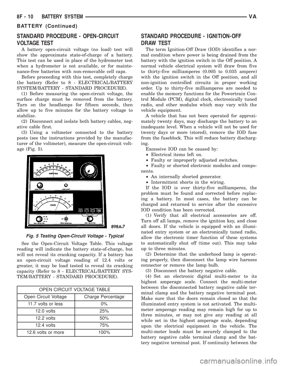
age (Fig. 5).
See the Open-Circuit Voltage Table. This voltage
reading will indicate the battery state-of-charge, but
will not reveal its cranking capacity. If a battery has
an open-circuit voltage reading of 12.4 volts or
greater, it may be load tested to reveal its cranking
capacity (Refer to 8 - ELECTRICAL/BATTERY SYS-
TEM/BATTERY - STANDARD PROCEDURE).
OPEN CIRCUIT VOLTAGE TABLE
Open Circuit Voltage Charge Percentage
11.7 volts or less 0%
12.0 volts 25%
12.2 volts 50%
12.4 volts 75%
12.6 volts or more 100%
STANDARD PROCEDURE - IGNITION-OFF
DRAW TEST
The term Ignition-Off Draw (IOD) identifies a nor-
mal condition where power is being drained from the
battery with the ignition switch in the Off position. A
normal vehicle electrical system will draw from five
to thirty-five milliamperes (0.005 to 0.035 ampere)
with the ignition switch in the Off position, and all
non-ignition controlled circuits in proper working
order. Up to thirty-five milliamperes are needed to
enable the memory functions for the Powertrain Con-
trol Module (PCM), digital clock, electronically tuned
radio, and other modules which may vary with the
vehicle equipment.
A vehicle that has not been operated for approxi-
mately twenty days, may discharge the battery to an
inadequate level. When a vehicle will not be used for
twenty days or more (stored), remove the IOD fuse
from the fuseblock. This will reduce battery discharg-
ing.
Excessive IOD can be caused by:
²Electrical items left on.
²Faulty or improperly adjusted switches.
²Faulty or shorted electronic modules and compo-
nents.
²An internally shorted generator.
²Intermittent shorts in the wiring.
If the IOD is over thirty-five milliamperes, the
problem must be found and corrected before replac-
ing a battery. In most cases, the battery can be
charged and returned to service after the excessive
IOD condition has been corrected.
(1) Verify that all electrical accessories are off.
Turn off all lamps, remove the ignition key, and close
all doors. If the vehicle is equipped with an illumi-
nated entry system or an electronically tuned radio,
allow the electronic timer function of these systems
to automatically shut off (time out). This may take
up to three minutes.
(2) Determine that the underhood lamp is operat-
ing properly, then disconnect the lamp wire harness
connector or remove the lamp bulb.
(3) Disconnect the battery negative cable.
(4) Set an electronic digital multi-meter to its
highest amperage scale. Connect the multi-meter
between the disconnected battery negative cable ter-
minal clamp and the battery negative terminal post.
Make sure that the doors remain closed so that the
illuminated entry system is not activated. The multi-
meter amperage reading may remain high for up to
three minutes, or may not give any reading at all
while set in the highest amperage scale, depending
upon the electrical equipment in the vehicle. The
multi-meter leads must be securely clamped to the
battery negative cable terminal clamp and the bat-
tery negative terminal post. If continuity between the
Fig. 5 Testing Open-Circuit Voltage - Typical
8F - 10 BATTERY SYSTEMVA
BATTERY (Continued)
Page 139 of 1232
battery negative terminal post and the negative cable
terminal clamp is lost during any part of the IOD
test, the electronic timer function will be activated
and all of the tests will have to be repeated.
(5) After about three minutes, the high-amperage
IOD reading on the multi-meter should become very
low or nonexistent, depending upon the electrical
equipment in the vehicle. If the amperage reading
remains high, remove and replace each fuse or circuit
breaker in the Fuse Blocks, one at a time until the
amperage reading becomes very low, or nonexistent.
Refer to the appropriate wiring information in this
service manual for complete fuseblock fuse, circuit
breaker, and circuit identification. This will isolate
each circuit and identify the circuit that is the source
of the high-amperage IOD. If the amperage reading
remains high after removing and replacing each fuse
and circuit breaker, disconnect the wire harness from
the generator. If the amperage reading now becomes
very low or nonexistent, refer to Charging System for
the proper charging system diagnosis and testing
procedures. After the high-amperage IOD has been
corrected, switch the multi-meter to progressively
lower amperage scales and, if necessary, repeat the
fuse and circuit breaker remove-and-replace process
to identify and correct all sources of excessive IOD. It
is now safe to select the lowest milliampere scale of
the multi-meter to check the low-amperage IOD.
CAUTION: Do not open any doors, or turn on any
electrical accessories with the lowest milliampere
scale selected, or the multi-meter may be damaged.
(6) Observe the multi-meter reading. The low-am-
perage IOD should not exceed thirty-five milliam-
peres (0.035 ampere). If the current draw exceeds
thirty-five milliamperes, isolate each circuit using the
fuse and circuit breaker remove-and-replace process
in Step 5. The multi-meter reading will drop to
within the acceptable limit when the source of the
excessive current draw is disconnected. Repair this
circuit as required; whether a wiring short, incorrect
switch adjustment, or a component failure is at fault.
STANDARD PROCEDURE - USING MICRO 420
BATTERY TESTER
Always use the Micro 420 Instruction Manual that
was supplied with the tester as a reference. If the
Instruction Manual is not available the following pro-
cedure can be used:
WARNING: ALWAYS WEAR APPROPRIATE EYE
PROTECTION AND USE EXTREME CAUTION WHEN
WORKING WITH BATTERIES.
BATTERY TESTING
(1) If testing the battery OUT-OF-VEHICLE, clean
the battery terminals with a wire brush before test-
ing. If the battery is equipped with side post termi-
nals, install and tighten the supplied lead terminal
stud adapters. Do not use steel bolts. Failure to prop-
erly install the stud adapters, or using stud adapters
that are dirty or worn-out may result in false test
readings.
(2) If testing the battery IN-THE-VEHICLE, make
certain all of the vehicle accessory loads are OFF,
including the ignition.The preferred test position
is at the battery terminal. If the battery is not
accessible, you may test using both the positive and
negative jumper posts. Select TESTING AT JUMPER
POST when connecting to that location.
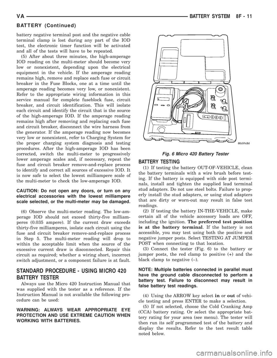
(3) Connect the tester (Fig. 6) to the battery or
jumper posts, the red clamp to positive (+) and the
black clamp to negative (±).
NOTE: Multiple batteries connected in parallel must
have the ground cable disconnected to perform a
battery test. Failure to disconnect may result in
false battery test readings.
(4) Using the ARROW key selectinoroutof vehi-
cle testing and press ENTER to make a selection.
(5) If not selected, choose the Cold Cranking Amp
(CCA) battery rating. Or select the appropriate bat-
tery rating for your area (see menu). The tester will
then run its self programmed test of the battery and
display the results. Refer to the test result table
noted below.
Fig. 6 Micro 420 Battery Tester
VABATTERY SYSTEM 8F - 11
BATTERY (Continued)