2005 MERCEDES-BENZ SPRINTER key
[x] Cancel search: keyPage 191 of 1232
OPERATION
The multi-function indicator has several display
capabilities including odometer, trip odometer, clock,
engine oil level data, gear selector indicator
(PRNDL), certain diagnostic information and, on
vehicles so equipped, an optional Active Service SYS-
Tem (ASSYST) engine oil maintenance indicator and
an optional outside ambient temperature indicator.
The multi-function indicator is completely controlled
by the instrument cluster logic circuit, and that logic
will allow this indication to be viewed whenever the
multi-function indicator Liquid Crystal Display
(LCD) is activated. Therefore, the indicator remains
functional regardless of the ignition switch position.
With the ignition switch in the Off or Accessory posi-
tions and the key removed from the ignition lock cyl-
inder, the display is activated when the park lamps
are turned On or, for about thirty seconds after any
one of the multi-function indicator switch push but-
tons is depressed. Otherwise, the display unit is
active for about thirty seconds after the key is
inserted into the ignition lock cylinder, and inactive
about thirty seconds after the key is removed from
the ignition lock cylinder.
The multi-function indicator ªmiº (miles) or
ªkmº(kilometers) switch push button is used to con-
trol the odometer/trip odometer display modes. The
multi-function indicator clock switch push button is
used to control the clock/outside temperature display
modes. The multi-function indicator ª+º (plus) and
ª2º (minus) switch push buttons are used to adjust
the cluster general illumination dimming level, the
clock, and other cluster settings. See the owner's
manual in the vehicle glove box for more information
on the features, use, operation and setting proce-
dures for the various standard and optional multi-
function indicator displays.
Proper testing of the multi-function indicator LCD
unit, the CAN data bus and the electronic data bus
message inputs to the instrument cluster that control
some of the multi-function indicator functions
requires the use of a DRBIIItscan tool. Refer to the
appropriate diagnostic information. Additional details
for the odometer/trip odometer, the clock, the gear
selector indicator, the ambient temperature indicator
and the ASSYST warning and reminder functions of
the multi-function indicator may be found elsewhere
in this service information.
ODOMETER
DESCRIPTION
An odometer and trip odometer are standard
equipment in all instrument clusters. The odometer
and trip odometer values are displayed on the leftside of the multi-function indicator Liquid Crystal
Display (LCD). The LCD is soldered onto the cluster
electronic circuit board and is visible through a win-
dow with a clear lens located near the lower edge of
the instrument cluster, directly below the speedome-
ter. However, the odometer and trip odometer infor-
mation are not displayed simultaneously. The ªmiº
(miles) or ªkmº (kilometers) switch on the instrument
cluster circuit board toggles the display between
odometer and trip odometer modes by depressing the
switch push button that extends through the lower
edge of the cluster lens, directly below the multi-
function indicator LCD.
The odometer and trip odometer information is
stored in the instrument cluster memory. This infor-
mation can be increased when the proper inputs are
provided to the instrument cluster, but the informa-
tion cannot be decreased. The odometer can display
values up to 999,999 kilometers (999,999 miles). The
odometer latches at these values, and will not roll
over to zero. The trip odometer can display values up
to 999.9 kilometers (999.9 miles) before it rolls over
to zero. The odometer display does not have a deci-
mal point and will not show values less than a full
unit (kilometer or mile), while the trip odometer dis-
play does have a decimal point and will show tenths
of a unit (kilometer or mile). The unit of measure
(kilometers or miles) for the odometer and trip odom-
eter display is imprinted on the cluster overlay below
the left end of the LCD. The unit of measure for the
instrument cluster odometer/trip odometer is selected
at the time that it is manufactured, and cannot be
changed.
The indications of the odometer/trip odometer are
not visible when the LCD is not illuminated. When
illuminated the indications appear as dark charac-
ters silhouetted against an amber field. When the
exterior lighting is turned Off, the display is illumi-
nated at maximum brightness. When the exterior
lighting is turned On the display illumination level
can be adjusted in concert with the cluster general
illumination lighting using the plus and minus multi-
function indicator push buttons. The odometer has a
ªRental Carº mode, which will activate the multi-
function indicator LCD and illuminate the odometer
information for about thirty seconds after one of the
multi-function indicator push buttons is momentarily
depressed, or after the key is inserted into the igni-
tion switch lock cylinder with the ignition switch in
the Off position.
The odometer/trip odometer and the miles/kilome-
ters switch, and the miles/kilometers switch push
button are serviced as a unit with the instrument
cluster.
VAINSTRUMENT CLUSTER 8J - 21
MULTI-FUNCTION INDICATOR (Continued)
Page 233 of 1232
POWER SYSTEMS
TABLE OF CONTENTS
page page
POWER LOCKS............................ 1
POWER MIRRORS......................... 3POWER WINDOWS......................... 5
POWER LOCKS
TABLE OF CONTENTS
page page
POWER LOCKS
DESCRIPTION..........................1
DOOR LOCK MOTOR
REMOVAL.............................1
INSTALLATION..........................1
REMOTE KEYLESS ENTRY TRANSMITTER
DESCRIPTION..........................2MASTER LOCK SWITCH
DESCRIPTION..........................2
DIAGNOSIS AND TESTING - MASTER LOCK
SWITCH.............................2
REMOVAL.............................2
INSTALLATION..........................2
POWER LOCKS
DESCRIPTION
CENTRAL LOCKING
The central locking system locks all vehicle doors if
any door is locked from the inside or mechanically
locked with the key from the outside. the master door
lock switch on the instrument panel enables the
operator to lock/unlock all doors.
REMOTE KEYLESS ENTRY
The SKREEM is a combination of the Remote Key-
less Entry (RKE) module and the Sentry Key Immo-
bilizer (SKIM) module. It is located behind the
instrument cluster and has an antenna that mounts
to the A-pillar.
AUTO DOOR LOCKS
Whenever the engine is started, the CTM receivers
a message to lock all doors except the drivers door.
This is accomplished through a relay. The relay is
controlled by the Instrument Cluster which receives
a command from the ECM.
ACCIDENT RESPONSE
The CTM is hardwired to the Airbag Control Mod-
ule through the Enhanced Accident Report Driver cir-
cuit. Anytime the vehicles airbags are deployed, the
CTM will unlock all doors and a ªcrashº DTC will be
stored in memory. The door locks will be inoperative
until that code is cleared.
DOOR LOCK MOTOR
REMOVAL
(1) Disconnect and isolate the battery negative
cable.
(2) Remove the door trim panel.
(3) Remove the door lock.
(4) Remove the door lock motor from the door lock.
INSTALLATION
(1) Install the door lock motor to the door lock.
(2) Install the door lock.
(3) Install the door trim panel.
(4) Connect the battery negative cable.
VAPOWER SYSTEMS 8N - 1
Page 234 of 1232
REMOTE KEYLESS ENTRY
TRANSMITTER
DESCRIPTION
Pressing the unlock button on the transmitter will
unlock the drivers door, pressing it a second time
within 2.5 seconds will unlock all other doors. The
transmitter has a range of 10 meters. A key is inte-
gral to the transmitter.
When a transmitter is lost, it is necessary to dis-
able the affected transmitter so that it can no longer
be used to operate the vehicle. It will then be neces-
sary to program a new transmitter to the vehicle.
MASTER LOCK SWITCH
DESCRIPTION
The master lock switch is a momentary contact
switch. Pressing the once in the up direction unlocks
the driver door. Pressing it again in the same direc-
tion unlocks all doors. Pressing the button in the
down direction locks all doors.
DIAGNOSIS AND TESTING - MASTER LOCK
SWITCH
(1) Disconnect and isolate the battery negative
cable.
(2) Remove the switch to be tested.
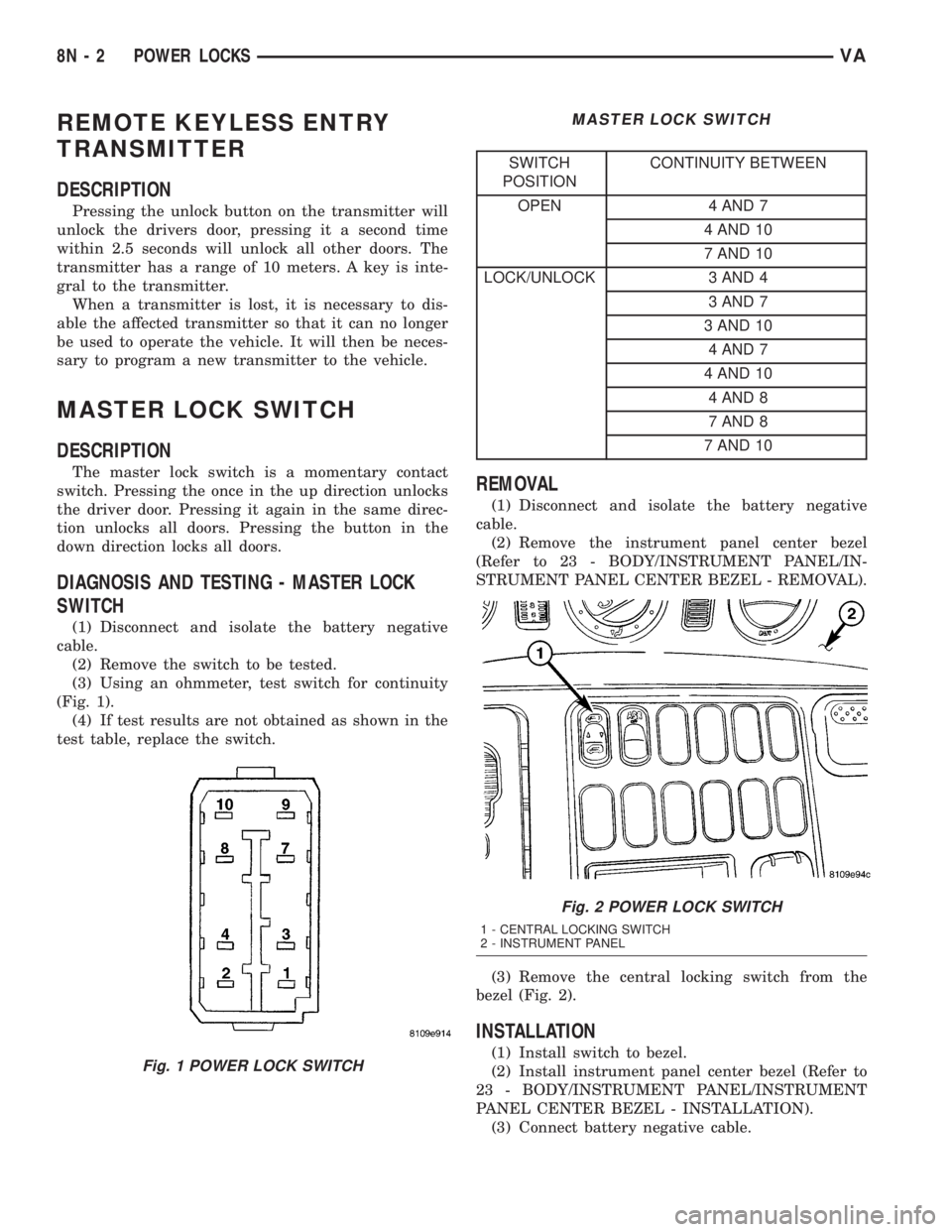
(3) Using an ohmmeter, test switch for continuity
(Fig. 1).
(4) If test results are not obtained as shown in the
test table, replace the switch.
MASTER LOCK SWITCH
SWITCH
POSITIONCONTINUITY BETWEEN
OPEN 4 AND 7
4 AND 10
7 AND 10
LOCK/UNLOCK 3 AND 4
3 AND 7
3 AND 10
4 AND 7
4 AND 10
4 AND 8
7 AND 8
7 AND 10
REMOVAL
(1) Disconnect and isolate the battery negative
cable.
(2) Remove the instrument panel center bezel
(Refer to 23 - BODY/INSTRUMENT PANEL/IN-
STRUMENT PANEL CENTER BEZEL - REMOVAL).
(3) Remove the central locking switch from the
bezel (Fig. 2).
INSTALLATION
(1) Install switch to bezel.
(2) Install instrument panel center bezel (Refer to
23 - BODY/INSTRUMENT PANEL/INSTRUMENT
PANEL CENTER BEZEL - INSTALLATION).
(3) Connect battery negative cable.Fig. 1 POWER LOCK SWITCH
Fig. 2 POWER LOCK SWITCH
1 - CENTRAL LOCKING SWITCH
2 - INSTRUMENT PANEL
8N - 2 POWER LOCKSVA
Page 251 of 1232
vide access to the case mounting screws. The lower
side of the rotor hub also serves as an integral
molded plastic turn signal cancel cam.
A single connector receptacle on the upper surface
of the rotor has pigtail wires that connect to the horn
switch and the driver airbag on the steering wheel,
while a single connector receptacle on the lower sur-
face of the case has pigtail wires that connect the
clockspring to the vehicle wire harness on the steer-
ing column. Within the plastic case and wound
around the rotor spool is a long ribbon-like tape that
consists of several thin copper wire leads sandwiched
between two thin plastic membranes. The outer end
of the tape terminates at the connector receptacle
that faces the steering column, while the inner end of
the tape terminates at the connector receptacle on
the hub of the clockspring rotor that faces the steer-
ing wheel.
Service replacement clocksprings are shipped pre-
centered and with the mounting screws backed out
from the case far enough to engage the access holes
in the upper surface of the rotor. The mounting
screws secure the centered clockspring rotor to the
clockspring case during shipment, but allow free
rotation of the rotor once the clockspring is properly
installed on the steering column. (Refer to 8 - ELEC-
TRICAL/RESTRAINTS/CLOCKSPRING - STAN-
DARD PROCEDURE - CLOCKSPRING
CENTERING).
The clockspring cannot be repaired. If the clock-
spring is faulty, damaged, or if the driver airbag has
been deployed, the clockspring must be replaced.
OPERATION
The clockspring is a mechanical electrical circuit
component that is used to provide continuous electri-
cal continuity between the fixed vehicle wire harness
and the electrical components mounted on or in the
rotating steering wheel. On this model the rotating
electrical components include the driver airbag and
the horn switch. The clockspring case is positioned
and secured to the multi-function switch housing
near the top of the steering column. The connector
receptacle on the underside of the fixed clockspring
case connects the clockspring to the vehicle electrical
system through two take outs with connectors from
the vehicle wire harness.
The clockspring rotor is movable and is keyed by
integral molded ribs on the inner circumference of
the rotor hub to the splines on the external circum-
ference of the upper steering column shaft. The two
integral lobes of the turn signal cancel cam formation
on the lower surface of the clockspring rotor hub con-
tact the turn signal cancel actuator of the multi-func-
tion switch to provide automatic turn signal
cancellation. The yellow sleeved pigtail wire on theupper surface of the clockspring rotor connects the
clockspring to the driver airbag, while two single pig-
tail wires connect to the feed and ground terminals of
the horn switch located within the hub cavity of the
steering wheel.
Like the clockspring in a timepiece, the clockspring
tape has travel limits and can be damaged by being
wound too tightly during full stop-to-stop steering
wheel rotation. To prevent this from occurring, the
clockspring is centered when it is installed on the
steering column. Centering the clockspring indexes
the clockspring tape to the movable steering compo-
nents so that the tape can operate within its
designed travel limits. However, if the clockspring is
removed from the steering column or if the steering
shaft is disconnected from the steering gear, the
clockspring spool can change position relative to the
movable steering components. The clockspring must
be re-centered following completion of this service or
the tape may be damaged.
Service replacement clocksprings are shipped pre-
centered and with the mounting screws backed out
from the case far enough to engage the access holes
in the upper surface of the rotor. The mounting
screws secure the centered clockspring rotor to the
clockspring case during shipment, but allow free
rotation of the rotor once the clockspring is properly
installed on the steering column. The clockspring
mounting screws should not be tightened into the
clockspring case until the clockspring has been
installed on the steering column. If the screws are
tightened into or removed from the case before the
clockspring is installed on a steering column, the
clockspring centering procedure must be performed.
(Refer to 8 - ELECTRICAL/RESTRAINTS/CLOCK-
SPRING - STANDARD PROCEDURE - CLOCK-
SPRING CENTERING).
STANDARD PROCEDURE - CLOCKSPRING
CENTERING
The clockspring is designed to wind and unwind
when the steering wheel is rotated, but is only
designed to rotate the same number of turns (about
six to seven complete rotations) as the steering wheel
can be turned from stop to stop. Centering the clock-
spring indexes the clockspring tape to other steering
components so that it can operate within its designed
travel limits. The rotor of a centered clockspring can
be rotated three to three and one-half turns in either
direction from the centered position, without damag-
ing the clockspring tape.
However, if the clockspring is removed for service
or if the steering column is disconnected from the
steering gear, the clockspring tape can change posi-
tion relative to the other steering components. The
clockspring must then be re-centered following com-
VARESTRAINTS 8O - 13
CLOCKSPRING (Continued)
Page 254 of 1232
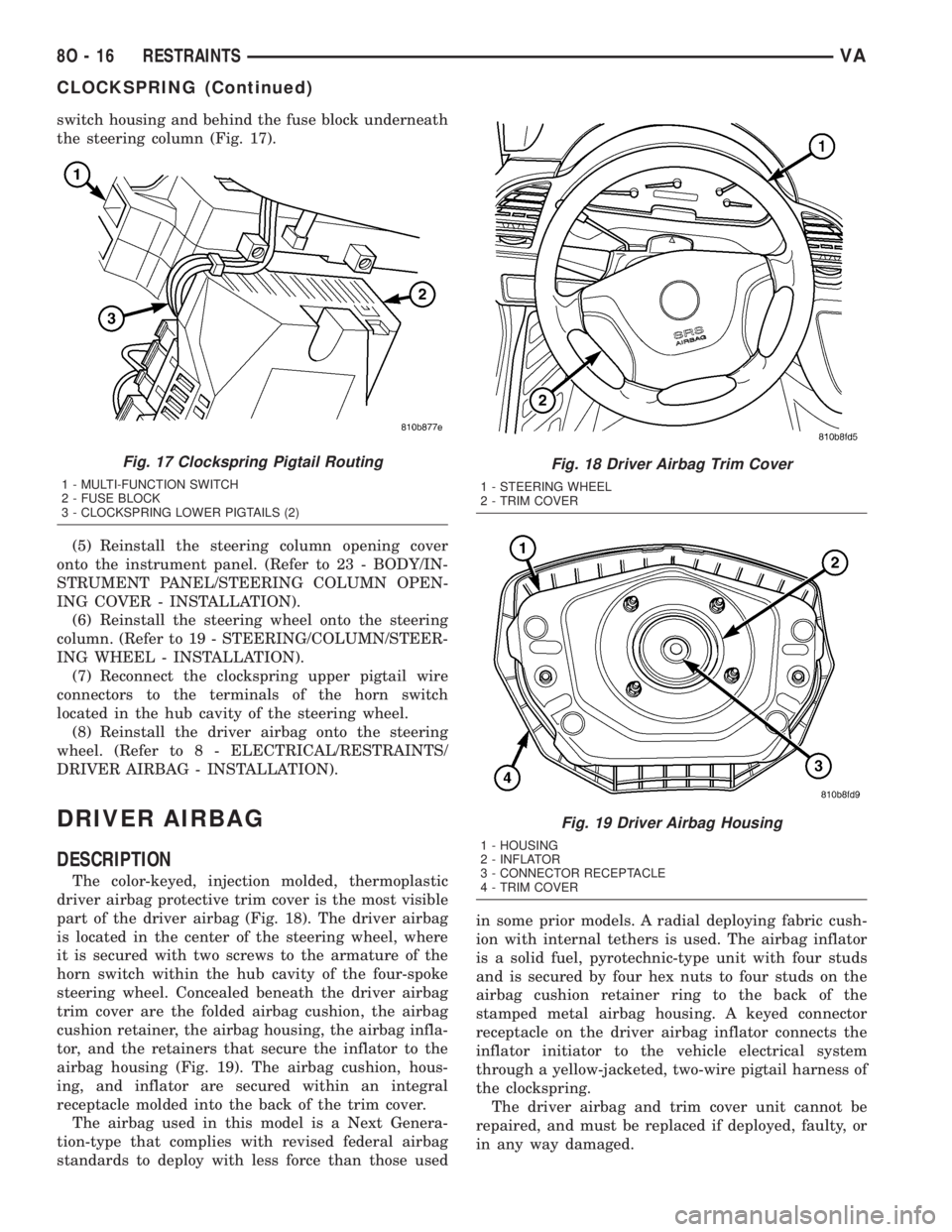
switch housing and behind the fuse block underneath
the steering column (Fig. 17).
(5) Reinstall the steering column opening cover
onto the instrument panel. (Refer to 23 - BODY/IN-
STRUMENT PANEL/STEERING COLUMN OPEN-
ING COVER - INSTALLATION).
(6) Reinstall the steering wheel onto the steering
column. (Refer to 19 - STEERING/COLUMN/STEER-
ING WHEEL - INSTALLATION).
(7) Reconnect the clockspring upper pigtail wire
connectors to the terminals of the horn switch
located in the hub cavity of the steering wheel.
(8) Reinstall the driver airbag onto the steering
wheel. (Refer to 8 - ELECTRICAL/RESTRAINTS/
DRIVER AIRBAG - INSTALLATION).
DRIVER AIRBAG
DESCRIPTION
The color-keyed, injection molded, thermoplastic
driver airbag protective trim cover is the most visible
part of the driver airbag (Fig. 18). The driver airbag
is located in the center of the steering wheel, where
it is secured with two screws to the armature of the
horn switch within the hub cavity of the four-spoke
steering wheel. Concealed beneath the driver airbag
trim cover are the folded airbag cushion, the airbag
cushion retainer, the airbag housing, the airbag infla-
tor, and the retainers that secure the inflator to the
airbag housing (Fig. 19). The airbag cushion, hous-
ing, and inflator are secured within an integral
receptacle molded into the back of the trim cover.
The airbag used in this model is a Next Genera-
tion-type that complies with revised federal airbag
standards to deploy with less force than those usedin some prior models. A radial deploying fabric cush-
ion with internal tethers is used. The airbag inflator
is a solid fuel, pyrotechnic-type unit with four studs
and is secured by four hex nuts to four studs on the
airbag cushion retainer ring to the back of the
stamped metal airbag housing. A keyed connector
receptacle on the driver airbag inflator connects the
inflator initiator to the vehicle electrical system
through a yellow-jacketed, two-wire pigtail harness of
the clockspring.
The driver airbag and trim cover unit cannot be
repaired, and must be replaced if deployed, faulty, or
in any way damaged.
Fig. 17 Clockspring Pigtail Routing
1 - MULTI-FUNCTION SWITCH
2 - FUSE BLOCK
3 - CLOCKSPRING LOWER PIGTAILS (2)
Fig. 18 Driver Airbag Trim Cover
1 - STEERING WHEEL
2 - TRIM COVER
Fig. 19 Driver Airbag Housing
1 - HOUSING
2 - INFLATOR
3 - CONNECTOR RECEPTACLE
4 - TRIM COVER
8O - 16 RESTRAINTSVA
CLOCKSPRING (Continued)
Page 270 of 1232
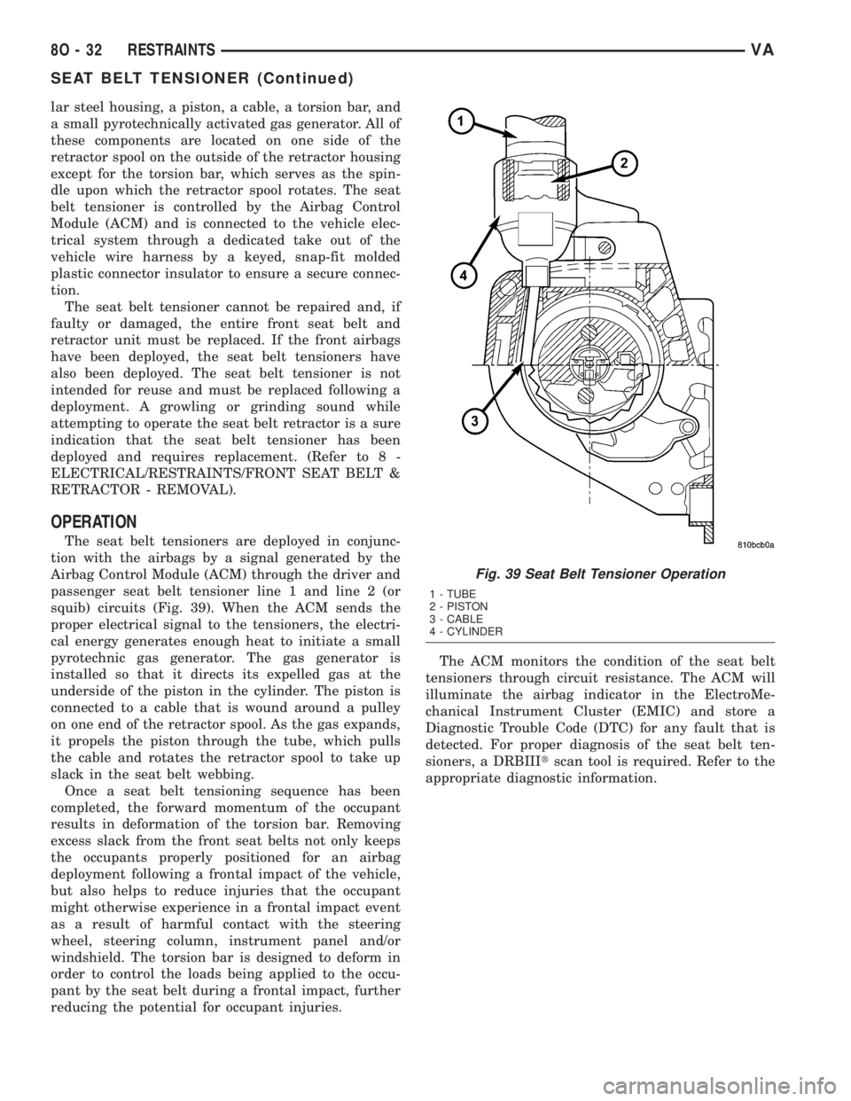
lar steel housing, a piston, a cable, a torsion bar, and
a small pyrotechnically activated gas generator. All of
these components are located on one side of the
retractor spool on the outside of the retractor housing
except for the torsion bar, which serves as the spin-
dle upon which the retractor spool rotates. The seat
belt tensioner is controlled by the Airbag Control
Module (ACM) and is connected to the vehicle elec-
trical system through a dedicated take out of the
vehicle wire harness by a keyed, snap-fit molded
plastic connector insulator to ensure a secure connec-
tion.
The seat belt tensioner cannot be repaired and, if
faulty or damaged, the entire front seat belt and
retractor unit must be replaced. If the front airbags
have been deployed, the seat belt tensioners have
also been deployed. The seat belt tensioner is not
intended for reuse and must be replaced following a
deployment. A growling or grinding sound while
attempting to operate the seat belt retractor is a sure
indication that the seat belt tensioner has been
deployed and requires replacement. (Refer to 8 -
ELECTRICAL/RESTRAINTS/FRONT SEAT BELT &
RETRACTOR - REMOVAL).
OPERATION
The seat belt tensioners are deployed in conjunc-
tion with the airbags by a signal generated by the
Airbag Control Module (ACM) through the driver and
passenger seat belt tensioner line 1 and line 2 (or
squib) circuits (Fig. 39). When the ACM sends the
proper electrical signal to the tensioners, the electri-
cal energy generates enough heat to initiate a small
pyrotechnic gas generator. The gas generator is
installed so that it directs its expelled gas at the
underside of the piston in the cylinder. The piston is
connected to a cable that is wound around a pulley
on one end of the retractor spool. As the gas expands,
it propels the piston through the tube, which pulls
the cable and rotates the retractor spool to take up
slack in the seat belt webbing.
Once a seat belt tensioning sequence has been
completed, the forward momentum of the occupant
results in deformation of the torsion bar. Removing
excess slack from the front seat belts not only keeps
the occupants properly positioned for an airbag
deployment following a frontal impact of the vehicle,
but also helps to reduce injuries that the occupant
might otherwise experience in a frontal impact event
as a result of harmful contact with the steering
wheel, steering column, instrument panel and/or
windshield. The torsion bar is designed to deform in
order to control the loads being applied to the occu-
pant by the seat belt during a frontal impact, further
reducing the potential for occupant injuries.The ACM monitors the condition of the seat belt
tensioners through circuit resistance. The ACM will
illuminate the airbag indicator in the ElectroMe-
chanical Instrument Cluster (EMIC) and store a
Diagnostic Trouble Code (DTC) for any fault that is
detected. For proper diagnosis of the seat belt ten-
sioners, a DRBIIItscan tool is required. Refer to the
appropriate diagnostic information.
Fig. 39 Seat Belt Tensioner Operation
1 - TUBE
2 - PISTON
3 - CABLE
4 - CYLINDER
8O - 32 RESTRAINTSVA
SEAT BELT TENSIONER (Continued)
Page 277 of 1232

VEHICLE THEFT SECURITY
TABLE OF CONTENTS
page page
VEHICLE THEFT SECURITY
DESCRIPTION..........................1
OPERATION............................1
DIAGNOSIS AND TESTING - VEHICLE THEFT
SECURITY............................1
INTRUSION SENSOR
REMOVAL.............................2
INSTALLATION..........................2
SECURITY SYSTEM MODULE
REMOVAL.............................2
INSTALLATION..........................2SENTRY KEY REMOTE ENTRY MODULE
DESCRIPTION..........................2
OPERATION............................3
REMOVAL.............................3
INSTALLATION..........................4
SIREN
REMOVAL.............................4
INSTALLATION..........................4
TRANSPONDER KEY
DESCRIPTION..........................5
OPERATION............................5
VEHICLE THEFT SECURITY
DESCRIPTION
An anti-theft alarm with battery powered horn is
available as an option and includes interior monitor-
ing, anti-tow away protection and rear window mon-
itoring based on the heater wires. The alarm is
automatically activated when the central locking sys-
tem is operated.
The alarm will sound when any of the following
occur:
²A door is opened
²A door is unlocked from inside the vehicle
²The hood is opened
²The vehicle is raised at the front or rear
²The trailer wire harness is disconnected
²Movements inside the vehicle
²The central locking is unlocked by a key at any
other door than the driver's door
The alarm is functional about 30 seconds after the
vehicle is locked using the RKE transmitter or the
key in the driver's door. Activation is indicated by the
indicator lights flashing three times and the warning
lamp flashing in the switch. If persons or animals
remain in the locked vehicle, the operator should
switch off the interior monitor to avoid a false alarm.
OPERATION
The anti-theft alarm is activated/deactivated by
locking/unlocking the vehicle with the remote trans-
mitter or with the key at the driver's door. The key
must be held in the locking position for more than
two seconds. Activation is indicated by the turn sig-
nal lights flashing once. Unlocking the vehicle at one
of the other doors will trigger an alarm.The interior monitoring system included in the
anti-theft alarm is based on ultrasonics and triggers
an alarm if an object intrudes the interior of the
vehicle or if any movement is detected inside the
vehicle. For proper and effective protection, all win-
dows and the sunroof must be closed.
To switch off the interior monitoring system and /
or the anti-tow away protection, a switch with LED
indicator light is provided in the switch panel. An
alarm button enables the operator to trigger an
alarm manually and to lock all doors if they are
closed. Triggering an alarm makes the horn sound
and the turn signals flash until the alarm is switched
off.
The anti-theft alarm control unit includes a gradi-
ent indicator as anti-tow away protection. The gradi-
ent indicator triggers an audible and visual alarm if
the vehicle is lifted (to tow away or to remove the
wheels). The alarm remains effective even if the bat-
tery is disconnected as the horn is powered by its
own battery. The interior monitoring system should
be switched off if people and/or animals are left in
the vehicle.
DIAGNOSIS AND TESTING - VEHICLE THEFT
SECURITY
Any diagnosis of the Vehicle Theft Security
system should begin with the use of the DRB
IIItdiagnostic tool. For information on the use
of the DRB IIIt, refer to the appropriate Diag-
nostic Service Manual.
VAVEHICLE THEFT SECURITY 8Q - 1
Page 278 of 1232
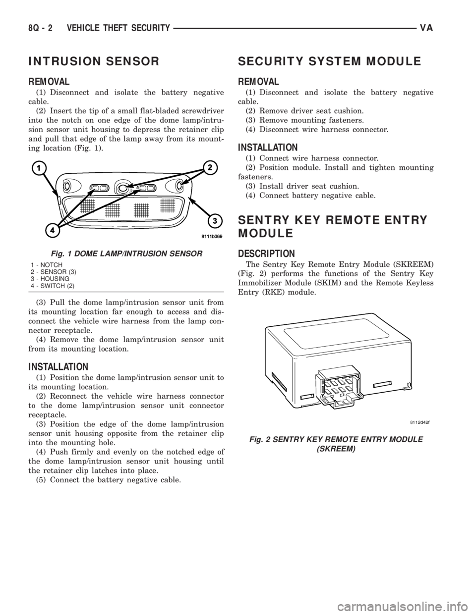
INTRUSION SENSOR
REMOVAL
(1) Disconnect and isolate the battery negative
cable.
(2) Insert the tip of a small flat-bladed screwdriver
into the notch on one edge of the dome lamp/intru-
sion sensor unit housing to depress the retainer clip
and pull that edge of the lamp away from its mount-
ing location (Fig. 1).
(3) Pull the dome lamp/intrusion sensor unit from
its mounting location far enough to access and dis-
connect the vehicle wire harness from the lamp con-
nector receptacle.
(4) Remove the dome lamp/intrusion sensor unit
from its mounting location.
INSTALLATION
(1) Position the dome lamp/intrusion sensor unit to
its mounting location.
(2) Reconnect the vehicle wire harness connector
to the dome lamp/intrusion sensor unit connector
receptacle.
(3) Position the edge of the dome lamp/intrusion
sensor unit housing opposite from the retainer clip
into the mounting hole.
(4) Push firmly and evenly on the notched edge of
the dome lamp/intrusion sensor unit housing until
the retainer clip latches into place.
(5) Connect the battery negative cable.
SECURITY SYSTEM MODULE
REMOVAL
(1) Disconnect and isolate the battery negative
cable.
(2) Remove driver seat cushion.
(3) Remove mounting fasteners.
(4) Disconnect wire harness connector.
INSTALLATION
(1) Connect wire harness connector.
(2) Position module. Install and tighten mounting
fasteners.
(3) Install driver seat cushion.
(4) Connect battery negative cable.
SENTRY KEY REMOTE ENTRY
MODULE
DESCRIPTION
The Sentry Key Remote Entry Module (SKREEM)
(Fig. 2) performs the functions of the Sentry Key
Immobilizer Module (SKIM) and the Remote Keyless
Entry (RKE) module.
Fig. 1 DOME LAMP/INTRUSION SENSOR
1 - NOTCH
2 - SENSOR (3)
3 - HOUSING
4 - SWITCH (2)
Fig. 2 SENTRY KEY REMOTE ENTRY MODULE
(SKREEM)
8Q - 2 VEHICLE THEFT SECURITYVA