2005 MERCEDES-BENZ SPRINTER key
[x] Cancel search: keyPage 682 of 1232
READING LAMP CONNECTOR
CAV CIRCUIT FUNCTION
1 16BR GROUND
2 16RD/YL MAP/READING LAMP SWITCH OUTPUT
RECIRCULATED AIR SOLENOID VALVE
CAV CIRCUIT FUNCTION
1 16RD RECIRCULATED AIR SOLENOID VALVE CONTROL
2 16BK GROUND
REFRIGERANT PRESSURE SENSOR
CAV CIRCUIT FUNCTION
1 18BR/BL SENSOR GROUND
2 20BR/RD REFRIGERANT PRESSURE SENSOR FEEDBACK
3 20RD/BL 5 VOLT SUPPLY
REMOTE KEYLESS ENTRY ANTENNA
CAV CIRCUIT FUNCTION
1 20BR RKE ANTENNA
3 - GROUND
ROOF FAN MOTOR
CAV CIRCUIT FUNCTION
1 16WT SUPPLY VOLTAGE
2 16BK RETURN
8W - 80 - 56 8W-80 CONNECTOR PIN-OUTSVA
Page 684 of 1232
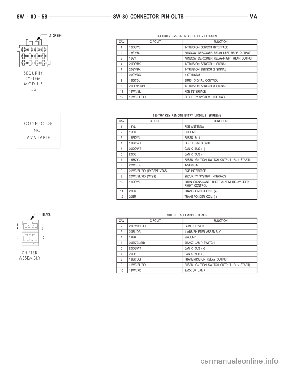
SECURITY SYSTEM MODULE C2 - LT.GREEN
CAV CIRCUIT FUNCTION
1 16DG/YL INTRUSION SENSOR INTERFACE
2 16GY/BL WINDOW DEFOGGER RELAY-LEFT REAR OUTPUT
3 16GY WINDOW DEFOGGER RELAY-RIGHT REAR OUTPUT
4 20DG/BK INTRUSION SENSOR 1 SIGNAL
7 20GY/BK INTRUSION SENSOR 2 SIGNAL
8 20GY/DG K-CTM/SSM
9 18BK/BL SIREN SIGNAL CONTROL
10 20DG/WT/BL INTRUSION SENSOR 3 SIGNAL
11 16WT/BL RKE INTERFACE
12 16WT/BL/RD SECURITY SYSTEM INTERFACE
SENTRY KEY REMOTE ENTRY MODULE (SKREEM)
CAV CIRCUIT FUNCTION
1 18YL RKE ANTENNA
2 16BR GROUND
3 16RD/YL FUSED B(+)
4 16BK/WT LEFT TURN SIGNAL
5 20DG/WT CAN C BUS (+)
6 20DG CAN C BUS (-)
7 16BK/YL FUSED IGNITION SWITCH OUTPUT (RUN-START)
8 20WT/DG K-SKREEM
9 20WT/BL/RD (EXCEPT VTSS) RKE INTERFACE
9 20WT/BL/RD (VTSS) SECURITY SYSTEM INTERFACE
10 18DG/YL TURN SIGNAL/ANTI-THEFT ALARM RELAY-LEFT/
RIGHT CONTROL
11 20BR TRANSPONDER COIL (+)
12 20BR TRANSPONDER COIL (-)
SHIFTER ASSEMBLY - BLACK
CAV CIRCUIT FUNCTION
2 20GY/DG/RD LAMP DRIVER
3 20BL/DG K-ABS/SHIFTER ASSEMBLY
4 18BR GROUND
5 20BK/BL/RD BRAKE LAMP SWITCH
6 20DG/WT CAN C BUS (+)
7 20DG CAN C BUS (-)
8 18BK/DG TRANSMISSION RELAY OUTPUT
9 16WT/BL/RD FUSED IGNITION SWITCH OUTPUT (RUN-START)
10 16WT/RD BACK-UP LAMP
8W - 80 - 58 8W-80 CONNECTOR PIN-OUTSVA
Page 702 of 1232
CONNECTOR NAME/
NUMBERCOLOR LOCATION FIG.
Refrigerant Pressure Sensor Engine Compartment-Left Front 3,4
Relay Block Under Driver Seat 18
Remote Keyless Entry
AntennaNear Remote Keyless Entry
ModuleN/S
Remote Keyless Entry
ModuleInstrument Panel N/S
Roof Fan Motor In Headliner N/S
S165 Middle Of Vehicle N/S
Seat Belt Switch Driver Seat Belt Lock N/S
Seat Belt Tensioner-Driver Driver Seat-Back 16
Seat Belt Tensioner-
PassengerPassenger Seat-Back 16
Security System Module C1 Instrument Panel N/S
Security System Module C2 Instrument Panel N/S
Sentry Key Remote Entry
Module (SKREEM)Instrument Panel N/S
Shifter Assembly Center Console 12
Side Marker Lamp Connector Engine Compartment N/S
Siren Engine Compartment-Left 1
Speaker-Left Front Door
Assembly C1Engine Compartment-Left N/S
Speaker-Left Front Door
Assembly C2In Left Front Door N/S
Speaker-Left Rear Rear Of Vehicle On Left Side N/S
Speaker-Right Front Door In Right Front Door N/S
Speaker-Right Rear Rear Of Vehicle On Right Side N/S
Speed Control Switch Steering Wheel Controls 10
Starter Motor On Engine N/S
Starter Motor Relay
(Fuse/Relay Block)In Fuse/Relay Block N/S
Tail Lamp Assembly-Left Rear Of Vehicle On Left Side N/S
Tail Lamp Assembly-Right Rear Of Vehicle On Right Side N/S
TCS Switch (ASR) Center Of Instrument Panel N/S
Temperature Switch Instrument Panel N/S
Time Delay Relay Under Driver Seat N/S
Towing/Interior Motion Sensor Instrument Panel N/S
Trailer Tow Connector Under Rear Of Vehicle N/S
Trailer Tow Control Module
C1Rear Of Vehicle N/S
Trailer Tow Control Module
C2Rear Of Vehicle N/S
Transmission Control Module
C1Engine Compartment N/S
8W - 91 - 8 8W-91 CONNECTOR/GROUND/SPLICE LOCATIONVA
CONNECTOR/GROUND/SPLICE LOCATION (Continued)
Page 705 of 1232
SPLICE
NUMBERLOCATION FIG.
S207 Near Time Delay Relay N/S
S208 Near Time Delay Relay N/S
S210 Near Radio N/S
S211 Near Heater Timer-Auxiliary N/S
S212 Near Security System Module N/S
S213 Near Security System Module N/S
S214 Near Security System Module N/S
S215 Instrument Panel 18
S216 Instrument Panel N/S
S217 Near Engine Control Module N/S
S218 Instrument Panel N/S
S219 Under Drivers Seat N/S
S220 Near Central Timer Module N/S
S221 Near Data Link Connector N/S
S222 Near Security System Module N/S
S223 Instrument Panel N/S
S224 Instrument Panel 18
S225 Instrument Panel N/S
S226 Near Turn Signal/Anti-Theft Alarm Relay-Left N/S
S227 Near Sentry Key Remote Entry Module N/S
S228 Instrument Panel N/S
S229 Near C202 N/S
S250 Near Turn Signal/Anti-Theft Alarm Relay-Left N/S
S251 Near Trailer Tow Control Module N/S
S252 Near Trailer Tow Control Module N/S
S253 Instrument Panel 12
S254 Near Interior Lamp No.5 N/S
S255 Near Control Timer Module N/S
S256 Near A/C Roof-Switch N/S
S257 Near Data Link Connector N/S
S258 Near Transmission Control Module N/S
S259 Under Drivers Seat 19
S260 Under Drivers Seat 19
S261 Near Data Link Connector N/S
S262 Under Drivers Seat N/S
S299 Instrument Panel N/S
S300 Near Heated Seat Switch-Driver N/S
S301 Near Heated Seat Switch-Passenger N/S
S302 Under Drivers Seat N/S
S303 Near Power Window Switch-Driver N/S
S304 Near Power Window Motor-Driver N/S
VA8W-91 CONNECTOR/GROUND/SPLICE LOCATION 8W - 91 - 11
CONNECTOR/GROUND/SPLICE LOCATION (Continued)
Page 786 of 1232
NOTE: If grooves can be felt in the belt pulley/vibra-
tion damper during inspection, the pulley/damper
must be replaced.
(6) Inspect hub at belt pulley/vibration damper for
wear grooves.
(7) Replace front crankshaft seal.
INSTALLATION
NOTE: Align parallel key, fix in place with grease.
Turn to ensure the slot is aligned with parallel key
in crankshaft.
NOTE: Front crankshaft seal must be replaced
before installing the belt pulley/vibration damper.
(1) Position the belt pulley/vibration damper.
(2) Install crankshaft center bolt and washer.
Tighten bolt in two stages. M8.8 bolt to 200N´m (148
lbs. ft.) then 90É, M10.9 bolt to 325N´m (240 lbs. ft.)
then 90É.
(3) Remove the retaining lock for the crankshaft/
ring gear (Fig. 43).
NOTE: Inspect accessory drive belt for wear.
Replace as necessary.
(4) Install accessory drive belt (Refer to 7 - COOL-
ING/ACCESSORY DRIVE/DRIVE BELTS - INSTAL-
LATION).
(5) Reconnect negative battery cable.
WARNING: USE EXTREME CAUTION WHEN THE
ENGINE IS IN OPERATION. DO NOT STAND IN A
DIRECT LINE WITH THE FAN. DO NOT PUT YOUR
HANDS NEAR THE PULLEYS, BELTS OR FAN. DO
NOT WEAR LOOSE CLOTHING.
(6) Start vehicle and inspect for leaks.
VACUUM PUMP
DESCRIPTION
The vacuum pump is operated by a slotted exten-
sion attached to the vacuum pump shaft. The vac-
uum pump shaft slotted extension fits into, and is
driven by, the exhaust camshaft gear.
The vacuum pump is a constant displacement,
vane-type pump. Vacuum is generated by vanes
mounted in the pump rotor. The rotor is located in
the pump housing and is pressed onto the pump
shaft.
The vacuum pump rotating components are inter-
nally lubricated.The vacuum pump is not serviceable and must be
replaced as a unit. Do not disassemble or attempt to
repair the pump.
OPERATION
Vacuum pump output is transmitted to the Heater,
Electronic, Vacuum, Air Conditioner (HEVAC) and
speed control, systems through a supply hose. The
hose is connected to an outlet port on the pump hous-
ing and uses an in-line check valve to retain system
vacuum when vehicle is not running.
Pump output ranges from a minimum of 8.5 to 25
inches vacuum.
The pump rotor and vanes are rotated by the pump
drive gear. The drive gear is operated by the exhaust
camshaft gear.
REMOVAL
(1) Disconnect negative battery cable.
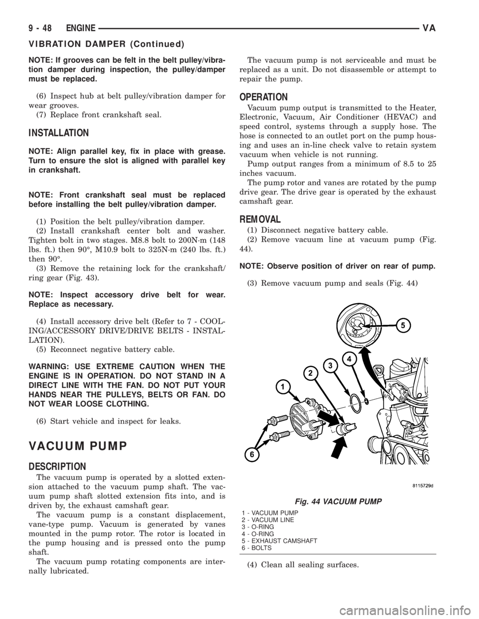
(2) Remove vacuum line at vacuum pump (Fig.
44).
NOTE: Observe position of driver on rear of pump.
(3) Remove vacuum pump and seals (Fig. 44)
(4) Clean all sealing surfaces.
Fig. 44 VACUUM PUMP
1 - VACUUM PUMP
2 - VACUUM LINE
3 - O-RING
4 - O-RING
5 - EXHAUST CAMSHAFT
6 - BOLTS
9 - 48 ENGINEVA
VIBRATION DAMPER (Continued)
Page 865 of 1232
COLUMN
TABLE OF CONTENTS
page page
COLUMN
SPECIFICATIONS - TORQUE CHART.........5
INTERMEDIATE SHAFT
REMOVAL.............................5
INSTALLATION..........................5
KEY/LOCK CYLINDER
REMOVAL.............................6INSTALLATION..........................7
STEERING WHEEL
REMOVAL.............................7
INSTALLATION..........................7
COLUMN
SPECIFICATIONS - TORQUE CHART
TORQUE SPECIFICATIONS
DESCRIPTION N´m Ft. Lbs. In. Lbs.
Steering Wheel With
Airbag To Steering Shaft80 59 Ð
Jacket Tube For Steering
Shaft To Waist Rail25 18 221
U-Joint To Steering Gear
Shaft24 18 212
INTERMEDIATE SHAFT
REMOVAL
(1) Disconnect the ground cable from the battery.
(2) Remove the air bag module from the steering
wheel.
(3) Turn the steering wheel and lock the steering
wheel in the straight ahead position.The position
of the steering gear must not be altered again
for the entire duration of the work procedure.
(4) Remove the electrical center.
(5) Remove the steering wheel bolt.
(6) Remove the steering wheel from the steering
column.
(7) Remove the clockspring.Unscrew the retain-
ing bolts just enough to be able to remove the
clockspring. Do not twist or disassemble the
clockspring.
(8) Remove the combination switch.
(9) Disconnect the electrical connector for the igni-
tion lock.(10) Remove the spring for the brake pedal from
the steering column.
(11) Remove the fitted bolt from the universal joint
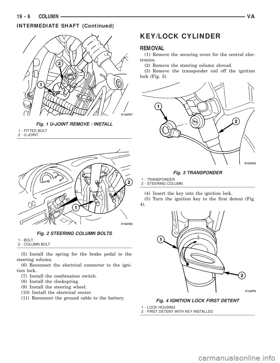
(Fig. 1).
(12) Remove the bolts in the steering column
bracket (Fig. 2).
(13) Remove the steering shaft with the universal
joint off the steering gear drive shaft (Fig. 1).
(14) Pull the steering shaft out of the rubber grom-
met in the cab floor.
INSTALLATION
(1) Install the steering shaft through the rubber
grommet in the cab floor.Ensure that the rubber
grommet is properly seated.
(2) Install the steering shaft with the universal
joint onto the steering gear shaft (Fig. 1).
(3) Install the bolts in the steering column bracket
(Fig. 2). Tighten to 24 N´m (18 ft. lbs.).
(4) Install the universal joint on the steering gear
shaft (Fig. 1). Tighten to 24 N´m (18 ft. lbs.).
VACOLUMN 19 - 5
Page 866 of 1232
(5) Install the spring for the brake pedal to the
steering column.
(6) Reconnect the electrical connector to the igni-
tion lock.
(7) Install the combination switch.
(8) Install the clockspring.
(9) Install the steering wheel.
(10) Install the electrical center.
(11) Reconnect the ground cable to the battery.
KEY/LOCK CYLINDER
REMOVAL
(1) Remove the securing cover for the central elec-
tronics.
(2) Remove the steering column shroud.
(3) Remove the transponder coil off the ignition
lock (Fig. 3).
(4) Insert the key into the ignition lock.
(5) Turn the ignition key to the first detent (Fig.
4).
Fig. 1 U-JOINT REMOVE / INSTALL
1 - FITTED BOLT
2 - U-JOINT
Fig. 2 STEERING COLUMN BOLTS
1 - BOLT
2 - COLUMN BOLT
Fig. 3 TRANSPONDER
1 - TRANSPONDER
2 - STEERING COLUMN
Fig. 4 IGNITION LOCK FIRST DETENT
1 - LOCK HOUSING
2 - FIRST DETENT WITH KEY INSTALLED
19 - 6 COLUMNVA
INTERMEDIATE SHAFT (Continued)
Page 867 of 1232
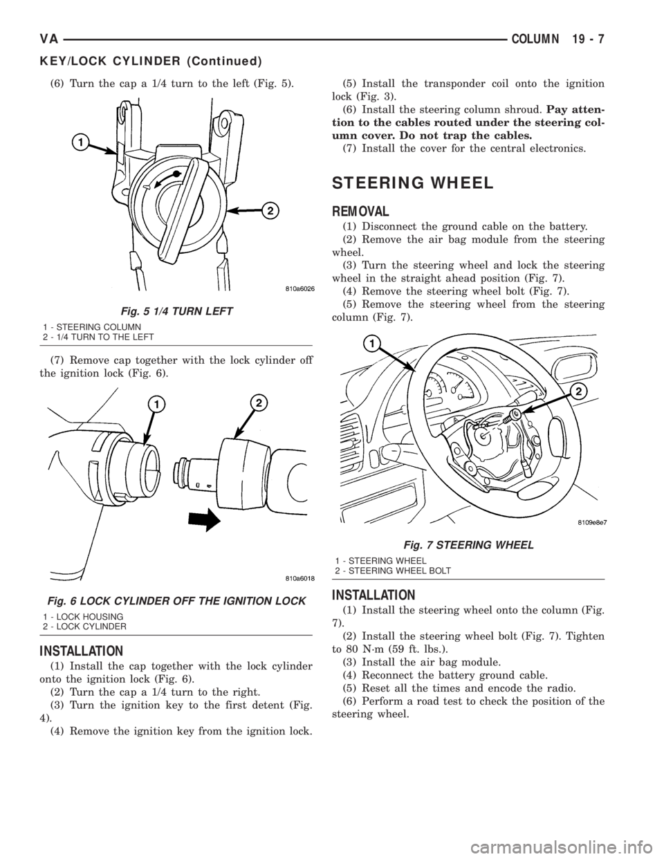
(6) Turn the cap a 1/4 turn to the left (Fig. 5).
(7) Remove cap together with the lock cylinder off
the ignition lock (Fig. 6).
INSTALLATION
(1) Install the cap together with the lock cylinder
onto the ignition lock (Fig. 6).
(2) Turn the cap a 1/4 turn to the right.
(3) Turn the ignition key to the first detent (Fig.
4).
(4) Remove the ignition key from the ignition lock.(5) Install the transponder coil onto the ignition
lock (Fig. 3).
(6) Install the steering column shroud.Pay atten-
tion to the cables routed under the steering col-
umn cover. Do not trap the cables.
(7) Install the cover for the central electronics.
STEERING WHEEL
REMOVAL
(1) Disconnect the ground cable on the battery.
(2) Remove the air bag module from the steering
wheel.
(3) Turn the steering wheel and lock the steering
wheel in the straight ahead position (Fig. 7).
(4) Remove the steering wheel bolt (Fig. 7).
(5) Remove the steering wheel from the steering
column (Fig. 7).
INSTALLATION
(1) Install the steering wheel onto the column (Fig.
7).
(2) Install the steering wheel bolt (Fig. 7). Tighten
to 80 N´m (59 ft. lbs.).
(3) Install the air bag module.
(4) Reconnect the battery ground cable.
(5) Reset all the times and encode the radio.
(6) Perform a road test to check the position of the
steering wheel.
Fig. 5 1/4 TURN LEFT
1 - STEERING COLUMN
2 - 1/4 TURN TO THE LEFT
Fig. 6 LOCK CYLINDER OFF THE IGNITION LOCK
1 - LOCK HOUSING
2 - LOCK CYLINDER
Fig. 7 STEERING WHEEL
1 - STEERING WHEEL
2 - STEERING WHEEL BOLT
VACOLUMN 19 - 7
KEY/LOCK CYLINDER (Continued)