2005 MERCEDES-BENZ SPRINTER clock
[x] Cancel search: clockPage 191 of 1232
OPERATION
The multi-function indicator has several display
capabilities including odometer, trip odometer, clock,
engine oil level data, gear selector indicator
(PRNDL), certain diagnostic information and, on
vehicles so equipped, an optional Active Service SYS-
Tem (ASSYST) engine oil maintenance indicator and
an optional outside ambient temperature indicator.
The multi-function indicator is completely controlled
by the instrument cluster logic circuit, and that logic
will allow this indication to be viewed whenever the
multi-function indicator Liquid Crystal Display
(LCD) is activated. Therefore, the indicator remains
functional regardless of the ignition switch position.
With the ignition switch in the Off or Accessory posi-
tions and the key removed from the ignition lock cyl-
inder, the display is activated when the park lamps
are turned On or, for about thirty seconds after any
one of the multi-function indicator switch push but-
tons is depressed. Otherwise, the display unit is
active for about thirty seconds after the key is
inserted into the ignition lock cylinder, and inactive
about thirty seconds after the key is removed from
the ignition lock cylinder.
The multi-function indicator ªmiº (miles) or
ªkmº(kilometers) switch push button is used to con-
trol the odometer/trip odometer display modes. The
multi-function indicator clock switch push button is
used to control the clock/outside temperature display
modes. The multi-function indicator ª+º (plus) and
ª2º (minus) switch push buttons are used to adjust
the cluster general illumination dimming level, the
clock, and other cluster settings. See the owner's
manual in the vehicle glove box for more information
on the features, use, operation and setting proce-
dures for the various standard and optional multi-
function indicator displays.
Proper testing of the multi-function indicator LCD
unit, the CAN data bus and the electronic data bus
message inputs to the instrument cluster that control
some of the multi-function indicator functions
requires the use of a DRBIIItscan tool. Refer to the
appropriate diagnostic information. Additional details
for the odometer/trip odometer, the clock, the gear
selector indicator, the ambient temperature indicator
and the ASSYST warning and reminder functions of
the multi-function indicator may be found elsewhere
in this service information.
ODOMETER
DESCRIPTION
An odometer and trip odometer are standard
equipment in all instrument clusters. The odometer
and trip odometer values are displayed on the leftside of the multi-function indicator Liquid Crystal
Display (LCD). The LCD is soldered onto the cluster
electronic circuit board and is visible through a win-
dow with a clear lens located near the lower edge of
the instrument cluster, directly below the speedome-
ter. However, the odometer and trip odometer infor-
mation are not displayed simultaneously. The ªmiº
(miles) or ªkmº (kilometers) switch on the instrument
cluster circuit board toggles the display between
odometer and trip odometer modes by depressing the
switch push button that extends through the lower
edge of the cluster lens, directly below the multi-
function indicator LCD.
The odometer and trip odometer information is
stored in the instrument cluster memory. This infor-
mation can be increased when the proper inputs are
provided to the instrument cluster, but the informa-
tion cannot be decreased. The odometer can display
values up to 999,999 kilometers (999,999 miles). The
odometer latches at these values, and will not roll
over to zero. The trip odometer can display values up
to 999.9 kilometers (999.9 miles) before it rolls over
to zero. The odometer display does not have a deci-
mal point and will not show values less than a full
unit (kilometer or mile), while the trip odometer dis-
play does have a decimal point and will show tenths
of a unit (kilometer or mile). The unit of measure
(kilometers or miles) for the odometer and trip odom-
eter display is imprinted on the cluster overlay below
the left end of the LCD. The unit of measure for the
instrument cluster odometer/trip odometer is selected
at the time that it is manufactured, and cannot be
changed.
The indications of the odometer/trip odometer are
not visible when the LCD is not illuminated. When
illuminated the indications appear as dark charac-
ters silhouetted against an amber field. When the
exterior lighting is turned Off, the display is illumi-
nated at maximum brightness. When the exterior
lighting is turned On the display illumination level
can be adjusted in concert with the cluster general
illumination lighting using the plus and minus multi-
function indicator push buttons. The odometer has a
ªRental Carº mode, which will activate the multi-
function indicator LCD and illuminate the odometer
information for about thirty seconds after one of the
multi-function indicator push buttons is momentarily
depressed, or after the key is inserted into the igni-
tion switch lock cylinder with the ignition switch in
the Off position.
The odometer/trip odometer and the miles/kilome-
ters switch, and the miles/kilometers switch push
button are serviced as a unit with the instrument
cluster.
VAINSTRUMENT CLUSTER 8J - 21
MULTI-FUNCTION INDICATOR (Continued)
Page 204 of 1232
INSTALLATION
(1) Install the backup lamp bulb into the tail lamp
socket plate (Fig. 3).
(2) Align the socket plate with the mounting hole
in the inner rear pillar.
(3) Using hand pressure, push the socket plate
gently and evenly into the inner rear pillar mounting
hole until both latch tabs are fully engaged (Fig. 2).
(4) If the vehicle is so equipped, reinstall the trim
onto the inside of the right or left rear corner pillar.
(5) Reconnect the battery negative cable.
BRAKE LAMP SWITCH
REMOVAL
(1) Disconnect and isolate the battery negative
cable.
(2) Locate the brake lamp switch on the pedal
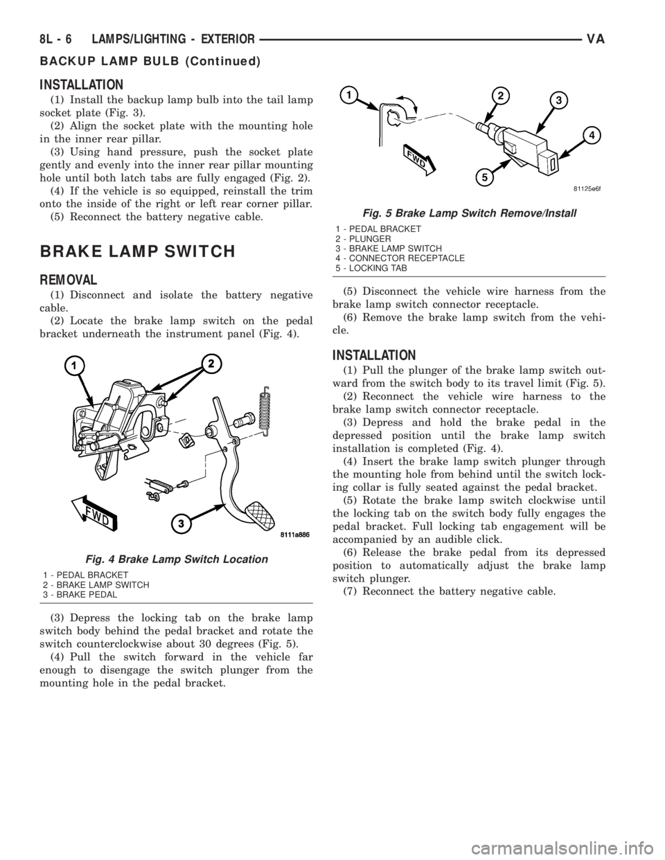
bracket underneath the instrument panel (Fig. 4).
(3) Depress the locking tab on the brake lamp
switch body behind the pedal bracket and rotate the
switch counterclockwise about 30 degrees (Fig. 5).
(4) Pull the switch forward in the vehicle far
enough to disengage the switch plunger from the
mounting hole in the pedal bracket.(5) Disconnect the vehicle wire harness from the
brake lamp switch connector receptacle.
(6) Remove the brake lamp switch from the vehi-
cle.
INSTALLATION
(1) Pull the plunger of the brake lamp switch out-
ward from the switch body to its travel limit (Fig. 5).
(2) Reconnect the vehicle wire harness to the
brake lamp switch connector receptacle.
(3) Depress and hold the brake pedal in the
depressed position until the brake lamp switch
installation is completed (Fig. 4).
(4) Insert the brake lamp switch plunger through
the mounting hole from behind until the switch lock-
ing collar is fully seated against the pedal bracket.
(5) Rotate the brake lamp switch clockwise until
the locking tab on the switch body fully engages the
pedal bracket. Full locking tab engagement will be
accompanied by an audible click.
(6) Release the brake pedal from its depressed
position to automatically adjust the brake lamp
switch plunger.
(7) Reconnect the battery negative cable.
Fig. 4 Brake Lamp Switch Location
1 - PEDAL BRACKET
2 - BRAKE LAMP SWITCH
3 - BRAKE PEDAL
Fig. 5 Brake Lamp Switch Remove/Install
1 - PEDAL BRACKET
2 - PLUNGER
3 - BRAKE LAMP SWITCH
4 - CONNECTOR RECEPTACLE
5 - LOCKING TAB
8L - 6 LAMPS/LIGHTING - EXTERIORVA
BACKUP LAMP BULB (Continued)
Page 205 of 1232
BRAKE/PARK LAMP BULB
REMOVAL
(1) Disconnect and isolate the battery negative
cable.
(2) If the vehicle is so equipped, remove the trim
from the inside of the right or left rear corner pillar.
(3) From inside the vehicle, use hand pressure to
push the two latch tabs toward the center of the tail
lamp unit socket plate and pull the socket plate
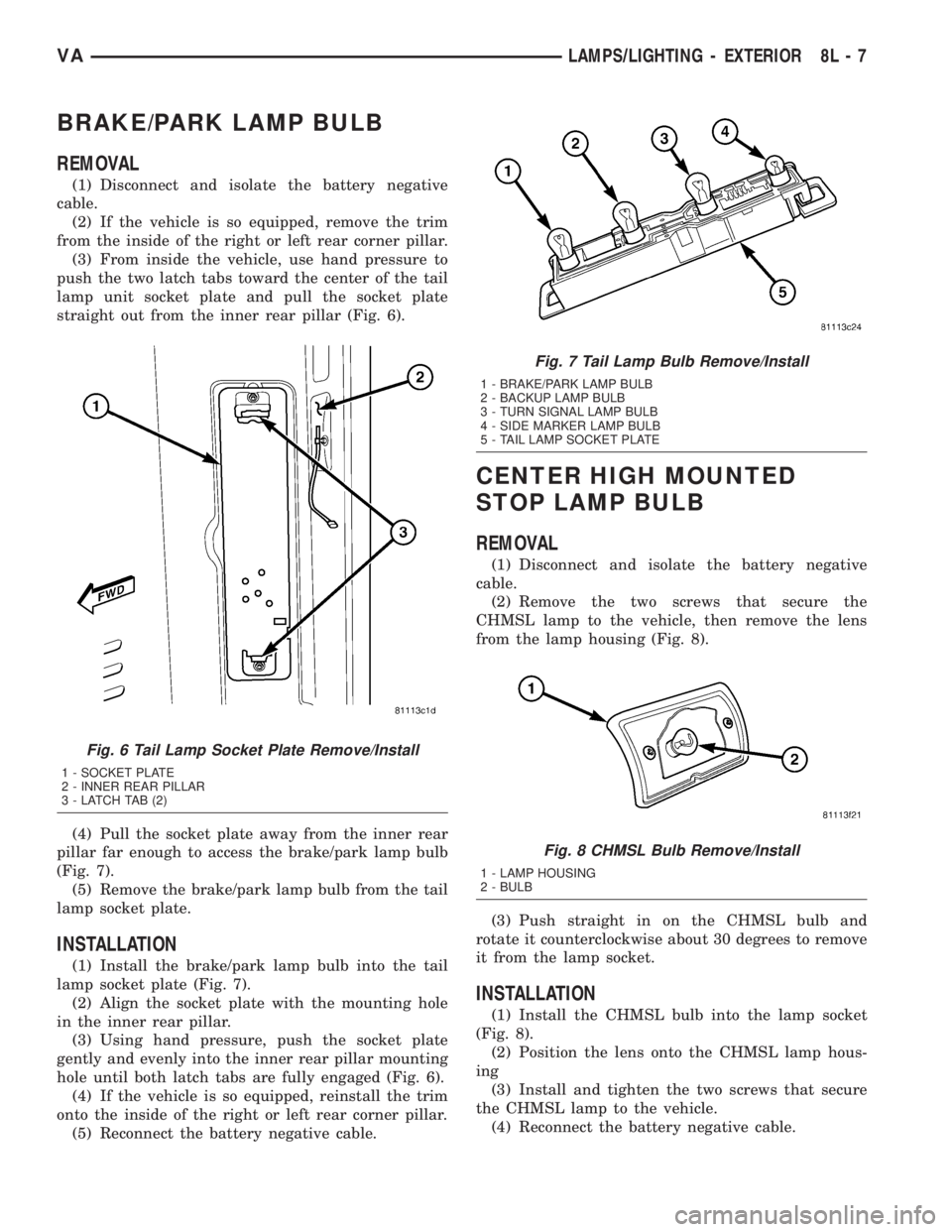
straight out from the inner rear pillar (Fig. 6).
(4) Pull the socket plate away from the inner rear
pillar far enough to access the brake/park lamp bulb
(Fig. 7).
(5) Remove the brake/park lamp bulb from the tail
lamp socket plate.
INSTALLATION
(1) Install the brake/park lamp bulb into the tail
lamp socket plate (Fig. 7).
(2) Align the socket plate with the mounting hole
in the inner rear pillar.
(3) Using hand pressure, push the socket plate
gently and evenly into the inner rear pillar mounting
hole until both latch tabs are fully engaged (Fig. 6).
(4) If the vehicle is so equipped, reinstall the trim
onto the inside of the right or left rear corner pillar.
(5) Reconnect the battery negative cable.
CENTER HIGH MOUNTED
STOP LAMP BULB
REMOVAL
(1) Disconnect and isolate the battery negative
cable.
(2) Remove the two screws that secure the
CHMSL lamp to the vehicle, then remove the lens
from the lamp housing (Fig. 8).
(3) Push straight in on the CHMSL bulb and
rotate it counterclockwise about 30 degrees to remove
it from the lamp socket.
INSTALLATION
(1) Install the CHMSL bulb into the lamp socket
(Fig. 8).
(2) Position the lens onto the CHMSL lamp hous-
ing
(3) Install and tighten the two screws that secure
the CHMSL lamp to the vehicle.
(4) Reconnect the battery negative cable.
Fig. 6 Tail Lamp Socket Plate Remove/Install
1 - SOCKET PLATE
2 - INNER REAR PILLAR
3 - LATCH TAB (2)
Fig. 7 Tail Lamp Bulb Remove/Install
1 - BRAKE/PARK LAMP BULB
2 - BACKUP LAMP BULB
3 - TURN SIGNAL LAMP BULB
4 - SIDE MARKER LAMP BULB
5 - TAIL LAMP SOCKET PLATE
Fig. 8 CHMSL Bulb Remove/Install
1 - LAMP HOUSING
2 - BULB
VALAMPS/LIGHTING - EXTERIOR 8L - 7
Page 206 of 1232
CENTER HIGH MOUNTED
STOP LAMP UN
REMOVAL
(1) Disconnect and isolate the battery negative
cable.
(2) Remove the two screws that secure the
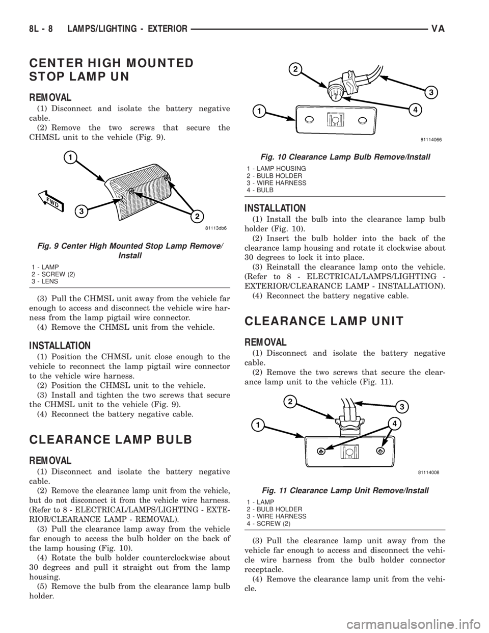
CHMSL unit to the vehicle (Fig. 9).
(3) Pull the CHMSL unit away from the vehicle far
enough to access and disconnect the vehicle wire har-
ness from the lamp pigtail wire connector.
(4) Remove the CHMSL unit from the vehicle.
INSTALLATION
(1) Position the CHMSL unit close enough to the
vehicle to reconnect the lamp pigtail wire connector
to the vehicle wire harness.
(2) Position the CHMSL unit to the vehicle.
(3) Install and tighten the two screws that secure
the CHMSL unit to the vehicle (Fig. 9).
(4) Reconnect the battery negative cable.
CLEARANCE LAMP BULB
REMOVAL
(1) Disconnect and isolate the battery negative
cable.
(2)
Remove the clearance lamp unit from the vehicle,
but do not disconnect it from the vehicle wire harness.
(Refer to 8 - ELECTRICAL/LAMPS/LIGHTING - EXTE-
RIOR/CLEARANCE LAMP - REMOVAL).
(3) Pull the clearance lamp away from the vehicle
far enough to access the bulb holder on the back of
the lamp housing (Fig. 10).
(4) Rotate the bulb holder counterclockwise about
30 degrees and pull it straight out from the lamp
housing.
(5) Remove the bulb from the clearance lamp bulb
holder.
INSTALLATION
(1) Install the bulb into the clearance lamp bulb
holder (Fig. 10).
(2) Insert the bulb holder into the back of the
clearance lamp housing and rotate it clockwise about
30 degrees to lock it into place.
(3) Reinstall the clearance lamp onto the vehicle.
(Refer to 8 - ELECTRICAL/LAMPS/LIGHTING -
EXTERIOR/CLEARANCE LAMP - INSTALLATION).
(4) Reconnect the battery negative cable.
CLEARANCE LAMP UNIT
REMOVAL
(1) Disconnect and isolate the battery negative
cable.
(2) Remove the two screws that secure the clear-
ance lamp unit to the vehicle (Fig. 11).
(3) Pull the clearance lamp unit away from the
vehicle far enough to access and disconnect the vehi-
cle wire harness from the bulb holder connector
receptacle.
(4) Remove the clearance lamp unit from the vehi-
cle.
Fig. 9 Center High Mounted Stop Lamp Remove/
Install
1 - LAMP
2 - SCREW (2)
3 - LENS
Fig. 10 Clearance Lamp Bulb Remove/Install
1 - LAMP HOUSING
2 - BULB HOLDER
3 - WIRE HARNESS
4 - BULB
Fig. 11 Clearance Lamp Unit Remove/Install
1 - LAMP
2 - BULB HOLDER
3 - WIRE HARNESS
4 - SCREW (2)
8L - 8 LAMPS/LIGHTING - EXTERIORVA
Page 213 of 1232
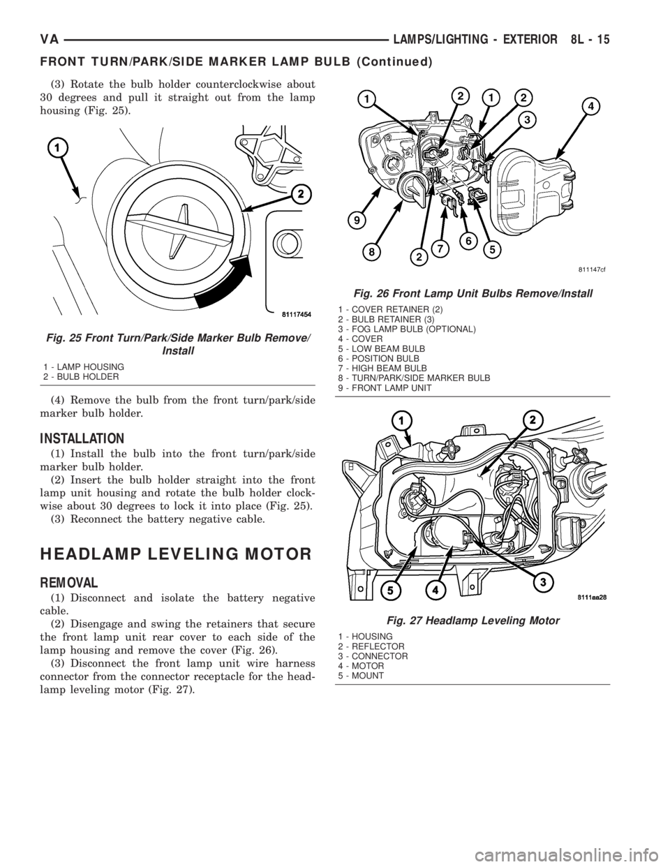
(3) Rotate the bulb holder counterclockwise about
30 degrees and pull it straight out from the lamp
housing (Fig. 25).
(4) Remove the bulb from the front turn/park/side
marker bulb holder.
INSTALLATION
(1) Install the bulb into the front turn/park/side
marker bulb holder.
(2) Insert the bulb holder straight into the front
lamp unit housing and rotate the bulb holder clock-
wise about 30 degrees to lock it into place (Fig. 25).
(3) Reconnect the battery negative cable.
HEADLAMP LEVELING MOTOR
REMOVAL
(1) Disconnect and isolate the battery negative
cable.
(2) Disengage and swing the retainers that secure
the front lamp unit rear cover to each side of the
lamp housing and remove the cover (Fig. 26).
(3) Disconnect the front lamp unit wire harness
connector from the connector receptacle for the head-
lamp leveling motor (Fig. 27).
Fig. 25 Front Turn/Park/Side Marker Bulb Remove/
Install
1 - LAMP HOUSING
2 - BULB HOLDER
Fig. 26 Front Lamp Unit Bulbs Remove/Install
1 - COVER RETAINER (2)
2 - BULB RETAINER (3)
3 - FOG LAMP BULB (OPTIONAL)
4 - COVER
5 - LOW BEAM BULB
6 - POSITION BULB
7 - HIGH BEAM BULB
8 - TURN/PARK/SIDE MARKER BULB
9 - FRONT LAMP UNIT
Fig. 27 Headlamp Leveling Motor
1 - HOUSING
2 - REFLECTOR
3 - CONNECTOR
4 - MOTOR
5 - MOUNT
VALAMPS/LIGHTING - EXTERIOR 8L - 15
FRONT TURN/PARK/SIDE MARKER LAMP BULB (Continued)
Page 214 of 1232
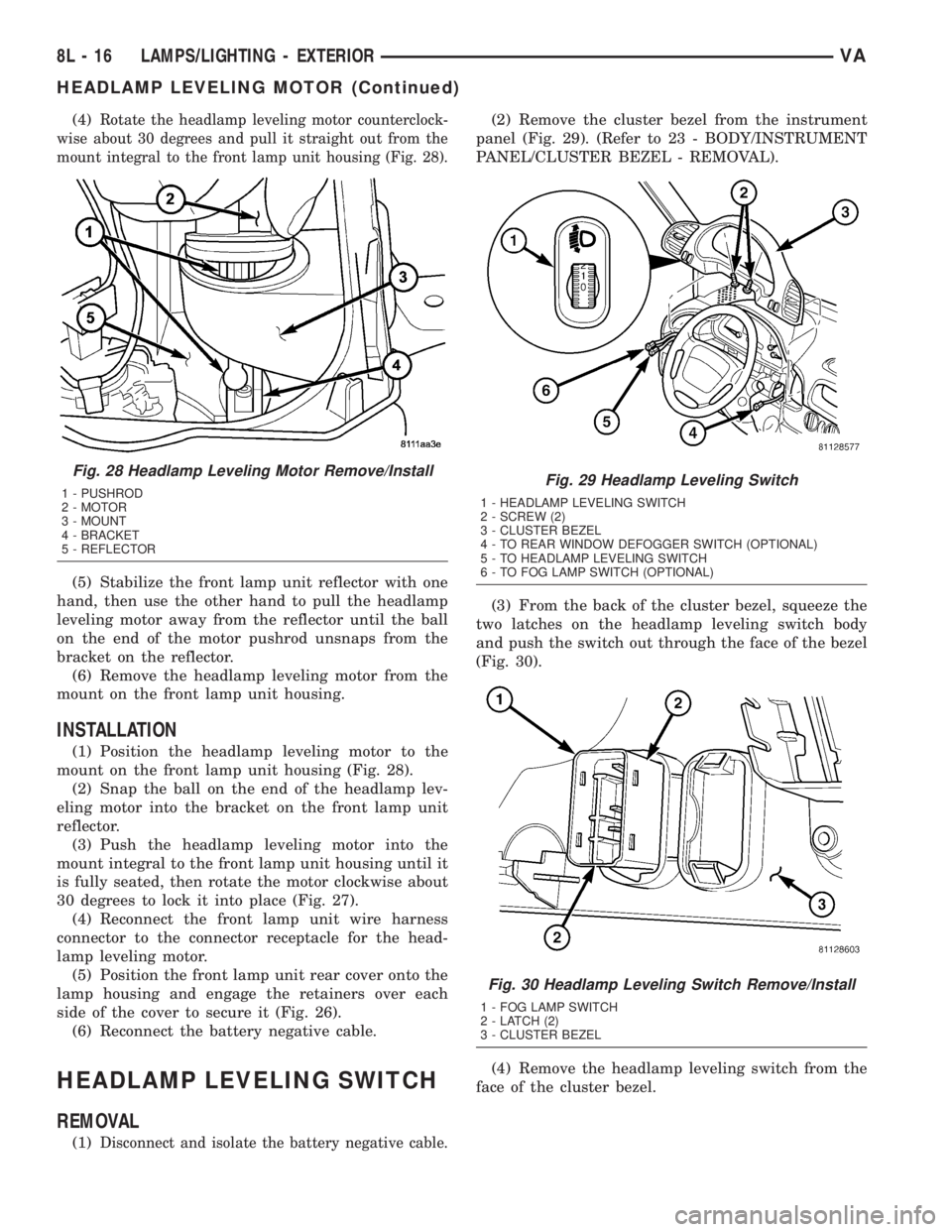
(4)Rotate the headlamp leveling motor counterclock-
wise about 30 degrees and pull it straight out from the
mount integral to the front lamp unit housing (Fig. 28).
(5) Stabilize the front lamp unit reflector with one
hand, then use the other hand to pull the headlamp
leveling motor away from the reflector until the ball
on the end of the motor pushrod unsnaps from the
bracket on the reflector.
(6) Remove the headlamp leveling motor from the
mount on the front lamp unit housing.
INSTALLATION
(1) Position the headlamp leveling motor to the
mount on the front lamp unit housing (Fig. 28).
(2) Snap the ball on the end of the headlamp lev-
eling motor into the bracket on the front lamp unit
reflector.
(3) Push the headlamp leveling motor into the
mount integral to the front lamp unit housing until it
is fully seated, then rotate the motor clockwise about
30 degrees to lock it into place (Fig. 27).
(4) Reconnect the front lamp unit wire harness
connector to the connector receptacle for the head-
lamp leveling motor.
(5) Position the front lamp unit rear cover onto the
lamp housing and engage the retainers over each
side of the cover to secure it (Fig. 26).
(6) Reconnect the battery negative cable.
HEADLAMP LEVELING SWITCH
REMOVAL
(1)Disconnect and isolate the battery negative cable.
(2) Remove the cluster bezel from the instrument
panel (Fig. 29). (Refer to 23 - BODY/INSTRUMENT
PANEL/CLUSTER BEZEL - REMOVAL).
(3) From the back of the cluster bezel, squeeze the
two latches on the headlamp leveling switch body
and push the switch out through the face of the bezel
(Fig. 30).
(4) Remove the headlamp leveling switch from the
face of the cluster bezel.
Fig. 28 Headlamp Leveling Motor Remove/Install
1 - PUSHROD
2 - MOTOR
3 - MOUNT
4 - BRACKET
5 - REFLECTORFig. 29 Headlamp Leveling Switch
1 - HEADLAMP LEVELING SWITCH
2 - SCREW (2)
3 - CLUSTER BEZEL
4 - TO REAR WINDOW DEFOGGER SWITCH (OPTIONAL)
5 - TO HEADLAMP LEVELING SWITCH
6 - TO FOG LAMP SWITCH (OPTIONAL)
Fig. 30 Headlamp Leveling Switch Remove/Install
1 - FOG LAMP SWITCH
2 - LATCH (2)
3 - CLUSTER BEZEL
8L - 16 LAMPS/LIGHTING - EXTERIORVA
HEADLAMP LEVELING MOTOR (Continued)
Page 217 of 1232
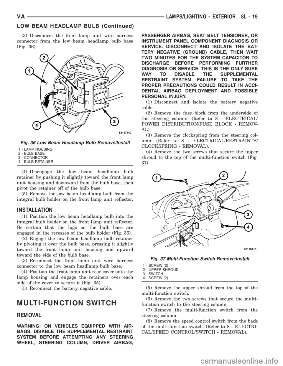
(3) Disconnect the front lamp unit wire harness
connector from the low beam headlamp bulb base
(Fig. 36).
(4) Disengage the low beam headlamp bulb
retainer by pushing it slightly toward the front lamp
unit housing and downward from the bulb base, then
pivot the retainer off of the bulb base.
(5) Remove the low beam headlamp bulb from the
integral bulb holder on the front lamp unit reflector.
INSTALLATION
(1) Position the low beam headlamp bulb into the
integral bulb holder on the front lamp unit reflector.
Be certain that the lugs on the bulb base are
engaged in the recesses of the bulb holder (Fig. 36).
(2) Engage the low beam headlamp bulb retainer
by pivoting it over the bulb base, pressing it slightly
toward the front lamp unit housing and upward
toward the side of the bulb base.
(3) Reconnect the front lamp unit wire harness
connector to the low beam headlamp bulb base.
(4) Position the front lamp unit rear cover onto the
lamp housing and engage the retainers over each
side of the cover to secure it (Fig. 35).
(5) Reconnect the battery negative cable.
MULTI-FUNCTION SWITCH
REMOVAL
WARNING: ON VEHICLES EQUIPPED WITH AIR-
BAGS, DISABLE THE SUPPLEMENTAL RESTRAINT
SYSTEM BEFORE ATTEMPTING ANY STEERING
WHEEL, STEERING COLUMN, DRIVER AIRBAG,PASSENGER AIRBAG, SEAT BELT TENSIONER, OR
INSTRUMENT PANEL COMPONENT DIAGNOSIS OR
SERVICE. DISCONNECT AND ISOLATE THE BAT-
TERY NEGATIVE (GROUND) CABLE, THEN WAIT
TWO MINUTES FOR THE SYSTEM CAPACITOR TO
DISCHARGE BEFORE PERFORMING FURTHER
DIAGNOSIS OR SERVICE. THIS IS THE ONLY SURE
WAY TO DISABLE THE SUPPLEMENTAL
RESTRAINT SYSTEM. FAILURE TO TAKE THE
PROPER PRECAUTIONS COULD RESULT IN ACCI-
DENTAL AIRBAG DEPLOYMENT AND POSSIBLE
PERSONAL INJURY.
(1) Disconnect and isolate the battery negative
cable.
(2) Remove the fuse block from the underside of
the steering column. (Refer to 8 - ELECTRICAL/
POWER DISTRIBUTION/FUSE BLOCK - REMOV-
AL).
(3) Remove the clockspring from the steering col-
umn. (Refer to 8 - ELECTRICAL/RESTRAINTS/
CLOCKSPRING - REMOVAL).
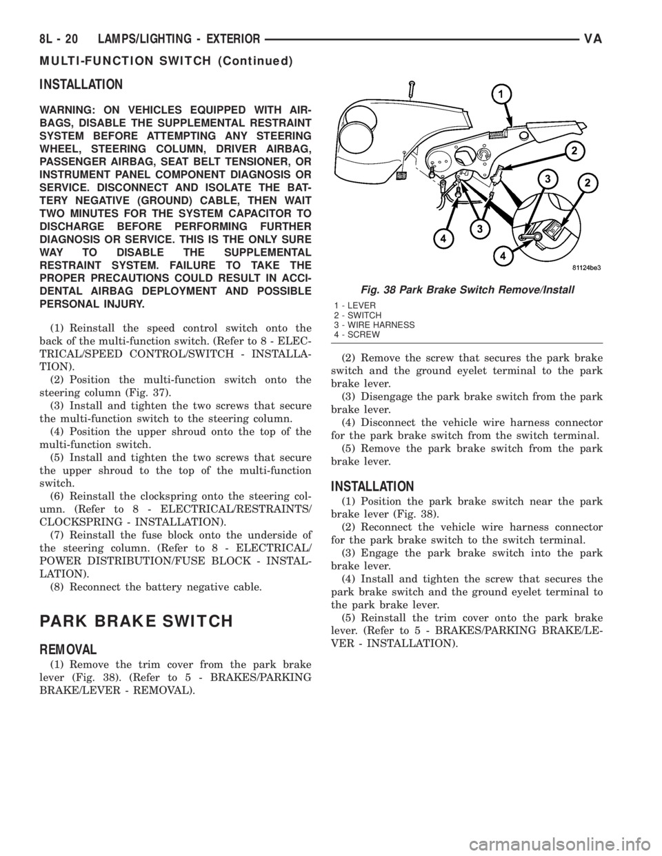
(4) Remove the two screws that secure the upper
shroud to the top of the multi-function switch (Fig.
37).
(5) Remove the upper shroud from the top of the
multi-function switch.
(6) Remove the two screws that secure the multi-
function switch to the steering column.
(7) Remove the multi-function switch from the
steering column.
(8) Remove the speed control switch from the back
of the multi-function switch. (Refer to 8 - ELECTRI-
CAL/SPEED CONTROL/SWITCH - REMOVAL).
Fig. 36 Low Beam Headlamp Bulb Remove/Install
1 - LAMP HOUSING
2 - BULB BASE
3 - CONNECTOR
4 - BULB RETAINER
Fig. 37 Multi-Function Switch Remove/Install
1 - SCREW (2)
2 - UPPER SHROUD
3 - SWITCH
4 - SCREW (2)
VALAMPS/LIGHTING - EXTERIOR 8L - 19
LOW BEAM HEADLAMP BULB (Continued)
Page 218 of 1232
INSTALLATION
WARNING: ON VEHICLES EQUIPPED WITH AIR-
BAGS, DISABLE THE SUPPLEMENTAL RESTRAINT
SYSTEM BEFORE ATTEMPTING ANY STEERING
WHEEL, STEERING COLUMN, DRIVER AIRBAG,
PASSENGER AIRBAG, SEAT BELT TENSIONER, OR
INSTRUMENT PANEL COMPONENT DIAGNOSIS OR
SERVICE. DISCONNECT AND ISOLATE THE BAT-
TERY NEGATIVE (GROUND) CABLE, THEN WAIT
TWO MINUTES FOR THE SYSTEM CAPACITOR TO
DISCHARGE BEFORE PERFORMING FURTHER
DIAGNOSIS OR SERVICE. THIS IS THE ONLY SURE
WAY TO DISABLE THE SUPPLEMENTAL
RESTRAINT SYSTEM. FAILURE TO TAKE THE
PROPER PRECAUTIONS COULD RESULT IN ACCI-
DENTAL AIRBAG DEPLOYMENT AND POSSIBLE
PERSONAL INJURY.
(1) Reinstall the speed control switch onto the
back of the multi-function switch. (Refer to 8 - ELEC-
TRICAL/SPEED CONTROL/SWITCH - INSTALLA-
TION).
(2) Position the multi-function switch onto the
steering column (Fig. 37).
(3) Install and tighten the two screws that secure
the multi-function switch to the steering column.
(4) Position the upper shroud onto the top of the
multi-function switch.
(5) Install and tighten the two screws that secure
the upper shroud to the top of the multi-function
switch.
(6) Reinstall the clockspring onto the steering col-
umn. (Refer to 8 - ELECTRICAL/RESTRAINTS/
CLOCKSPRING - INSTALLATION).
(7) Reinstall the fuse block onto the underside of
the steering column. (Refer to 8 - ELECTRICAL/
POWER DISTRIBUTION/FUSE BLOCK - INSTAL-
LATION).
(8) Reconnect the battery negative cable.
PARK BRAKE SWITCH
REMOVAL
(1) Remove the trim cover from the park brake
lever (Fig. 38). (Refer to 5 - BRAKES/PARKING
BRAKE/LEVER - REMOVAL).(2) Remove the screw that secures the park brake
switch and the ground eyelet terminal to the park
brake lever.
(3) Disengage the park brake switch from the park
brake lever.
(4) Disconnect the vehicle wire harness connector
for the park brake switch from the switch terminal.
(5) Remove the park brake switch from the park
brake lever.
INSTALLATION
(1) Position the park brake switch near the park
brake lever (Fig. 38).
(2) Reconnect the vehicle wire harness connector
for the park brake switch to the switch terminal.
(3) Engage the park brake switch into the park
brake lever.
(4) Install and tighten the screw that secures the
park brake switch and the ground eyelet terminal to
the park brake lever.
(5) Reinstall the trim cover onto the park brake
lever. (Refer to 5 - BRAKES/PARKING BRAKE/LE-
VER - INSTALLATION).
Fig. 38 Park Brake Switch Remove/Install
1 - LEVER
2 - SWITCH
3 - WIRE HARNESS
4 - SCREW
8L - 20 LAMPS/LIGHTING - EXTERIORVA
MULTI-FUNCTION SWITCH (Continued)